2AWSWMS-ZNUWZunion UV Wireless Pad
MOBISTAR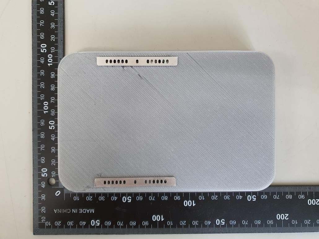
Click to zoom
Application Details
- Equipment Class
- DCD - Part 15 Low Power Transmitter Below 1705 kHz
- Date of Grant
- Jul 12, 2020
- Application Purpose
- Original Equipment
- Date of Application
- Jul 12, 2020
- Equipment Note
- Zunion UV Wireless Pad
- Frequency Range
- 0.11000000 - 0.20500000
- Company
- MOBISTAR
- Country
- South Korea
Documents & Files
Document Text
Text extracted from the exhibit documents filed with the FCC. Open a document above to read the original.
Users Manual
Copyright ⓒ 2020. Lab-T, Inc. User Manual User manual MS-ZNUW MOBISTAR 3F 303-16, 397, Seokcheon-ro, Bucheon-si Gyeonggi-do 14449, South Korea Please read this manual before using the device to ensure safe and proper use. • Appearances and specifications are subject to change without prior notice. • Wireless charging covers and chargers are sold separately. Using the wireless charger Charging your mobile device Wireless charging 1. Connect a charger to the wireless charger. When properly connected, the product's status indicator lights up UV-C and a blue light illuminates for 30 seconds. Use only approved chargers (5 V/2 A, 5.3 V/2 A, and 9 V/1.67 A). Unauthorised chargers may cause damage or the wireless charger may malfunction. 2. Place a supported mobile device in the centre of the charging surface. Check the charging icon displayed on the mobile device’s screen for the charging status. The color of the status indicator tells you the status of the product. Red: Wireless charging in progress Green: Wireless charging completed To charge a mobile device that does not have a built-in wireless charging coil, attach a wireless charging cover to the mobile device. Then, place the mobile device on the wireless charger. • If the status indicator does not work properly or is recognized incorrectly, disconnect the charger and connect it again. • Depending on the mobile device (or wireless charging cover), the status indicator may appear differently. • To charge a mobile device that does not have a built-in wireless charging coil, place it on the product with the charging cover attached to the mobile device. • Do not place the wireless charging cover solely on the wireless charger. Doing so may overheat the wireless charger and cause a fire. It may also result in serious burn or device malfunction. 3. When the mobile device is fully charged, remove it from the wireless charger. Do not place foreign materials, such as metal objects, magnets, and magnetic stripe cards, between the mobile device and the wireless charger. The mobile device may not charge properly or may be damaged due to overheating. • You may need to purchase a charger separately depending on the wireless charger you bought. • When the mobile device is not placed on the charging surface properly, or depending on the location of the mobile device’s wireless charging coil, your mobile device may not charge properly. • Depending on the location of the mobile device’s wireless charging coil, your mobile device may not charge properly. • Wireless charging may not work properly if you have attached a thick case to your mobile device. If your case is thick, remove it before placing your mobile device on the wireless charger. • If you use the wireless charger in areas with weak network signals, you may lose network reception. • If you connect a charger to the mobile device during wireless charging, the wireless charging feature will be unavailable. • The wireless charger is compatible with WPC certified devices. • To save energy, unplug the charger when not in use. The charger does not have a power switch, so you must unplug the charger from the electric socket when not in use to avoid wasting power. The charger should remain close to the electric socket and be easily accessible while charging. • The socket-outlet shall be installed near the equipment and shall be easily accessible. Fast wireless charging The wireless charger supports fast wireless charging. To begin fast wireless charging, place a mobile device that supports fast wireless charging on the wireless charger. Use only approved chargers that support fast charging (9 V/1.67 A). Activating or deactivating the fast wireless charging feature The fast wireless charging option will be added in your mobile device’s settings menu when you place it on the wireless charger for the first time. Place the mobile device on the wireless charger. On the Home screen of the mobile device, tap Apps → Settings → Accessories, and then tap the Fast wireless charging switch to activate or deactivate it. Deactivating this feature will switch the charging mode to normal wireless charging and result in slower charging times. Specification • Radio Frequency Range: 110 kHz ~ 205 kHz • Modulation: ASK • Input voltage: DC 5.0 V, 2.0 A or DC 9.0 V 1.67 A • Charging distance: ≤ 10 mm • Size: (165 * 105 * 15) mm • Weight: Approx. 150g Compliance Statement This device complies with part 15 of the FCC Rules. Operation is subject to the following two conditions : (1) This device may not cause harmful interference, and (2) This device must accept any interference received, including interference that may cause undesired operation. A minimum separation distance of 20 cm must be maintained between the antenna and the person for this appliance to satisfy the RF exposure requirements CAUTION: Changes or modifications not expressly approved by the party responsible for compliance could void the user’s authority to operate the equipment.
Cover Letter(s)
SCS-F19: Confidentiality Request Letter Page 1 of 3 Rev 6.0 775 Montague Expressway Milpitas, CA 95035 Tel: 408-526-1188 Fax: 408-526-1088 Email: [email protected] Confidentiality Request Letter Reason for Amendment (current / obsolete) Revision History Approved Date From To Initial Release (obsolete) 1.0 1.0 Nov-14-2006 Adding CFR 2.459 (obsolete) 1.0 2.0 August – 11 - 2008 Updated company template & Added text box (obsolete) 2.0 3.0 Jan-31-2012 Added IC confidentiality letter form (obsolete) 3.0 4.0 March-26-2015 Corrections to STC form. Added reference to KDB (obsolete) 4.0 5.0 Nov-19-2015 Updated company logo (current) 5.0 6.0 Jun-26-2019 SCS-F19: Confidentiality Request Letter Page 2 of 3 Rev 6.0 MOBISTAR 3F 303-16, 397, Seokcheon-ro, Bucheon-si, Gyeonggi-do 14449, South Korea Date : Jul, 02, 2020 To: Federal Communications Commission Authorization and Evaluation Division 7435 Oakland Mills Road Columbia, MD Subject: Permanent Confidentiality Request for FCC ID: 2AWSWMS-ZNUW Pursuant to sections 0.457 and 0.459 of CFR 47, we respectfully request permanent confidential treatment of the following Exhibits accompanying this application as: - Block Diagram - Schematics - Operational Description The above materials contain trade secrets and proprietary information not customarily released to the public. The public disclosure of these materials may be harmful to the applicant and provide unjustified benefits to its competitors. The applicant understands that disclosure of this application and all accompanying documentation will not be made before the date of the Grant for this application. Sincerely, (Signature) Hyun-Jong Chung / CEO +82-10-2999-9367 3F 303-16, 397, Seokcheon-ro, Bucheon-si, Gyeonggi-do 14449, South Korea SCS-F19: Confidentiality Request Letter Page 3 of 3 Rev 6.0 MOBISTAR 3F 303-16, 397, Seokcheon-ro, Bucheon-si, Gyeonggi-do 14449, South Korea Date : Jul, 02, 2020 To: Federal Communications Commission Office of Engineering and Technology Equipment Authorization Division 7345 Oakland Mills Road Columbia, Maryland 21046 Subject: Short Term Confidentiality Request for FCC ID: 2AWSWMS-ZNUW To Whom It May Concern: Pursuant to sections 0.457 and 0.459 of CFR 47, and to avoid premature release of sensitive information prior to marketing or release of the product to the public, the applicant requests the following documents contained in this certification application be temporarily withheld from public disclosure for an initial period of 45 or 180 days; or for a specified date of / / not to exceed 180 days from the Grant Date. See KDB 726920. - Internal Photos - External Photos - Test Setup photos - User manual The above materials contain trade secrets and proprietary information not customarily released to the public. The public disclosure of these materials may be harmful to the applicant and provide unjustified benefits to its competitors. Sincerely, (Signature) Hyun-Jong Chung / CEO +82-10-2999-9367 3F 303-16, 397, Seokcheon-ro, Bucheon-si, Gyeonggi-do 14449, South Korea
Cover Letter(s)
MOBISTAR 3F 303-16, 397, Seokcheon-ro, Bucheon-si, Gyeonggi-do 14449, South Korea Date : Jul, 02, 2020 Dear Sir/Madam, Re : Project and Product Certification Representative Authorization Letter We, MOBISTAR hereby authorize Bureau Veritas Consumer Product Services, Inc. to act as a Certification Body for certifying for the following project : - Product Type : Zunion UV Wireless Pad - Manufacturer : MOBISTAR - FCC ID : 2AWSWMS-ZNUW We, the undersigned, hereby authorize SangHoon, Yu of Lab-T, Inc. to act on our behalf in all manners relating to application for equipment authorization for FCCID: 2AWSWMS-ZNUW signing of all documents relating to these matters. Any and all acts carried out by SangHoon, Yu of Lab-T, Inc. on our behalf shall have the same affect as acts of our own. This authorization is valid until further written notice from MOBISTAR I, the undersigned, hereby certify that we are not subject to a denial of federal benefits, that includes FCC benefits, pursuant to Section 5301 of the Anti-Drug Abuse Act of 1988, 21 U.S.C. 853(a). This authorization is valid until further written notice from the applicant. Sincerely Yours, Hyun-Jong Chung CEO
Cover Letter(s)
MOBISTAR 3F 303-16, 397, Seokcheon-ro, Bucheon-si, Gyeonggi-do 14449, South Korea Date : Jul, 02, 2020 We, MOBISTAR, hereby declare that the following products are electrically identical. - Product Type : Zunion UV Wireless Pad - Model : 2AWSWMS-ZNUW - Variant Model : MS-ZNUW-P, MS-ZNUW-S, MS-ZNUW-C, MS-ZNUW-O, MS-ZNDC, MS-ZNDC-S, MS-ZNDC-P - Manufacturer : MOBISTAR - FCC ID : 2AWSWMS-ZNUW These models have the same circuit schematic, construction, PCB Layout and critical compone nts. The only difference is model number due to marketing or trading purposes. Sincerely, (Signature) Hyun-Jong Chung / CEO +82-10-2999-9367 3F 303-16, 397, Seokcheon-ro, Bucheon-si, Gyeonggi-do 14449, South Korea
External Photos
Page: 1 / 4 Copyright ⓒ 2020, Lab-T, Inc. External Photos Page: 2 / 4 Copyright ⓒ 2020, Lab-T, Inc. External Photos Front Rear Page: 3 / 4 Copyright ⓒ 2020, Lab-T, Inc. External Photos Top Bottom Page: 4 / 4 Copyright ⓒ 2020, Lab-T, Inc. External Photos Left Right
ID Label/Location Info
Copyright ⓒ 2020. Lab-T, Inc. FCC ID Label Information Copyright ⓒ 2020. Lab-T, Inc. FCC ID Label information Location Location
Internal Photos
Page: 1 / 5 Copyright ⓒ 2020. Lab-T, Inc. Internal Photos Page: 2 / 5 Copyright ⓒ 2020. Lab-T, Inc. Internal Photos Main Board_Front Main Board_Rear Page: 3 / 5 Copyright ⓒ 2020. Lab-T, Inc. Internal Photos Sub Board#1_Front Sub Board#1_Rear . Page: 4 / 5 Copyright ⓒ 2020. Lab-T, Inc. Internal Photos Sub Board#2_Front Sub Board#2_Rear Page: 5 / 5 Copyright ⓒ 2020. Lab-T, Inc. Internal Photos Coil Loop_Antenna
RF Exposure Info
REPORT No.:TRRFCC20-0008 1. Test Configuration 2. Limit For devices designed for typical desktop applications, such a wireless charging pads, RF exposure evaluation should be conducted assuming a user separation distance of 15 cm. E and H field strength measurements or numerical modeling may be used to demonstrate compliance. Measurements should be made from all sides and the top of the primary/client pair, with the 15 cm measured from the center of the probe(s) to the edge of the device. Emissions between 100 kHz to 300 kHz should be assessed versus the limits at 300 kHz in Table 1 of Section 1.1310: 614 V/m and 1.63 A/m. A KDB inquiry is required to determine the applicable exposure limits below 100 kHz. Frequency Range (MHz) Magnetic field Strength (A/m) Electric field strength (V/m) Averaging time (minutes) Power density (mW/cm2) Table 1—Limits for Maximum Permissible Exposure (MPE) 1,500 ~ 100,000 300 ~1,500 0.3 ~ 3.06141.63*1006 6*900/f2 RF EXPOSURE Note f = frequency in MHz * = Plane-wave equivalent power density 5 f/300 6 6 30 ~ 30027.50.0730.230 1.34 ~ 30824/f2.19/f*180/f230 61.00.16361.430 ~ 300 (A) Limits for Occupational/Controlled Exposure Per the guidance of KDB 680106, the E-field and H-field limits shown in the table above are extended down to 100kHz. 4.89/f1842/f3.0 ~ 30 (B) Limits for General Population/Uncontrolled Exposure *1001.636140.3 ~ 1.34 300 ~ 1,500f/150030 1,500 ~ 100,000130 30 Copyright ⓒ 2020. Lab-T, Inc. Page :1 / 6 REPORT No.:TRRFCC20-0008 3. Equipment Approval Considerations (1) Power transfer frequency is less than 1 MHz. (2) Output power from each primary coil is less than or equal to 15 watts. -it is that supports up to 15.03 W (9 V, 1.67 A) (4) Client device is placed directly in contact with the transmitter. -When the client device is placed directly in contact with transmitter, then charging is able to start. (5) Mobile exposure conditions only (portable exposure conditions are not covered by this exclusion). -Yes -Yes (refer to 3page) 4. Test Methods 4.1 Measurement procedure 4.2 Test diagram -The DUT(Device Under Test) includes two primary coils and Clients will be able to detect and allow coupling between individual pairs of coils. (6) The aggregate H-field strengths at 15 cm surrounding the device and 20 cm above the top surface from all simultaneous transmitting coils are demonstrated to be less than 50% of the MPE limit 1. The RF exposure test was performed at the turn table of anechoic chamber. 2. The edge of the charger(EUT) and center of the filed probe should be located at specified distance(15 cm, 20 cm). 3. Maximum value of E-field and H-field were measured for the six side each at the specified distance and recorded them on the following Test Result table. Six sides are [A]Front, [B]Left, [C]Rear, [D]Right, [E]Bottom and [F]Top. Please see below diagram. 4. The EUT was implemented by the dictates of KDB 680106D01v03 accordingly. -The power transfer frequency is set from 110 kHz to 205 kHz. Therefore the frequency specification is satisfied with the device. (3) The transfer system includes only single primary and secondary coils. This includes charging systems that may have multiple primary coils and clients that are able to detect and allow coupling only between individual pairs of coils. F A B E U T C D E Copyright ⓒ 2020. Lab-T, Inc. Page :2 / 6 REPORT No.:TRRFCC20-0008 4.3 Test mode 4.4. Test Result Comply (measurement data : refer to below) - 5 V Charging Mode (Battery less than 1% charged) E-field Measurements (Distance : 15 cm) E-field Measurements (Distance : 20 cm) H-field Measurements (Distance : 15 cm)` H-field Measurements (Distance : 20 cm) - 5 V Charging Mode (Battery less than 50% charged) E-field Measurements (Distance : 15 cm) In order to check all kinds of possible configurations, EUT was evaluated with appropriate client and under each charging condition as below table. Left [B] (A/m) Rear [C] (A/m) Right [D] (A/m) Front [A] (V/m) Left [B] (V/m) Rear [C] (V/m) Bottom [E] (V/m) Top [F] (V/m) Limit (V/m) 2.912.471.043.25614.00 0.101.63 Front [A] (A/m) 1.52307.00 Top [F] (A/m) Right [D] (V/m) Top [F] (V/m) Limit (V/m) Bottom [E] (V/m) Right [D] (V/m) Bottom [E] (A/m) 0.11 9 V Charging Mode Battery less than 1% charged Battery less than 50% charged Battery 100% fully charged 0.050.060.070.05 Front [A] (V/m) 2.00 Left [B] (V/m) 1.57 5 V Charging Mode Battery less than 1% charged Battery less than 50% charged Battery 100% fully charged EUT VoltageCal.Date Front [A] (A/m) Left [B] (A/m) Rear [C] (A/m) Right [D] (A/m) Top [F] (A/m) Limit (A/m) Rear [C] (V/m) 0.060.82 Front [A] (V/m) Left [B] (V/m) Rear [C] (V/m) Right [D] (V/m) Bottom [E] (V/m) 2.381.642.291.422.88 Top [F] (V/m) Limit (V/m) 3.51614.00 Bottom [E] (A/m) Limit (A/m) Copyright ⓒ 2020. Lab-T, Inc. Page :3 / 6 REPORT No.:TRRFCC20-0008 E-field Measurements (Distance : 20 cm) H-field Measurements (Distance : 15 cm)` H-field Measurements (Distance : 20 cm) - 5 V Charging Mode (Battery 100% fully charged) E-field Measurements (Distance : 15 cm) E-field Measurements (Distance : 20 cm) H-field Measurements (Distance : 15 cm)` H-field Measurements (Distance : 20 cm) Left [B] (A/m) Rear [C] (A/m) Right [D] (A/m) Bottom [E] (A/m) Front [A] (A/m) 0.050.05 Front [A] (V/m) Left [B] (V/m) Rear [C] (V/m) Right [D] (V/m) 0.080.050.13 Top [F] (V/m) Limit (V/m) Top [F] (A/m) Limit (A/m) 0.111.63 Top [F] (A/m) Limit (A/m) 0.060.82 Top [F] (V/m) 1.46307.00 Limit (V/m) 3.03614.001.931.522.091.332.71 Front [A] (A/m) Left [B] (A/m) Rear [C] (A/m) Right [D] (A/m) Bottom [E] (A/m) Left [B] (V/m) Rear [C] (V/m) Right [D] (V/m) 0.060.060.070.050.09 Front [A] (V/m) Front [A] (A/m) Left [B] (A/m) Rear [C] (A/m) Right [D] (A/m) Bottom [E] (V/m) Front [A] (V/m) Left [B] (V/m) Rear [C] (V/m) Right [D] (V/m) Bottom [E] (V/m) Bottom [E] (A/m) Front [A] (A/m) Left [B] (A/m) Rear [C] (A/m) Right [D] (A/m) Bottom [E] (A/m) Top [F] (V/m) Limit (V/m) Bottom [E] (V/m) 1.42307.00 Top [F] (A/m) Limit (A/m)…
Text truncated - open the document above for the full version.
Test Report
REPORT No.:TRRFCC20-0008 Total 22 pages TRF-R-016(00) Page: 2 / 22 Copyright ⓒ 2020. Lab-T, Inc. CONTENTS 1. Applicant Information .................................................................................................................................... 3 2. Laboratory Information ................................................................................................................................. 3 3. Information About Test Equipment ............................................................................................................ 4 3.1 Equipment Information .............................................................................................................................................................. 4 3.2 Antenna Information ................................................................................................................................................................... 4 3.3 Tested Companion Device Information .............................................................................................................................. 4 4. Test Report ...................................................................................................................................................... 5 4.1 Summary ........................................................................................................................................................................................... 5 4.2 Measurement Uncertainty ......................................................................................................................................................... 5 4.3 Test Report Version ..................................................................................................................................................................... 5 4.4 Test Report ....................................................................................................................................................................................... 6 4.4.1 20 dB Bandwidth ................................................................................................................................................................... 6 4.4.2 Radiated Emission ................................................................................................................................................................ 8 4.4.3 Conducted Emission ..........................................................................................................................................................17 4.4.4 Antenna Requirements .....................................................................................................................................................20 APPENDIX I ............................................................................................................................................................ 21 REPORT No.:TRRFCC20-0008 Total 22 pages TRF-R-016(00) Page: 3 / 22 Copyright ⓒ 2020. Lab-T, Inc. 2. Laboratory Information Test Laboratory : Lab-T, Inc. Address : 2182-42 Baegok-daero, Mohyeon-myeon, Cheoin-gu, Yongin-si Gyeonggi-do 17036, South Korea Telephone No. : +82 31-322-6767 Facsimile No. : +82 31-322-6768 Certificate Designation No. : KR0159 Registration No. : 133186 1. Applicant Information Applicant : MOBISTAR Address : 3F 303-16, 397, Seokcheon-ro, Bucheon-si, Gyeonggi-do 14449 South Korea Telephone No. : +82-10-2999-9367 Fax No. : +82-70-5167-3868 Person in charge : Hyun-Jong Chung / [email protected] Manufacturer : MOBISTAR Address : 3F 303-16, 397, Seokcheon-ro, Bucheon-si, Gyeonggi-do 14449 South Korea REPORT No.:TRRFCC20-0008 Total 22 pages TRF-R-016(00) Page: 4 / 22 Copyright ⓒ 2020. Lab-T, Inc. 3. Information About Test Equipment 3.1 Equipment Information Equipment type Zunion UV Wireless Pad Equipment model name MS-ZNUW Variant model name Note2 MS-ZNUW-P,MS-ZNUW-S,MS-ZNUW-C,MS-ZNUW-O MS-ZNDC,MS-ZNDC-S,MS-ZNDC-P Frequency range 110 kHz ~ 205 kHz Modulation type ASK Power supply DC 5.00 V, DC 9.00 V Note1: The above EUT information was declared by the manufacturer. Note2: The only difference is model number due to marketing or trading purposes. 3.2 Antenna Information type Inductive Loop Coil Antenna 3.3 Tested Companion Device Information Type Manufacturer Model Note Smart phone Samsung SM-N920L - Adapter RFTech Bac Ninh Co.,Ltd EP-TA20KWK Input : AC 100 ~ 240 V Output : DC 9.0 V 1.67 A or DC 5.0 V 2.0 A - - - - REPORT No.:TRRFCC20-0008 Total 22 pages TRF-R-016(00) Page: 5 / 22 Copyright ⓒ 2020. Lab-T, Inc. 4. Test Report 4.1 Summary FCC Part 15 Reference Parameter Clause Status Transmitter Requirements 2.1049 20 dB Bandwidth 4.4.1 C 15.209(a) Radiated Emission 4.4.2 C 15.207(a) Conducted Emissions 4.4.3 C 15.203 Antenna Requirements 4.4.4 C NOTE 1 : C = Comply N/C = Not Comply N/T = Not Tested N/A = Not Applicable * The general test methods used to test this device is ANSI C63.10:2013 4.2 Measurement Uncertainty Mesurement items Expanded Uncertainty Radiated Spurious Emissions (1 GHz under) 4.80 dB (The confidence level is about 95 %, k=2) Conducted emission 2.36 dB (The confidence level is about 95 %, k=2) 4.3 Test Report Version Test Report No. Date Description TRRFCC20-0008 20.07.02 Initial issue REPORT No.:TRRFCC20-0008 Total 22 pages TRF-R-016(00) Page: 6 / 22 Copyright ⓒ 2020. Lab-T, Inc. 4.4 Test Report 4.4.1 20 dB Bandwidth 4.4.1.1 Measurement Procedure The 20 dB Bandwidth is measured with a spectrum anaylyzer connecterd via a receiving antenna placed near the EUT while the EUT is operating. 4.4.1.2 Result Comply (measurement data : refer to below) 4.4.1.3 Measurement data Test mode : 5 V Charging Mode Tested Frequency(kHz) Test Results(kHz) 157.4 0.074 REPORT No.:TRRFCC20-0008 Total 22 pages TRF-R-016(00) Page: 7 / 22 Copyright ⓒ 2020. Lab-T, Inc. Test mode : 9 V Charging Mode Tested Frequency(kHz) Test Results(kHz) 157.4 0.074 REPORT No.:TRRFC…
Text truncated - open the document above for the full version.
Test Setup Photos
Page: 1 / 3 Copyright ⓒ 2020. Lab-T, Inc. Test Setup Photos Page: 2 / 3 Copyright ⓒ 2020. Lab-T, Inc. Test Setup Photos Radiated Emission_9 kHz ~ 30 MHz Test distance : 3 m, height of table : 0.8 m Radiated Emission_30 MHz ~ 1 GHz Test distance : 3 m, height of table : 0.8 m Page: 3 / 3 Copyright ⓒ 2020. Lab-T, Inc. Test Setup Photos Conducted Emission_FRONT Conducted Emission_REAR
Test Setup Photos
Page: 1 / 3 Copyright ⓒ 2020. Lab-T, Inc. RF Exposure Test Setup Photos Page: 2 / 3 Copyright ⓒ 2020. Lab-T, Inc. Test Setup Photos E-field Measurements _ Distance : 15 cm H-field Measurements _ Distance : 15 cm 15 cm 15 cm Page: 3 / 3 Copyright ⓒ 2020. Lab-T, Inc. Test Setup Photos E-field Measurements _ Distance : 20 cm H-field Measurements _ Distance : 20 cm 20 cm 20 cm
Contact Information
Applicant
Hyun-Jong Chung(CEO)
Test Firm
Lab-T, Inc.Lee Cheol-ho
Technical Specifications
| # | Rule Parts | Frequency Range | Power Output |
|---|---|---|---|
| 1 | 15C | 0.11 MHz - 0.205 MHz | - |