2AWTR-03202921Wireless Communication Module
Philips Goldway (Shenzhen) Industrial Inc.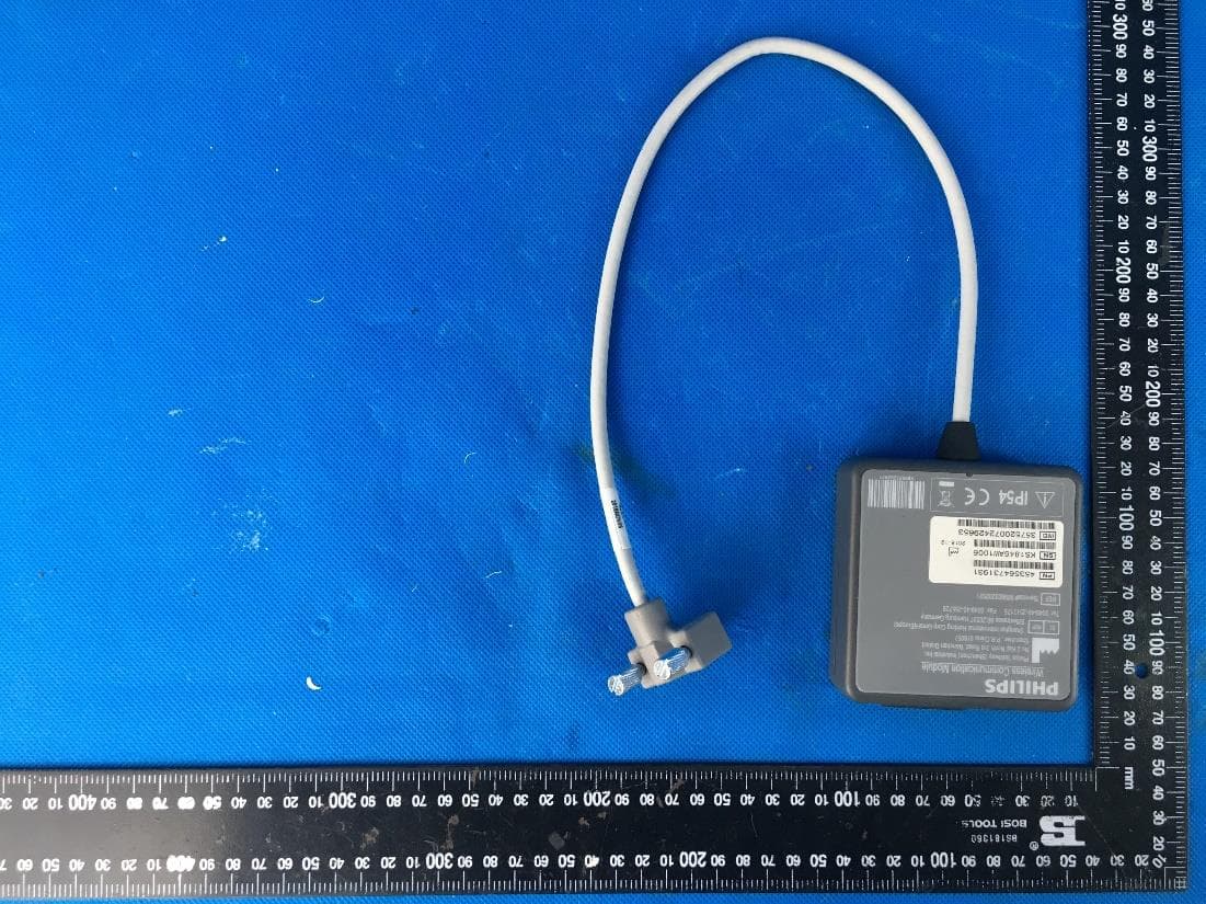
Click to zoom
Application Details
- Equipment Class
- PCB - PCS Licensed Transmitter
- Date of Grant
- Dec 02, 2020
- Application Purpose
- Original Equipment
- Date of Application
- Nov 30, 2020
- Equipment Note
- Wireless Communication Module
- Frequency Range
- 1852.40000000 - 1907.60000000
- Country
- China
Documents & Files
Document Text
Text extracted from the exhibit documents filed with the FCC. Open a document above to read the original.
Users Manual
Wireless Communication Module 989803202921 i Table of Contents ENGLISH . . . . . . . . . . . . . . . . . . . . . . . . . . . . . . . . . . . . . . . . . . . . . . . . . . . . . . . . . . . . . . . . . . . . . . . . 1 Table of Contents ii 1 Wireless Communication Module Introduction This document explains how to use the features of the HeartStart Intrepid’s Wireless Communication Module. The Wireless Communication Module (hereafter “Communication Module ”) allows the HeartStart Intrepid monitor/defibrillator to wirelessly transmit data such as 12-lead ECGs, vital signs data, and event summaries over cellular/mobile networks to Philips Emergency Care Informatics Suite. Setup and Connection SIM Card Installation To operate on cellular/mobile networks, the Communication Module must have a SIM (Subscriber Identification Module) card from your local cellular/mobile network provider installed. To install the SIM card: 1Open the rubber plug to access the SIM slot. 2Orient the SIM card beside the SIM slot. ENGLISH Connecting the Communication Module 2 3Push the SIM card into the slot until it is fully seated and latches. 4Close the rubber plug on the SIM slot. Connecting the Communication Module Depending on your carry case, place the Communication Module in either the rear pouch or side pouch. Figure 1 shows the rear pouch installation. The side pouch installation is similar. To connect the Communication Module to the HeartStart Intrepid: 1Feed the Communication Module cable through the opening in the pouch. 2On the HeartStart Intrepid, attach the cable to the connector. 3Tighten the thumb screws to ensure a good connection. Figure 1Connecting the Communication Module and the HeartStart Intrepid a. Unsnap the rear pouch from the HeartStart Intrepid, then insert the connector through the hole in the rear pouch. b. Plug the connector from the Communication Module into the device, and tighten the two thumb screws. d. Place the module in the rear pouch.c. Snap the rear pouch to the device. Connecting the Communication Module 3 4Turn on the HeartStart Intrepid. The green LED on the Communication Module is on. The orange LED periodically turns on and off during communication with the local cel lular/mobile network. Configuring Communication on the HeartStart Intrepid 4 Configuring Communication on the HeartStart Intrepid The HeartStart Intrepid defaults to Wi-Fi Mode. To configure the Intrepid for cellular wireless communication, ensure that the device is first switched to Cellular Mode. To configure the HeartStart Intrepid for cellular wireless communication: 1Press Smart Select knob, then from the Main Menu, choose . 2Press the Smart Sele ct knob again, choose , and then choose . 3Select to exit Clinical Mode, then press the Smart Select knob. 4From the Configuration menu , select . The screen is displayed. Figure 2Configuration - Cellular Connection Name Login Username Login Password Configuration - Cellular APN String 5Complete the fields with information described in the HeartStart Intrepid Instructions for Use Configuration chapter. Contact your cellular mobile network provider to obtain the correct Access Point Number (APN) for the APN field. Philips Emergency Care Informatics Suite To use the Communication Module to wirelessly send information, configure the HeartStart Intrepid with an optional Reference ID to identify the Intrepid device that is sending the information to Philips Emergency Care Informatics Suite. Contact a Philips representative to obtain an Emergency Care Informatics Suite account. To configure the HeartStart Intrepid for sending data: 1Press the Smart Sele ct knob. 2From the Main Menu, choose , then choose . 3Press the soft key to access the screen. The screen is displayed. Use the Smart Select knob in the following steps to navigate through the Communication screen. Sending Data with the Communication Module 5 Figure 3Configuration - Communication screen Reference ID Cloud URL Account ID Destination 1 Destination 2 Destination 3 Destination 4 Destination 5 Intrepid SN: CNX000999 EMS ID: 0225 https://www.philips-emergencycare.com CENTRE HOSPITALIER Enabled Enabled Disabled Disabled Disabled 902101 HOSPITAL GENERAL RIO CARRION Configuration - Communication 4Navigate to , and optionally enter a Reference ID (use the Smart Select knob to select a letter from the displayed keypad, then press the Smart Select knob to enter a letter). The Reference ID is not required, but may be used to identify the Intrepid device or the vehicle that the device is assigned to. 5Navigate to , then enter your Philips Emergency Care Informatics Suite URL. NOTE: The URL varies depending on your country and location. Obtain the correct URL from your Philips representative. 6Navigate to , then enter the six-character Philips Emergency Care Informatics Suite account ID. 7Use the Smart Select knob t o navigate to each Destination field as desired. The field contains the identification of the hospital or medical facility that has access to the data that is sent from the HeartStart Intrepid. The destination must be enabled in order for the HeartStart Intrepid to send data to that location. The Destination field is not required. If no destination is specified, the data is available only to the HeartStart Intrepid device owner. 8Optionally enter one or more destinations using the Smart Select knob as described above. Sending Data with the Communication Module Use the Communication Module to send data during patient care or following an event. During an event, 12-lead ECGs or vitals data can be sent. Following an event, the Event Summary can be sent. For more information on sending data, see the Data Management chapter in the HeartStart Intrepid Instructions for Use. NOTE: Successful transmission is dep…
Text truncated - open the document above for the full version.
External Photos
External photo
ID Label/Location Info
B D cu = +I M 0) - 6 C 9 [3]_[ 2 I I 3 - �-------- j L j��PC#,�lffl�,f�3M 9448; ��I I��,½ Chol k Gre 1. 6 1jl1fr t�JtijtJJ WT, �i!iffll b EDITION LABEL UPDATE DESIGNED Jl&;,js: 'lt:.l!!Jifti,R :l!lj!!{p;ji@'. i9:tt /:3'.!:J!:j!, p PfBI E PfBI L , ' .Ji: iFW lf�t r: I itK1 lf�t [ I If�* R'.l 7vJ ( PHILIPS IREFI 989803202921 Wireless Communication Module I -- Philips Goldway (Shenzhen) Industrial Inc. No.2 Keji North 3rd Road, Nanshan District, 518057, Shenzhen, PEOPLE'S REPUBLIC OF CHINA. Philips Medical Systems Nederland B.V. ( C IEC I REP I Veenpluis 6, 5684PC Best, The Netherlands � 0 DATE �fiBJ!/1 11-DCT -2017 OS-JJL -2018 10-�AY-2020 10-JJN-2020 07-DCT-2020 1 � IP54 R FCC ID: 2AWTR-03202921 � IC: 26273-03202921 • _ _ __ __ __ _ _ _ _ _ _ _ ��f� .. -- -- -- -- --- - - -- - -- - -- -- -- -- -- ---- I (' - Complies with IMDA J.I\ Standard � DB 100486 �f,'� [E[J PNlj,J'<JE11'! [ill SN'f,J'<JE11'! � IMEJ'f,J'<JE11'! � + LBL Intrepid 3G bottom cover Rev.E 71<1�� ��. ��±i�\!�7171 R-C-PCE-WBSONBT R-R-PCE-867172 oi9 -9--t:!�lllE ¥� �t!.ut�tl 7f{s{"!OI £!.% dLf) xxxx 11111 H J l l rn �ll , 11111! __. / 453564691641 Rev.E 11 I 11 453564691641 !l<%1"!1',1¥iU{o, HIRJ!!lj,(3{,, MATERIAL :rt 1'-4 PC Philips Goldway (Shenzhen) Industrial Inc. �.;t!J$Jli'�#.&ll (�.:tlll) �.llk.�JlEt�-€iJ PARTNO. 453564691641 PARTNAME 3G Bottom Cover Label PRODUCT 3G Module � ;ff); t" ® � DESIGNED lfit 07-OCT-2020 DWG NO . 453564691641-M-SPEC i9: tt 00£!\;ffi� CHE CKED PfBI EDITION M.S. QTY SC ALE SHE ET "' � 07- OCT-2020 It&* 00 �lli i/&m t� ¥ti J)[ ii& APPROVED 1ltt-f 07-OCT-2020 E A4 1 1:1 1 I 1 -ttt ll
Internal Photos
Internal photo Antenna Antenna port
RF Exposure Info
FCC REPORT Report Reference No. .................: CHTEW20070046 Report Verification: Project No.................................: SHT2006119501EW FCC ID......................................: 2AWTR-03202921 Applicant’s name .......................: Philips Goldway(Shenzhen) Industrial Inc. Address.................................... . : No.2 Keji North 3rd Road, Nanshan District, 518057, Shenzhen, China Manufacturer......................................: Philips Goldway(Shenzhen) Industrial Inc. Address..............................................: No.2 Keji North 3rd Road, Nanshan District, 518057, Shenzhen, China Test item description ..................: Wireless Communication Module Trade Mark................................ . : PHILIPS Model/Type reference.................. . : 989803202921 Listed Model(s) ...........................: - Standard.................................. : FCC Part 2.1091 Date of receipt of test sample..........: Jun. 28, 2020 Date of testing..............................: Jun. 29, 2020- Jul. 08, 2020 Date of issue...............................: Jul. 09, 2020 Result..........................................: Pass Compiled by ( position+printedname+signature) ... : File administrators Silvia Li Supervised by (position+printedname+signature) .... : Project Engineer Chengxiao Approved by (position+printedname+signature) .... : Manager Hans Hu Testing Laboratory Name ............. : Shenzhen Huatongwei International Inspection Co., Ltd. Address................ ......................... : 1/F, Bldg 3, Hongfa Hi-tech Industrial Park, Genyu Road, Tianliao, Gongming, Shenzhen, China Shenzhen Huatongwei International Inspection Co., Ltd. All rights reserved. This publication may be reproduced in whole or in part for non-commercial purposes as long as the Shenzhen Huatongwei International Inspection Co., Ltd. is acknowledged as copyright owner and source of the material. Shenzhen Huatongwei International Inspection Co., Ltd. takes no responsibility for and will not assume liability for damages resulting from the reader's interpretation of the reproduced material due to its placement and context. The test report merely correspond to the test sample. RF Exposure Evaluation LIMIT The criteria listed in the following table shall be used to evaluate the environment impact of human exposure to radio frequency (RF) radiation as specified in 1.1307(b) Limits for Maximum Permissible Exposure (MPE) Frequency range (MHz) Electric field strength (V/m) Magnetic field strength (A/m) Power density (mW/cm 2 ) Averaging time (minutes) (A) Limits for Occupational/Controlled Exposures 0.3–3.0 614 1.63 *(100) 6 3.0–30 1842/f 4.89/f *(900/f 2 ) 6 30–300 61.4 0.163 1.0 6 300–1500 - - f/300 6 1500–100,000 - - 5 6 (B) Limits for General Population/Uncontrolled Exposure 0.3–1.34 614 1.63 *(100) 30 1.34–30 824/f 2.19/f *(180/f 2 ) 30 30–300 27.5 0.073 0.2 30 300–1500 - - f/1500 30 1500–100,000 - - 1.0 30 Note: f = frequency in MHz EVALUATION METHOD Transmission formula: Pd = (Pout*G)/(4*pi*r 2 ) Where Pd = power density in mW/cm 2 , Pout = output power to antenna in mW, G = gain of antenna in linear scale; Pi = 3.1416, R = distance between observation point and center of the radiator in cm TEST RESULT Passed Not Applicable Type Maximum Tune-up (dBm) Conducted Average Power GSM850 30.71~32.71 PCS1900 27.00~29.00 WCDMA Band I 21.55~23.55 WCDMA Band VIII 21.29~23.29 Type Conducted Average Power (dBm) Maximum Tune-up (dBm) Power Density (mW/cm2) Limit (mW/cm2) Result GSM850 32.71 32.71 0.77398 1.0000 Pass PCS1900 29.00 29.00 0.33245 1.0000 Pass WCDMA Band II 23.55 23.55 0.09478 1.0000 Pass WCDMA Band V 23.29 23.29 0.08846 1.0000 Pass Note: 1) The maximum antenna gain is 3.23dBi 2) The exposure evaluation safety distance is 20cm.
Test Report
Page: 1 of 25 FCC REPORT Report Reference No. .................... : CHTEW20070044 Report Verification: Project No.................................: SHT2006119501EW FCC ID ............................................. : 2AWTR-03202921 Applicant’s name ........................... : Philips Goldway(Shenzhen) Industrial Inc. Address ............................................. : No.2 Keji North 3rd Road, Nanshan District, 518057, Shenzhen, China Manufacturer......................................: Philips Goldway(Shenzhen) Industrial Inc. Address..............................................: No.2 Keji North 3rd Road, Nanshan District, 518057, Shenzhen, China Test item description .................... : Wireless Communication Module Trade Mark ....................................... : PHILIPS Model/Type reference ....................... : 989803202921 Listed Model(s) ................................. : - Standard ......................................... : FCC CFR Title 47 Part 2 FCC CFR Title 47 Part 22 FCC CFR Title 47 Part 24 Date of receipt of test sample..........: Jun. 28, 2020 Date of testing..............................: Jun. 29, 2020- Jul. 08, 2020 Date of issue...............................: Jul. 09, 2020 Result .................. ........................: Pass Compiled by ( position+printedname+signature) ... : File administrators Silvia Li Supervised by (position+printedname+signature) .... : Project Engineer Chengxiao Approved by (position+printedname+signature) .... : Manager Hans Hu Testing Laboratory Name ............. : Shenzhen Huatongwei International Inspection Co., Ltd. Address ............................................. : 1/F, Bldg 3, Hongfa Hi-tech Industrial Park, Genyu Road, Tianliao, Gongming, Shenzhen, China Shenzhen Huatongwei International Inspection Co., Ltd. All rights reserved. This publication may be reproduced in whole or in part for non-commercial purposes as long as the Shenzhen Huatongwei International Inspection Co., Ltd. is acknowledged as copyright owner and source of the material. Shenzhen Huatongwei International Inspection Co., Ltd. takes no responsibility for and will not assume liability for damages resulting from the reader's interpretation of the reproduced material due to its placement and context. The test report merely correspond to the test sample. Report No.: CHTEW20070044 Page: 2 of 25 Issued: 2020-07-09 Shenzhen Huatongwei International Inspection Co., Ltd. Report Template Version: V01 (2018-01) Contents 1. TE S T S T AN D A R D S A N D R EP O R T V E R S I O N 3 1.1. Applicable Standards 3 1.2. Report version information 3 2. T E S T D E S C R I P T I O N 4 3. S U M M AR Y 5 3.1. VIIIClient Information 5 3.2. Product Description 5 3.3. Operation state 6 3.4. EUT configuration 6 3.5. Modifications 6 4. T E S T E N V I R O N M E N T 7 4.1. Address of the test laboratory 7 4.2. Test Facility 7 4.3. Equipments Used during the Test 8 4.4. Environmental conditions 9 4.5. Statement of the measurement uncertainty 9 5. T E S T C O N DI T I O N S A N D R E S U L T S 10 5.1. Conducted Output Power 10 5.2. Peak-to-Average Ratio 11 5.3. 99% Occupied Bandwidth & 26 dB Bandwidth 12 5.4. Modulation characteristics 13 5.5. Band Edge 14 5.6. Conducted Spurious Emissions 15 5.7. Frequency stability VS Temperature measurement 16 5.8. Frequency stability VS Voltage measurement 17 5.9. ERP and EIRP 18 5.10. Radiated Spurious Emission 21 6. A P P E N D I X R E P O R T 25 Report No.: CHTEW20070044 Page: 3 of 25 Issued: 2020-07-09 Shenzhen Huatongwei International Inspection Co., Ltd. Report Template Version: V01 (2018-01) 1. TEST STANDARDS AND REPORT VERSION 1.1. Applicable Standards The tests were performed according to following standards: FCC Rules Part 2: FREQUENCY ALLOCATIONS AND RADIO TREATY MATTERS; GENERAL RULES AND REGULATIONS FCC Rules Part 22: PUBLIC MOBILE SERVICES FCC Rules Part 24: PERSONAL COMMUNICATIONS SERVICES TIA/EIA 603 E March 2016: Land Mobile FM or PM Communications Equipment Measurement and Performance Standards. ANSI C63.26-2015: American National Standard for Compliance Testing of Transmitters Used in Licensed Radio Services KDB 971168 D01 Power Meas License Digital Systems v03: MEASUREMENT GUIDANCE FOR CERTIFICATION OF LICENSED DIGITAL TRANSMITTERS 1.2. Report version information Revision No. Date of issue Description N/A 2020-07-09 Original Report No.: CHTEW20070044 Page: 4 of 25 Issued: 2020-07-09 Shenzhen Huatongwei International Inspection Co., Ltd. Report Template Version: V01 (2018-01) 2. Test Description Test Item Section in CFR 47 Result Test Engineer Conducted Output Power Part 2.1046 Part 22.913(a) Part 24.232(c) Pass Peak-to-Average Ratio Part 24.232 Pass 99% Occupied Bandwidth & 26 dB Bandwidth Part 2.1049 Part 22.917(b) Part 24.238(b) Pass Modulation characteristics Part 2.1047 Pass Band Edge Part 2.1051 Part 22.917 Part 24.238 Pass Conducted Spurious Emissions Part 2.1051 Part 22.917 Part 24.238 Pass Frequency stability VS Temperature Part 2.1055(a)(1)(b) Part 22.355 Part 24.235 Pass Frequency stability VS Voltage Part 2.1055(d)(1)(2) Part 22.355 Part 24.235 Pass ERP and EIRP Part 22.913(a) Part 24.232(b) Pass Radiated Spurious Emissions Part 2.1053 Part 22.917 Part 24.238 Pass Note: The measurement uncertainty is not included in the test result. Report No.: CHTEW20070044 Page: 5 of 25 Issued: 2020-07-09 Shenzhen Huatongwei International Inspection Co., Ltd. Report Template Version: V01 (2018-01) 3. SUMM ARY 3.1. VIIIClient Information Applicant: Philips Goldway(Shenzhen) Industrial Inc. Address: No.2 Keji North 3rd Road, Nanshan District, 518057, Shenzhen, China Manufacturer: Philips Goldway(Shenzhen) Industrial Inc. Address: No.2 Keji North 3rd Road, Nanshan District, 518057, Shenzhen, China 3.2. Product Description Name of EUT: Wireless Communication Module Trade Mark: PHILIPS Model No.: 989803202921 Listed Model(s): - Power supply: 9-18V-+5% DC, Max 1.5A, normal Voltage DC12V Adapter information: - Hardware vers…
Text truncated - open the document above for the full version.
Test Setup Photos
Test setup photo Radiated spurious emission 30MHz-1GHz Radiated spurious emission above 1GHz
Contact Information
Applicant
Disment Yu
Test Firm
Shenzhen Huatongwei International Inspection Co.,Tony Jiang
[email protected]+86-755-26748078
Technical Specifications
| # | Rule Parts | Frequency Range | Power Output | Emission | Tolerance |
|---|---|---|---|---|---|
| 6 | 24E | 1.85 GHz - 1.91 GHz | 274.16 mW | 4M07F9W | 48.34 Hz |