Text extracted from the exhibit documents filed with the FCC. Open a document above to read the original.
p. 1 ・FCC ID display manual 2024/01/31 ① Top screen after startup. ② Press the menu key (bottom left of the Keyboard). ③ Screen after pressing the menu key. p. 2 ④ Press the right arrow key to move the menu cursor to Settings. ⑤ Press the Down arrow key, select Information, and press the Enter key. ⑥ Certification information (FCC ID and FCC logo) will be displayed.
Spec Sheet http://www.ty-top.com The data i s reference only. Electrical c haracteristics vary depending on environment or measurement condition. TAIYO YUDEN reserves t he right t o make change to the data at any t ime without notice. Before making final s election, please check product specification. Chip Antennas(Multilayer) TSA5N18D2G45NV001T (Previous PN: AH168M245001-T) Features Item Summary MonoPole, 1.6x0.8x0.65mm, for Bluetooth/W-LAN/ZigBee Lifecycle Stage Mass Production (Preferred) Standard packaging quantity (minimum) Taping Paper 5000pcs Products characteristics table SystemBluetooth/W-LAN/ZigBee Frequency Band Width2400 to 2500 MHz Center Frequency2450 MHz Gain1 (Peak Gain)(typ)+2.0 dBi Gain2 (Ave. Gain at OMNI plane)-1.5 dBi Efficiency (typ)-1.8 dB (66 %) VSWR (typ)3 TypeMonoPole Operating Temp. Range-40 to +85 °C RoHS Compliance (10 subst.)Yes REACH Compliance (235 subst.)Yes Halogen FreeYes SolderingReflow External Dimensions Dimension L1.6 ±0.1 mm Dimension W0.8 ±0.1 mm Dimension T0.65 max mm Dimension E0.3 ±0.1 mm Dimension b0.6 ±0.1 mm Dimension c0.4 ±0.1 mm 2024.01.29 Powered by TCPDF (www.tcpdf.org) 1 / 1 ■ Notice for TAIYO YUDEN Products Please read this notice before using the TAIYO YUDEN products. ⚠ REMINDERS ■ Approval of Product Specifications Please contact TAIYO YUDEN for further details of product specifications as the individual product specification sheets are available. When using our products, please be sure to approve our product specifications or make a written agreement on the product specification with TAIYO YUDEN in advance. Please note that TAIYO YUDEN shall not be in any way responsible for any damages and defects in products or equipment incorporating our products, which are caused under the conditions other than those specified in individual product specification sheets. ■ Pre-Evaluation in the Actual Equipment and Conditions Please conduct validation and verification of our products in actual conditions of mounting and operating environment before using our products. ■ Limited Application 1. Equipment Intended for Use Our products are intended for general-purpose and standard use in general electronic equipment for consumer (e.g., AV equipment, OA equipment, home electric appliances, office equipment, information and communication equipment including, without limitation, mobile phone, and PC) and other equipment specified in the product catalog or the individual product specification sheets, or the equipment approved separately by TAIYO YUDEN. TAIYO YUDEN has the product series intended for use in the following equipment. Therefore, when using our products for these equipment, please check available applications specified in the product catalog or the individual product specification sheets and use the corresponding products. Application Product Series Quality Grade *3 Equipment *1 Category (Part Number Code *2 ) Automotive Automotive Electronic Equipment (POWERTRAIN, SAFETY) A 1 Automotive Electronic Equipment (BODY & CHASSIS, INFOTAINMENT) C 2 Industrial Telecommunications Infrastructure and Industrial Equipment B 2 Medical Medical Devices classified as GHTF Class C (Japan Class III) M 2 Medical Devices classified as GHTF Classes A or B (Japan Classes I or II) L 3 Consumer General Electronic Equipment S 3 Only for Mobile Devices *4 E 4 *Notes: 1. Based on the general specifications required for electronic components for such equipment, which are recognized by TAIYO YUDEN, the use of each product series for the equipment is recommended. Please be sure to contact TAIYO YUDEN before using our products for equipment other than those covered by the product series. 2. On each of our part number, the 2nd code from the left is a code indicating the “Category” as shown in the above table. For details, please check the explanatory materials regarding the part numbering system of each of our products. 3. Each product series is assigned a “Quality Grade” from 1 to 4 in order of higher quality. Please do not incorporate a product into any equipment with a higher Quality Grade than the Quality Grade of such product without the prior written consent of TAIYO YUDEN. 4. The applications covered by this product series are limited to mobile devices (smartphone, tablet PC, smartwatch, handheld game console, etc.) among general electronic equipment for consumer. The design, specifications and operating environment, etc. differ from those of the product series for “General Electronic Equipment” (Category: S), so please check the individual product specification sheets for details. The product series for “General Electronic Equipment” (Category: S) can also be used for mobile devices. 2. Equipment Requiring Inquiry Please be sure to contact TAIYO YUDEN for further information before using our products for the following equipment (excluding intended equipment as specified in the product catalog or the individual product specification sheets) which may cause loss of human life, bodily injury, serious property damage and/or serious public impact due to a failure or defect of the products and/or malfunction attributed thereto. (1) Transportation equipment (automotive powertrain control system, train control system, and ship control system, etc.) (2) Traffic signal equipment (3) Disaster prevention equipment, crime prevention equipment (4) Medical devices classified as GHTF Class C (Japan Class III) (5) Highly public information network equipment, data-processing equipment (telephone exchange, and base station, etc.) (6) Any other equipment requiring high levels of quality and/or reliability equal to the equipment listed above 3. Equipment Prohibited for Use Please do not incorporate our products into the following equipment requiring extremely high levels of safety and/or reliability. (1) Aerospace equipment (artificial satellite, rocket, etc.) (2) Aviation equipment *1 (3) Medical devices classified as GHTF Class D (Japan Class IV), implantable medical devices *2 (4) P…
Text truncated - open the document above for the full version.
p. 1 ・FCC ID display manual 2024/01/31 ① Top screen after startup. ② Press the menu key (bottom left of the Keyboard). ③ Screen after pressing the menu key. p. 2 ④ Press the right arrow key to move the menu cursor to Settings. ⑤ Press the Down arrow key, select Information, and press the Enter key. ⑥ Certification information (FCC ID and FCC logo) will be displayed.
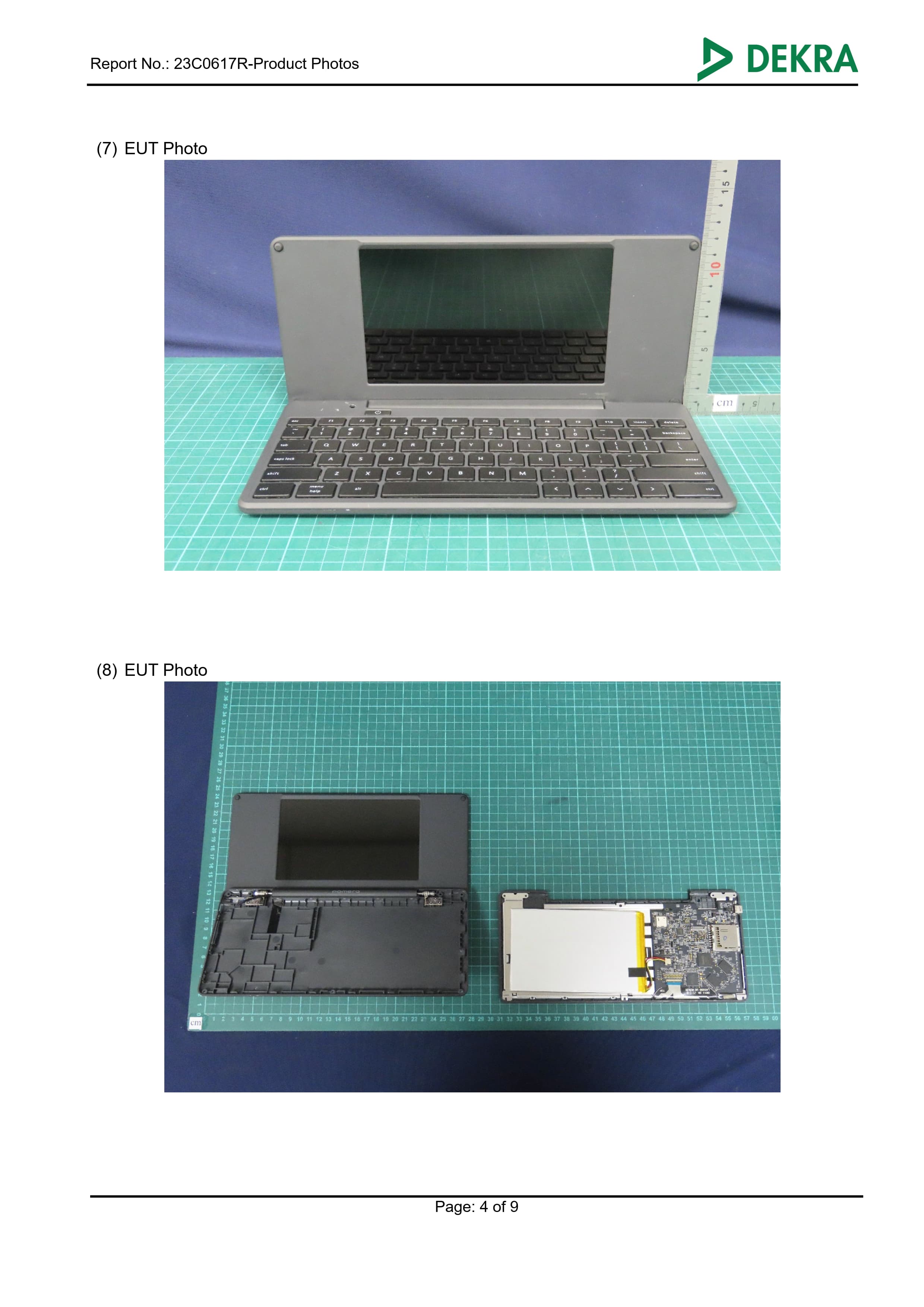
Report No.: 23C0617R-SAUSV01S-A Page: 1 of 27 Test report No.: 23C0617R-SAUSV01S-A SAR Test Report Product Name Digital Typewriter Trademark KING JIM Model and /or type reference DM250US Applicant ́s name / address KING JIM CO.,LTD. 2-10-18 Higashikanda,Chiyoda-ku Tokyo 101-0031 Japan Manufacturer ́s name KAGA MICRO SOLUTION CO.,LTD. FCC ID 2AWV4-DM250US Applicable Standard IEEE 1528-2013 KDB 447498 D01 v06 KDB 865664 D01 v01r04 Test Result Max. SAR Measurement (1g) 2.4 GHz: 0.093 W/kg Verdict Summary IN COMPLIANCE Documented By (Senior Project Specialist / Ida Tung) Te s t e d B y (Senior Engineer / Luke Cheng) Approved By (Assistant Manager / San Lin) Date of Receipt 2023/12/18 Date of Issue 2024/02/15 Report Version V1.0 Report No.: 23C0617R-SAUSV01S-A Page: 2 of 27 INDEX Page 1. General Information ........................................................................................................ 5 1.1 EUT Description ................................................................................................. 5 1.2 Antenna List ....................................................................................................... 5 1.3 SAR Test Exclusion Calculation ......................................................................... 6 1.4 Test Environment ................................................................................................ 7 1.5 Measurement procedures................................................................................... 8 2. SAR Measurement System ............................................................................................. 9 2.1 DASY System Description .................................................................................. 9 2.2 Area Scans ....................................................................................................... 10 2.3 DASY E-Field Probe ......................................................................................... 11 2.4 DATA Acquisition Electronics (DAE) and Measurement Server ........................ 12 2.5 Robot ................................................................................................................ 13 2.6 Device Holder ................................................................................................... 13 2.7 Phantom ........................................................................................................... 14 3. Tissue Simulating Liquid .............................................................................................. 15 3.1 The composition of the tissue simulating liquid ................................................ 15 3.2 Tissue Calibration Result .................................................................................. 15 3.3 Tissue Dielectric Parameters for Phantoms ..................................................... 16 4. Measurement Procedure ............................................................................................... 17 4.1 SAR System Check .......................................................................................... 17 4.2 SAR Measurement Procedure .......................................................................... 18 5. RF Exposure Limits ....................................................................................................... 19 6. Test Equipment List ...................................................................................................... 20 7. Measurement Uncertainty ............................................................................................. 22 8. Conducted Power Measurement (Including tolerance allowed for production unit) ......................................................................................................................... 24 9. Test Results ................................................................................................................... 26 9.1 Test Results Summary ..................................................................................... 26 Appendix A. System Check Data Appendix B. Highest measurement Data Appendix C. Test Setup Photographs Appendix D. Probe Calibration Data Appendix E. Dipole & Source Calibration Appendix F. Product Photos-Please refer to the file: 23C0617R-Product Photos Report No.: 23C0617R-SAUSV01S-A Page: 3 of 27 Competences and Guarantees DEKRA is a testing laboratory competent to carry out the tests described in this report. In order to assure the traceability to other national and international laboratories, DEKRA has a calibration and maintenance program for its measurement equipment. DEKRA guarantees the reliability of the data presented in this report, which is the result of the measurements and the tests performed to the item under test on the date and under the conditions stated in the report and it is based on the knowledge and technical facilities available at DEKRA at the time of performance of the test. DEKRA is liable to the client for the maintenance of the confidentiality of all information related to the item under test and the results of the test. The results presented in this Test Report apply only to the particular item under test established in this document. IMPORTANT: No parts of this report may be reproduced or quoted out of context, in any form or by any means, except in full, without the previous written permission of DEKRA. General conditions 1. The test results relate only to the samples tested. 2. The test results shown in the test report are traceable to the national/international standard through the calibration report of the equipment and evaluated measurement uncertainty herein. 3. This report must not be used to claim product endorsement by TAF or any agency of the government. 4. The test report shall not be reproduced without the written approval of DEKRA Testing and Certification Co., Ltd. 5. Measurement uncertainties evaluated for each testing system and associated connecti…
Text truncated - open the document above for the full version.
TÜV SÜD Japan Ltd. Yonezawa Testing Center 5-4149-7 Hachimanpara, Yonezawa-shi, Yamagata, 992-1128 Japan Phone: +81 (0) 238 28 2881 www.tuvsud.com/ja-jp TÜV SÜD Japan Ltd. Report on the RF Testing of: KING JIM CO., LTD. Digital Typewriter “pomera”, Model: DM250US FCC ID: 2AWV4-DM250US In accordance with FCC Part15 Subpart C Prepared for: KING JIM CO., LTD. 2-10-18, Higashi-Kanda, Chiyoda-ku, Tokyo, 101-0031, Japan Phone: +(81) 3-3864- 8080 COMMERCIAL-IN-CONFIDENCE Document Number:JPD-TR-24003-0 SIGNATURE NAMEJOB TITLERESPONSIBLE FORISSUE DATE Hiroaki SuzukiDeputy Manager of RF GroupApproved Signatory Signatures in this approval box have checked this document in line with the requirements of TÜV SÜD Japan Ltd. document control rules. EXECUTIVE SUMMARY – Result: Complied A sample of this product was tested and the result above was confirmed in accordance withFCC Part15 Subpart C. DISCLAIMER AND COPYRIGHT The results in this report are applicable only to the equipment tested. This report shall not be re-produced except in full without the written approval of TÜV SÜD Japan Ltd. Client provided data, for which TÜV SÜD Japan Ltd. take no responsibility, which can affect validity of results within this report is clearly identified. ACCREDIATION This test report must not be used by the client to claim product certification, approval, or endorsement by A2LA or any agency of the U.S. Government. Document Number: JPD-TR-24003-0 TÜV SÜD Japan Ltd. Page 2 of 72 Contents 1Summary of Test .................................................................................................................... 3 1.1Modification history of the test report ........................................................................................ 3 1.2Standards ................................................................................................................................ 3 1.3Test methods ........................................................................................................................... 3 1.4Deviation from standards.......................................................................................................... 3 1.5List of applied test(s) of the EUT............................................................................................... 3 1.6Test information ....................................................................................................................... 3 1.7Test set up ............................................................................................................................... 3 1.8Test period ............................................................................................................................... 3 2Equipment Under Test ........................................................................................................... 4 2.1EUT information ....................................................................................................................... 4 2.2Modification to the EUT ............................................................................................................ 5 2.3Variation of family model(s) ...................................................................................................... 5 2.4Operating channels and frequencies ........................................................................................ 5 2.5Description of test mode ........................................................................................................... 6 2.6Operating flow .......................................................................................................................... 6 3Configuration of Equipment .................................................................................................. 7 3.1Equipment used ....................................................................................................................... 7 3.2Cable(s) used........................................................................................................................... 7 3.3System configuration ................................................................................................................ 7 4Test Result ............................................................................................................................. 8 4.1DTS Bandwidth / Occupied Bandwidth (99%) ........................................................................... 8 4.2Maximum Conducted Output Power ....................................................................................... 13 4.3Band Edge Compliance of RF Conducted Emissions .............................................................. 15 4.4Spurious Emissions - Conducted - .......................................................................................... 20 4.5Spurious Emissions - Radiated -............................................................................................. 31 4.6Restricted Band of Operation ................................................................................................. 52 4.7Transmitter Power Spectral Density........................................................................................ 60 4.8AC Power Line Conducted Emissions .................................................................................... 65 5Antenna requirement ........................................................................................................... 68 6Measurement Uncertainty .................................................................................................... 69 7Laboratory Information ........................................................................................................ 70 Appendix A. Test Equipment ............................................................................................................... 71 Appendix B. Duty Cycle .........................................…
Text truncated - open the document above for the full version.
KING JIM CO., LTD. FCC ID: 2AWV4-DM250US Radiated Emission 30MHz to 200MHz 200MHz to 1GHz Above 1GHz KING JIM CO., LTD. FCC ID: 2AWV4-DM250US X-axis Y-axis Z-axis Note: X-axis, generates the maximum emission at Bluetooth. Y-axis, generates the maximum emission at WLAN 2.4GHz. KING JIM CO., LTD. FCC ID: 2AWV4-DM250US AC Power Line Conducted Emission KING JIM CO., LTD. FCC ID: 2AWV4-DM250US Antenna port Conducted Test
| # | Rule Parts | Frequency Range | Power Output |
|---|---|---|---|
| 1 | 15C | 2.41 GHz - 2.46 GHz | 219.00 mW |