2AWYMKALLOSWearable safety and wellness solution for senior communities
Intrex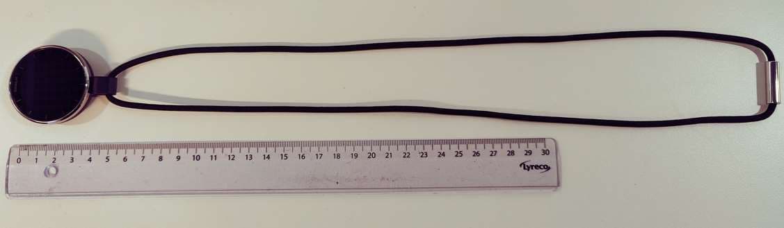
Click to zoom
Application Details
- Equipment Class
- DTS - Digital Transmission System
- Date of Grant
- Sep 24, 2024
- Application Purpose
- Original Equipment
- Date of Application
- Sep 24, 2024
- Equipment Note
- Wearable safety and wellness solution for senior communities
- Frequency Range
- 2402.00000000 - 2480.00000000
- Company
- Intrex
- Country
- United States
Documents & Files
Document Text
Text extracted from the exhibit documents filed with the FCC. Open a document above to read the original.
Users Manual
1 Rythmos® Kallos – User Guide (DRAFT) Rythmos® Kallos Quick Quide First Use 1. Takes a device and suitable holder (wrist or pendant) 2. Turn the power on by holding the side buƩon for a few seconds. 3. The device shows unit QR -code on the screen. 4. Read the QR code from the display to idenƟfy the device. 5. Check resident’s profile from the Rythmos system. 6. Assign the device to the resident by puƫng the code in their seƫngs. 7. The device updates with resident’s chosen pictures and personal seƫngs a. Resident profile to include: i. Personal picture chosen and given by the resident. ii. Unit sensiƟvity (push seƫngs) iii. Unit mode (Independ Living, Assistance Living, Memory Care, Standalone) iv. Watch style (wrist or pendant) v. Onboarding compleƟon vi. Ability to cancel the emergency call vii. Digital or analog clock/Ɵme viii. Wrist or pendant use opƟon 8. The device is ready to give to the resident. ConƟnue to read the detailed instrucƟons. User and InstallaƟon Guide v. 0.01 General InformaƟon Kallos product is a baƩery-operated single wearable device to provide following main features: 1. Nurse Call 2. Real-Time LocaƟon 3. Fall DetecƟon 4. Access Control 5. Digital /analog funcƟoning watch 6. Customizable with pictures (love ones) 2 Product is one device in Rythmos+ Community System, Safety and Wellness soluƟon for senior communiƟes. Device has two use-case, wrist use and pendant use. Variants are changeable by two different holders. The device itself does not vary. Accessories 1. Individual charger 2. Holder for the wrist bands 3. Standard wrist bands 4. Holder for the necklace 5. Standard necklace Using of holders 1. Wrist band holder Set the side buƩon to the same locaƟon as the cavity of the holder and press down carefully unƟl the device is locked on the holder. Removing from the holder can be done by fingernail or flat tool by which can be open the snap contact of the holder without damaging it. Put the fingernail or flat tool behind the snap contact and bend it to outside at the same Ɵme pressing the device from the boƩom. 3 2. Pendant holder Seƫng the pendant holder is done the same way as wrist band holder. Set the side buƩon to the same locaƟon as the cavity of the holder and press down carefully unƟl the device is locked on the holder. Removing from the pendant holder is also done the same way as wrist band holder. The difference is that there is more space around snap contact. Put the fingernail or flat tool behind the snap contact and bend it to outside at the same Ɵme pressing the device from the boƩom. Using of Kallos Device Kallos is an advanced wearable, featuring locaƟon informaƟon within and outside the community, unobtrusive fall detecƟon, an OLED display with analog or digital watch, nurse call buƩon in display, possibility to add love ones pictures, waterproof design, and mulƟple wear styles. Kallos including access control also inside of the communiƟes. Kallos can be changed to different user profiles, such as Independ Living, Assistance Living, Memory Care and Stand Alone. This will be chosen when first use of device is in progress. Kallos has two use case opƟons as wrist use and pendant use. This needs to be chosen from Rythmos system during First Use procedure. 4 Onboarding First use Ɵme start the onboarding flow so the unit can be tested, and the user can learn how to use the device. Onboarding flow will be defined by user seƫngs in their profile. 1. Press the buƩon to move from the screen to the next one. 2. Use of side buƩon for viewing pictures. Picture will display for 20 seconds and if there are mulƟple pictures a side buƩon will be used to look at the next picture. 3. Use of screen buƩon for starƟng emergency call. When user starts pressing the screen, the device starts emergency “call”. With vibraƟon and audio. 3 seconds countdown is shown on screen, vibraƟon with each count and audio countdown. 5 Before the call starts a distress signal is sent. Distress signal is sent even if the call funcƟon is disabled. AŌer the call is picked up by a caregiver, unit displays ongoing call state with the duraƟon of the call. Call can be ended with the side buƩon. 4. Next step is Fall detecƟon. View of fall detecƟon and emergency call cancellaƟon. Emergency call starƟng in 30 seconds. 6 Use press and hold side buƩon to cancel emergency call. If the user cancels the call unit displays call cancelled view. This view can be closed with the side buƩon or 5 second Ɵmeout. 5. Use if incoming call, answer with screen buƩon. End call with the side buƩon. 6. All of needed onboarding completed and the unit is ready to be used normally. Press the side buƩon to move to watch face. 7 User Guide Viewing Pictures User has possibility to view pictures from the device if given pictures are downloaded into Rythmos system to the resident's profile. Press the side buƩon. Personal pictures showing for 20 seconds, if there are mulƟple pictures the side buƩon is used to switch to next one. AŌer 20 second of last press of the side buƩon, the display goes back to Ɵme view. Individual Charging Low baƩery icon displays when the device has 10% baƩery leŌ. Low baƩery noƟficaƟon is shown to the user accompanied by vibraƟon. This view can be closed by using the side buƩon. The low baƩery icon will conƟnue showing unƟl the device is charged. Individual charger requires USB-C type cable and external power source. The power source’s output recommendaƟon is 5V/2A. 8 1. Ensure that the power source’s output power is good enough for the charging (min. 5V/500mA) 2. Connect USB-C cable into charger. 3. Place the individual charger below the Kallos device. The posiƟon of the individual charger is shown in the picture below. The individual charger and the Kallos device have magnets in both units that guide the charger to the correct posiƟon. 4. Charging is ongoing when the device will display charging view. 5. When the baƩery is full, the device will display the full baƩery state unƟl it is taken off c…
Text truncated - open the document above for the full version.
Cover Letter(s)
Federal Communications Commission Authorization and Evaluation Division Equipment Authorization Branch 7435 Oakland Mills Road Columbia, MD 21046 6/5/24 U.S. Agent Designation Intrex Inc. acknowledges their consent for the following contact located in the United States to act as their agent for service of process for the equipment for which authorization is sought (FCC ID: 2AWYMKALLOS): Name and company of U.S. agent: Intrex Inc. Physical U.S. address of agent:1896 Preston White Dr., Reston, VA 20191 FRN of U.S. agent:0029776036 Email address of U.S. agent: [email protected] Intrex Inc. acknowledges their obligation to accept service of process on behalf of Intrex Inc.. Intrex Inc. with the FRN 0029776036 accepts its obligation to maintain an agent for service of process in the United States for no less than one year after either the grantee has permanently terminated all marketing and importation of the applicable equipment within the U.S., or the conclusion of any Commission-related administrative or judicial proceeding involving the equipment, whichever is later. By signing this form, we confirm the above and that we are aware of the application requirements listed under § 2.911(d)(7). The information provided in this letter is based on the referenced rule parts of Title 47 of the CFR as well as KDB 986446 D01. An expiration date for this letter does not exist. In case the U.S. agent changes, the grantee is obligated to notify the FCC within 30 days via the granting TCB. Sincerely, Signature Ted Tzirimis Chief Executive Officer Intrex Inc. Signature Lacy Roberts Director of Operations Intrex Inc. 48_[mo del] US_Agent_2.911(d)(7) - U, V05
Cover Letter(s)
Date: 2024-06-05 Federal Communication Commission Authorization and Evaluation Division Equipment Authorization Branch 7435 Oakland Mills Road Columbia, MD 21046 Statement of re-use of original test results of approved radio modules according to KDB 996369 D02 Module Q and A v01 Q1(a) Reference of new FCC ID application: Applicant: Intrex Inc. FCC ID: 2AWYMKALLOS We, the undersigned, hereby declare that our radio device hosts the following approved radio module(s) Grantee: Quectel Wireless Solutions Company Limited Type of Module: LTE Cat M1 FCC ID: XMR201912BG77 Report Reference R1909A0576 Grantee: Type of Module: FCC ID: Report Reference The module(s) is/are installed according to the installation instructions of the module manufacturer(s) without modification. The original module test report(s) accurately represent all conducted measured test results under the new conditions. All radiated measurements according to the applicable radio standard(s), the rf-exposure and simultaneous transmission evaluation are performed and reported for the entire host. Sincerely, Signature Ted Tzirimis Chief Executive Officer Intrex Inc.
Cover Letter(s)
Federal Communications Commission Authorization and Evaluation Division Equipment Authorization Branch 7435 Oakland Mills Road Columbia, MD 21046 6/5/24 To whom it may concern: We, the undersigned, hereby authorize Eurofins Product Service GmbH to act on our behalf in all matters relating to applications for equipment authorization FCC ID: 2AWYMKALLOS including the signing of all documents related to these matters. Any and all acts carried out by Eurofins Product Service GmbH on our behalf shall have the same effect as acts of our own. By signing this application form, we agree to Eurofins’ current valid General Terms and Conditions (AGB),Testing and Certification Regulations (PZO) which can be viewed on following website www.eurofins.de/ee or retrieved on request. We also hereby certify that no party to this application is subject to a denial of benefits, including FCC benefits, pursuant to Section 5301 of the Anti-Drug Abuse Act of 1988, 21 U.S.C. 862. Sincerely, Signature Ted Tzirimis Chief Executive Officer Intrex Inc.
Cover Letter(s)
05_G0M22405 - 0003_134461 ConReq - U_V02_ready_for_sign_2.doc 1/2 Federal Communications Commission Equipment Authorization Branch 7435 Oakland Mills Road Columbia, MD 21046 6/5/24 Request for Confidentiality Company name: Intrex Inc. FCC ID: 2AWYMKALLOS In accordance with CFR 47 §0.457(d) and CFR 47 §0.459 of the Commission’s Rules, Intrex Inc. hereby requests confidentiality of following exhibits: Exhibit Type: Type of Confidentiality Requested Detailed block diagrams* x Long-term confidentiality Schematic diagrams* x Long-term confidentiality Detailed operational descriptions* x Long-term confidentiality Parts lists/ tune up information* x Long-term confidentiality External photos - Short-term confidentiality** Internal photos - Short-term confidentiality** Test setup photos - Short-term confidentiality** User’s manual - Short-term confidentiality** Short-term maximum confidentiality period: 180 days OR: Short-term confidentiality release date (product launch): MM/DD/YYYY * Exhibits not routinely made available to the public. ** Only if applicable: Short-Term Confidentiality can be requested for a maximum of 180 days from the date of the grant. When the device is marketed the grantee must inform the TCB to release the Short-Term Confidentiality information withheld on the FCC equipment authorization website. 05_G0M22405 - 0003_134461 ConReq - U_V02_ready_for_sign_2.doc 2/2 Long-term confidentiality: The documents indicated as long- term confidential contain detailed system and equipment description and related information about the product which Intrex Inc. considers to be proprietary, confidential and a custom design and the information is not publicly available. Since the design is a basis from which future technological products will evolve, Intrex Inc. considers that this information would be of benefit to its competitors and that the disclosure of the information in these documents would give competitors an unfair advantage in the market. Short-term confidentiality (if applicable): Intrex Inc. requests the exhibits selected above as short-term confidential to be withheld from public view for the period as indicated above. When the device is marketed, Intrex Inc. will inform the TCB to release the short-term confidentiality information withheld on the FCC equipment authorization website. Sincerely, Signature Ted Tzirimis Chief Executive Officer Intrex Inc. 1896 Preston White Dr. Reston, VA 20191
External Photos
KALLOS Deviceexternal pictures FrontBack RightLeft KALLOS Device with wristbands Front Back Left Right KALLOS Device with pendant Front Back LeftRight
ID Label/Location Info
Label Sample KALLOS
ID Label/Location Info
Label Loc KALLOS
Internal Photos
KALLOS Device internal pictures Front Display unit dissambled Connector disconnected KALLOS Device internal pictures Frontview inside Device from inside Cellularmodulelabel KALLOS Device internal pictures Antennaframeremoved BT & GNSS Antenna frame front LTE Antenna and BT & GNSS antenna frame BT & GNSS Antenna frame back KALLOS Device internal pictures PCB top PCB bottom PCB top without RF shields KALLOS Device internal pictures Battery assembled Battery removed top Battery removed bottom KALLOS Device internal pictures Bottom cover inside Bottom cover outside
RF Exposure Info
1 (83) Copyright © Verkotan 2024 Document ID: FCC ISED_SAR report_KALLOS ID6399b_03052024.docx SAR Compliance Test Report Date of Report 3/05/2024 Client’s Contact person: Lacy Roberts Number of pages: 83 Responsible Test engineer: Jesper Varis Testing laboratory: Verkotan Oy Elektroniikkatie 17 90590 Oulu Finland Client: Intrex Inc. 1896 Preston White Drive VA 20191 Reston USA Tested device Wander Management wearable for elderly care/senior living Related reports: - Testing has been carried out in accordance with: 47CFR §2.1093 Radiofrequency Radiation Exposure Evaluation: Portable Devices FCC published RF exposure KDB procedures IEC/IEEE 62209-1528, 2020 Measurement procedure for the assessment of specific absorption rate of human exposure to radio frequency fields from hand-held and body-mounted wireless communication devices RSS-102, Issue 5, 2015 Radio Frequency (RF) Exposure Compliance of Radiocommunication Apparatus (All Frequency Bands) Documentation: The test report must always be reproduced in full; reproduction of an excerpt only is subject to written approval of the testing laboratory Test Results: The EUT complies with the requirements in respect of all parameters subject to the test. The test results relate only to devices specified in this document Date and signatures: 03.05.2024 Laboratory Manager 2 (83) Copyright © Verkotan 2024 Document ID: FCC ISED_SAR report_KALLOS ID6399b_03052024.docx TABLE OF CONTENTS 1. SUMMARY OF SAR TEST REPORT .................................................................................................................................. 3 1.1 TEST DETAILS .................................................................................................................................................................................................... 3 1.2 MAXIMUM RESULTS ...................................................................................................................................................................................... 4 1.2.1 Standalone SAR.......................................................................................................................................................................................... 4 1.2.2 Maximum Drift ............................................................................................................................................................................................ 4 1.2.3 Measurement Uncertainty .................................................................................................................................................................... 5 2. DESCRIPTION OF THE DEVICE UNDER TEST (DUT) ...................................................................................................... 6 2.1 SUPPORTED FREQUENCY BANDS AND OPERATIONAL MODES ................................................................................................ 7 2.2 SIMULTANEOUS TRANSMISSION ............................................................................................................................................................ 7 3. OUTPUT POWER ............................................................................................................................................................... 8 3.1 MAXIMUM SPECIFIED CONDUCTED OUTPUT POWER................................................................................................................... 8 3.2 TESTED CONDUCTED POWER ................................................................................................................................................................... 8 4. TEST EQUIPMENT .......................................................................................................................................................... 17 4.1 TEST EQUIPMENT LIST ................................................................................................................................................................................ 18 4.1.1 Isotropic E-field Probe Type EX3DV4.............................................................................................................................................. 19 4.2 PHANTOMS ..................................................................................................................................................................................................... 19 4.3 TISSUE SIMULANTS ...................................................................................................................................................................................... 20 4.4 SYSTEM VALIDATION STATUS ................................................................................................................................................................ 20 4.5 SYSTEM CHECK .............................................................................................................................................................................................. 21 4.5.1 Tissue Simulant Verification ................................................................................................................................................................ 22 5. TEST PROCEDURE .......................................................................................................................................................... 23 5.1 DEVICE HOLDER ............................................................................................................................................................................................ 24 5.2 TEST POSITIONS ............................................................................................................................................................................................ 24 5.2.1 Body-worn Configuration & Wristband Next-to-Mouth, 5mm separation distance ................................................. 24 5.2.2…
Text truncated - open the document above for the full version.
Test Report
Provided by Eurofins Product Service GmbH v.0. 2 Declaration concerning Antenna Specification It is hereby declared that the product Model No.: KALLOS FCC ID: 2AWYMKALLOS fulfills the requirement in FCC test relating to the antenna type. The device specified above confirms to the FCC recommendations for internal antenna type described below: Model No. 1 of antenna (Cellular): LDS Type of antenna: Build into housing. Peak Gain of the antenna: -7.4 dBi Frequency range: 698 - 960 / 1710 - 2200 MHz The mounting of the antenna is fixed to the radio module and no other antenna should be used. Model No. 2 of antenna (Bluetooth Low Energy): LDS Type of antenna: Build into housing. Peak Gain of the antenna: -8.9 dBi Frequency range: 2400 - 2480 MHz The mounting of the antenna is fixed to the radio module and no other antenna should be used. Model No. 3 of antenna (GNSS): LDS Type of antenna: Build into housing. Peak Gain of the antenna: -5.5 dBi Frequency range: 1560 - 1606 MHz Company name: Intrex Inc. Address: 1896 Preston White Dr. City: Reston ZIP / Postal code: VA 20191 Country: USA Provided by Eurofins Product Service GmbH v.0. 2 Place: Reston Date: 20 th of May, 2024 Signature: Ted Tzirimis
Test Report
Eurofins Electric & Electronics Finland Oy, Yrttipellontie 6, FI-90230 OULU Tel. +358 40 631 1311 Radio Test Report According to FCC part 15C, RSS-247, RSS-Gen DUT Name: KALLOS Model No: KALLOS Customer: Intrex Inc Address: 1896 Preston White Drive, 20191, Reston, VA, United States Summary IN COMPLIANCE Date of Reception: 28.3.2024 Date(s) of Test(s): 8.4.2024 – 29.4.2024 Tested by Test Engineer Approved by Technical Manager The test report shall not be reproduced except in full, without the written approval of the laboratory. This report is only for the equipment which is described in page 4. Test report number: 3941RER001 Page 2 (60) Date of issue: 12-Jun-24 Eurofins Electric & Electronics Finland Oy, Yrttipellontie 6, FI-90230 OULU Tel. +358 40 631 131 CONTENTS 1. General Information .............................................................................................................................................................. 3 2. Test Samples .......................................................................................................................................................................... 4 3. Configuration and Operation Modes .................................................................................................................................... 6 4. Test equipment...................................................................................................................................................................... 7 5. Uncertainties ......................................................................................................................................................................... 8 7. Test conditions .................................................................................................................................................................... 10 8. Summary .............................................................................................................................................................................. 13 9. Occupied bandwidth ........................................................................................................................................................... 14 10. 6 dB bandwidth ................................................................................................................................................................. 16 11. Peak conducted output power .......................................................................................................................................... 18 12. Peak Power Spectral Density ............................................................................................................................................. 20 13. AC power line conducted emissions .................................................................................................................................. 22 14. Band edge emissions compliance (transmitter) ................................................................................................................ 25 15. Tx spurious emissions, conducted ..................................................................................................................................... 28 16. Emissions in restricted frequency bands ........................................................................................................................... 31 17. Tx spurious emissions, radiated ........................................................................................................................................ 35 18. Receiver spurious emissions, radiated .............................................................................................................................. 48 19. Photographs – Equipment External ................................................................................................................................... 51 20. Photographs – Equipment Internal ................................................................................................................................... 54 21. Photographs – Test Setups ................................................................................................................................................ 56 Document Version History Date of issue Comments Approved by v0.1 7.6.2024 Initial version v1.0 12.6.2024 Approved version Jukka Rauma Test report number: 3941RER001 Page 3 (60) Date of issue: 12-Jun-24 Eurofins Electric & Electronics Finland Oy, Yrttipellontie 6, FI-90230 OULU Tel. +358 40 631 131 1. General Information Test Engineers: Arto Kuosmanen, Pekka Pulkkinen Location: Test Firm Name Eurofins Electric & Electronics Finland Oy (EEEF) Test Site Yrttipellontie, Peltola Address of Test Site Yrttipellontie 6, 90230 Oulu, Finland FCC Designation number FI0008 FCC site registration number 771880 ISED number 29576 CAB Identifier T290 Customer: Intrex Inc Ted Tzirimis 1896 Preston White Drive, 20191, Reston, VA, United States tel: +17034833255 e-mail: [email protected] Climate Conditions: Temperature: 15 - 35 °C Air pressure: 860 - 1060 hPa Humidity: 30-60 rH% These limits were not exceeded during testing. Test report number: 3941RER001 Page 4 (60) Date of issue: 12-Jun-24 Eurofins Electric & Electronics Finland Oy, Yrttipellontie 6, FI-90230 OULU Tel. +358 40 631 131 2. Test Samples General description: Product is one device in Rythmos+ community system. Safety and wellness solution for senior communities. Test sample (Conducted RF): Sample number Serial number Manufacturer DUT Type Model HW version SW version 3941ER002 MDR_04_02_12 Intrex Inc Wearable safety and wellness device KALLOS MRD_04 2024.03.1x.1 Test sample (Radiated and conducted emissions): Sample number Serial number Manufacturer DUT Type Model HW version SW version 3941ER004 MRD_04_01_1 Intrex Inc Wearable safety and wellness device KALLOS MRD_04 2024.03.1x.1 3941ER005 M…
Text truncated - open the document above for the full version.
Test Report
Eurofins Electric & Electronics Finland Oy, Yrttipellontie 6, FI-90230 OULU Tel. +358 40 631 1311 Radio Test Report According to FCC part 15C, RSS-247, RSS-Gen DUT Name: KALLOS Model No. : KALLOS Customer: Intrex Inc Address: 1896 Preston White Drive, 20191, Reston, VA, United States Summary IN COMPLIANCE Date of Reception: 28.3.2024 Date(s) of Test(s): 8.4.2024 – 29.4.2024 Tested by Test Engineer Approved by Technical Manager The test report shall not be reproduced except in full, without the written approval of the laboratory. This report is only for the equipment which is described in page 4. Test report number: 3941RER002 Page 2 (59) Date of issue: 14-Jun-24 Eurofins Electric & Electronics Finland Oy, Yrttipellontie 6, FI-90230 OULU Tel. +358 40 631 131 CONTENTS 1. General Information .............................................................................................................................................................. 3 2. Test Samples .......................................................................................................................................................................... 4 3. Configuration and Operation Modes .................................................................................................................................... 6 4. Test equipment...................................................................................................................................................................... 7 5. Uncertainties ......................................................................................................................................................................... 8 6. Sample emission level calculation ......................................................................................................................................... 9 7. Test conditions .................................................................................................................................................................... 10 8. Summary .............................................................................................................................................................................. 13 9. Occupied bandwidth ........................................................................................................................................................... 14 10. 6 dB bandwidth ................................................................................................................................................................. 16 11. Peak conducted output power .......................................................................................................................................... 18 12. Peak Power Spectral Density ............................................................................................................................................. 20 13. AC power line conducted emissions .................................................................................................................................. 22 14. Band edge emissions compliance (transmitter) ................................................................................................................ 25 15. Tx spurious emissions, conducted ..................................................................................................................................... 28 16. Emissions in restricted frequency bands ........................................................................................................................... 31 17. Tx spurious emissions, radiated ...................................................................…
Text truncated - open the document above for the full version.
Contact Information
Applicant
Ted Tzirimis(CTO)
Technical Contact
Test Firm
Eurofins Electric & Electronics Finland Oy (EEEF)Jukka Rauma
[email protected]358440451088
Technical Specifications
| # | Rule Parts | Frequency Range | Power Output |
|---|---|---|---|
| 1 | 15C | 2.40 GHz - 2.48 GHz | 1.00 mW |