2AWYQDS10BLDoor Sensor
QUANZHOU DAYTECH ELECTRONICS CO., LTD.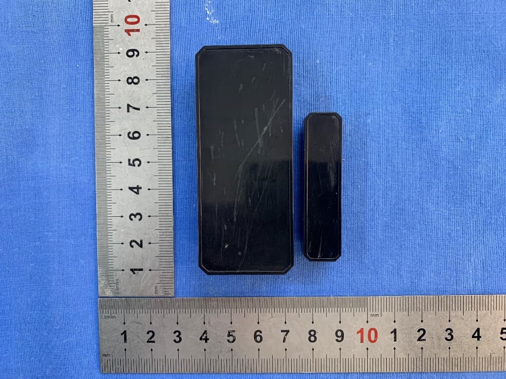
Click to zoom
Application Details
- Equipment Class
- DSC - Part 15 Security/Remote Control Transmitter
- Date of Grant
- May 25, 2021
- Application Purpose
- Original Equipment
- Date of Application
- May 25, 2021
- Equipment Note
- Door Sensor
- Frequency Range
- 433.92000000 - 433.92000000
- Country
- China
Documents & Files
Document Text
Text extracted from the exhibit documents filed with the FCC. Open a document above to read the original.
Users Manual
WIRELESS CHIME/PAGER FEATURES: Modern & Stylish design 5 levels of volume Easy installation IP55 Waterproof Approx. 1000ft/300mtrsoperation range (open air) 55 Ringtones Low power consumption SPECIFICATIONS: Working voltage of plug-in receiver 110-260V Battery in transmitter 12V/23A Alkaline battery Working temperature -30°C-70°C/-22F-158F PACKAGE LIST: Receiver User manual Transmitter (Optional) 12V/23A Battery Double sided adhesive tape PRODUCT DIAGRAM: RECEIVER TRANSMITTER 1: Call Button TRANSMITTER 2: Push Button of Doorbell TRANSMITTER 3: Door Sensor THE FIRST USE GUIDE: 1.Plug the receiver into a mains socket, and switch the socket on. 2. Press the transmitter push button and confirm that the transmitter indicator flashes, the doorbell receiver sounds "Ding-Ding" and the receiverindicator flashes. The doorbell is paired. The default ringtone is "Ding-Dong". Users can change the ringtone easily, just refer to the "CHANGINGTHE RINGIONE' steps. CHANGING THE RINGTONE / PAIRING: Step 1: Pres the (Forward) or(Backward) button on the receiver tochoose your favorite melody. Step 2: Press and hold down the (Volume) button on the receiver for 5seconds,until it makes a "Ding"sound and the receiver indicatorflashes (that means the doorbell entered into the Pairing Mode,thepairing mode will only last 8 seconds, then it will automatically exit). Step 3: Press the button on the transmitter quickly, it will makes a "Ding-Ding"sound and the receiver indicator flashes. Step 4: Press the button on the transmitter again to confirm whether the current ringtone is the one you have set, if yes, the pairing is completed. Remark: 1.This method is also suitable for adding/pairing additional Transmitters. 2. Ifpairing door sensor, let Gap between sensor part and magnet beyond10cm (to send out the signal) instead of Pressing the button. CLEARING THE SETTINGS: Press and hold down the Forward button on the receiverfor 5 seconds, until it makes a "Ding" sound and thereceiver indicator flashes, all the settings will be cleared,the doorbell will back to the factory default settings (it means that the ringtone you have set and the transmitters you have added/paired will be cleared). INSTALLATION: 1. Plug the receiver into a mains socket and switch the socket on. 2. Place the transmitter exactly where you intend to fix and, with the doorsclosed, confirm that the doorbell receiver still sounds when you press thetransmitter push button (If the doorbell receiver does not sound, this maybe due to metal within the fixing surface and you may need to repositionthe transmitter). 3. Fix the transmitter in place with (supplied) double sided adhesive tape. ADJUSTMENTS: 1. The volume of the doorbell may be adjusted to one offive levels. Pressthe Volume button on the receiver to increase the volume by one level,the receiver will sound to indicate the selected level.If the maximumlevel is already set, the doorbell will switch to the minimum level, whichis the Silent Mode. 2. The melody played by the doorbell may be set to any one of 55 differentselections. Press the Backward or Forward button to select the nextavailable melody, the receiver will sound to indicate the selected melody.To set the doorbell ringtone to the selected melody, please refer to the"CHANGING THE RINGTONE' steps. CHANGING THE BATTERY: 1. Insert the (supplied) Mini Screwdriver in the cover slot at the bottom ofthe transmitter and twist to release the transmitter from the cover. 2. Remove the exhausted battery and dispose of properly. 3. Insert the new battery into the battery compartment. Observe correct battery polarity (+ve and-ve), or the unit will not function and may bedamaged. 4. Refit the transmitter to the cover, with the push button at the bottom. PROBLEMS? If the doorbell does not sound, the following are possible causes: 1. The battery in the transmitter may be run down (the transmitter indicatorwill notflash). Replace the battery. 2. The battery may be inserted the wrong way round (polarity reversed), Insert the battery correctly, but be aware the reverse polarity may damagethe unit. 3. Ensure that the doorbell receiver is switched on at the mains. 4. Check that neither the transmitter nor the receiver are near to possiblesources of electrical interference, such as a power adaptor, or other wireless devices. 5. The range will be reduced by obstacles such as walls, although this willhave been checked during setup, Check that nothing, particularly ametalobject, has been placed between the transmitter and the receiver. Youmay need to reposition the doorbell. CAUTIONS: 1. Check that yourmains supply is correct for the doorbell receiver. 2. The receiver is for indoor use only. Do not use outside or allow to becomewet. 3.There are no user-serviceable parts. Do not attempt to repair either thetransmitter or the receiver by yourself. FCC Statement: Any Changes or modifications not expressly approved by the party responsible for compliance could void the user’s authority to operate the equipment. This device complies with part 15 of the FCC Rules. Operation is subject to the following two conditions: (1) This device may not cause harmful interference, and (2) This device must accept any interference received, including interference that may cause undesired operation. RF warning for Portable device: The device has been evaluated to meet general RF exposure requirement. The device can be used in portable exposure condition without restriction. ISED RSS Warning: This device complies with Innovation, Science and Economic Development Canada licence-exempt RSS standard(s). Operation is subject to the following two conditions: (1) this device may not cause interference, and (2) this device must accept any interference, including interference that may cause undesired operation of the device. Le présent appareil est conforme aux CNR d'ISED applicables aux appareils radio exempts de licence. L'exploitation est autorisée aux deux conditions sui…
Text truncated - open the document above for the full version.
Cover Letter(s)
Company Name: QUANZHOU DAYTECH ELECTRONICS CO., LTD. Add: Hengdali Business Center, North Quanan Road, Jinjiang City,Quanzhou,Fujian,China Tel: 18876258636 Fax : 0595-28271589 E-mail: [email protected] DECLARATION Date: 2021-03-22 FEDERAL COMMUNICATIONS COMMISSION Authorization and Evaluation Division 7435 Oakland Mills Road Columbia, MD 21046 Dear Sir or Madam: We, QUANZHOU DAYTECH ELECTRONICS CO., LTD., hereby declare th at product name: Door Sensor (model name: DS10BL, DS10WH. FCC ID: 2AWYQDS10BL). These models are electrically identical with the PCB design, components and electromagnetic compatibility characteristics. And DS10BL has been tested b y BACL. The differences of them are as follows: Mo del name. Please contact me if there is need for any additional clarification or information. Best Regards, Signature: Typed or Printed Name: Sally Yu Title: Manager
Cover Letter(s)
FCC Confidential Authorization 2021-03-22 FEDERAL COMMUNICATIONS COMMISSIONS Authorization and Evaluation Division 7435 Oakland Mi lls Road Columbia, MD 21046 Su bject: Confidentiality Request regarding application for certification of FCC ID: 2AWYQDS10BL In accordance with Sections 0.4 57 and 0.459 of the Commission’s Rules, QUANZHOU DAYTECH ELECTRONICS CO., LTD. hereby requests long-term confidential treatment o f information accompanying this application as outlined below: Block Diagram Schematics Operation Description The above materials contain proprietary and confidential information not customarily released to the public. The public disclosure of these materials provides unjustified benefits to its competitors in the market. Sincerely, Company Name: QUANZHOU DAYTECH ELECTRONICS CO., LTD. Add: Hengdali Business Center, North Quanan Road, Jinjiang City,Quanzhou,Fujian,China Tel: 18876258636 Fax: 0595-28271589 E-mail: [email protected] Sincerely Yours, QA-FR-172-A Signature: Typed or Printed Name: Sally Yu Title: Manager
External Photos
EXHIBIT A - EUT EXTERNAL PHOTOGRAPHS 2 3
Internal Photos
EXHIBIT B - EUT INTERNAL PHOTOGRAPHS Antenna
Test Report
FCC PART 15.231 TEST REPORT For QUANZHOU DAYTECH ELECTRONICS CO., LTD. Hengdali Business Center, North Quanan Road, Jinjiang City,Quanzhou,Fujian,China FCC ID: 2AWYQDS10BL Report Type: Original Report Product Type: Door Sensor Project Engineer: Miller Xie Report Number: RXM210322057-00A Report Date: 2021-04-21 Reviewed By: Oscar Ye EMC Manager Prepared By: Bay Area Compliance Laboratories Corp. (Kunshan) No.248 Chenghu Road, Kunshan, Jiangsu province, China Tel: +86-0512-86175000 Fax: +86-0512-88934268 www.baclcorp.com.cn Bay Area Compliance Laboratories Corp. (Kunshan) Report No.: RXM210322057-00A FCC Part 15.231 Page 2 of 19 TABLE OF CONTENTS GENERAL INFORMATION ....................................................................................................................................... 3 PRODUCT DESCRIPTION FOR EQUIPMENT UNDER TEST (EUT) ..................................................................................... 3 OBJECTIVE ................................................................................................................................................................... 3 RELATED SUBMITTAL(S)/GRANT(S) ............................................................................................................................. 3 TEST METHODOLOGY .................................................................................................................................................. 3 MEASUREMENT UNCERTAINTY .................................................................................................................................... 4 TEST FACILITY ............................................................................................................................................................. 4 SYSTEM TEST CONFIGURATION .......................................................................................................................... 5 JUSTIFICATION ............................................................................................................................................................. 5 EUT EXERCISE SOFTWARE .......................................................................................................................................... 5 EQUIPMENT MODIFICATIONS ....................................................................................................................................... 5 SUPPORT EQUIPMENT LIST AND DETAILS .................................................................................................................... 5 EXTERNAL I/O CABLE .................................................................................................................................................. 5 BLOCK DIAGRAM OF TEST SETUP ................................................................................................................................ 6 SUMMARY OF TEST RESULTS ............................................................................................................................... 7 TEST EQUIPMENT LIST ........................................................................................................................................... 8 FCC§15.203 - ANTENNA REQUIREMENT .............................................................................................................. 9 APPLICABLE STANDARD .............................................................................................................................................. 9 ANTENNA CONNECTED CONSTRUCTION ...................................................................................................................... 9 FCC §15.205, §15.209, §15.231 (B) - RADIATED EMISSIONS ............................................................................. 10 APPLICABLE STANDARD ............................................................................................................................................ 10 EUT SETUP ................................................................................................................................................................ 11 EMI TEST RECEIVER SETUP ....................................................................................................................................... 12 TEST PROCEDURE ...................................................................................................................................................... 12 CORRECTED AMPLITUDE & MARGIN CALCULATION ................................................................................................. 12 TEST RESULTS SUMMARY .......................................................................................................................................... 12 TEST DATA ................................................................................................................................................................ 12 FCC §15.231(A) (1) - DEACTIVATION TESTING ................................................................................................. 15 APPLICABLE STANDARD ............................................................................................................................................ 15 TEST PROCEDURE ...................................................................................................................................................... 15 TEST DATA ................................................................................................................................................................ 15 FCC §15.231(C) - 20DB EMISSION BANDWIDTH TESTING ............................................................................. 17 APPLICABLE STANDARD ............................................................................................................................................ 17 TEST PROCEDURE ...............................................................…
Text truncated - open the document above for the full version.
Test Setup Photos
EXHIBIT C - TEST SETUP PHOTOGRAPHS Radiated Emissions (Below 1GHz) Radiated Emissions (Above 1GHz)
Contact Information
Applicant
Sally Yu
Test Firm
Bay Area Compliance Laboratories Corp. (Kunshan)Mr. John Chan
[email protected]+86 0512 86175000
Technical Specifications
| # | Rule Parts | Frequency Range | Power Output |
|---|---|---|---|
| 1 | 15.231 | 433.92 MHz - 433.92 MHz | - |
Other Applications from QUANZHOU DAYTECH ELECTRONICS CO., LTD.
2AWYQ-DS17BL
Jan 10, 2024Door Sensor
Equipment Class
DSC - Part 15 Security/Remote Control Transmitter
2AWYQCB03-WH
May 25, 2021Call Button
Equipment Class
DSC - Part 15 Security/Remote Control Transmitter
2AWYQCB01-WG
May 25, 2021Call Button
Equipment Class
DSC - Part 15 Security/Remote Control Transmitter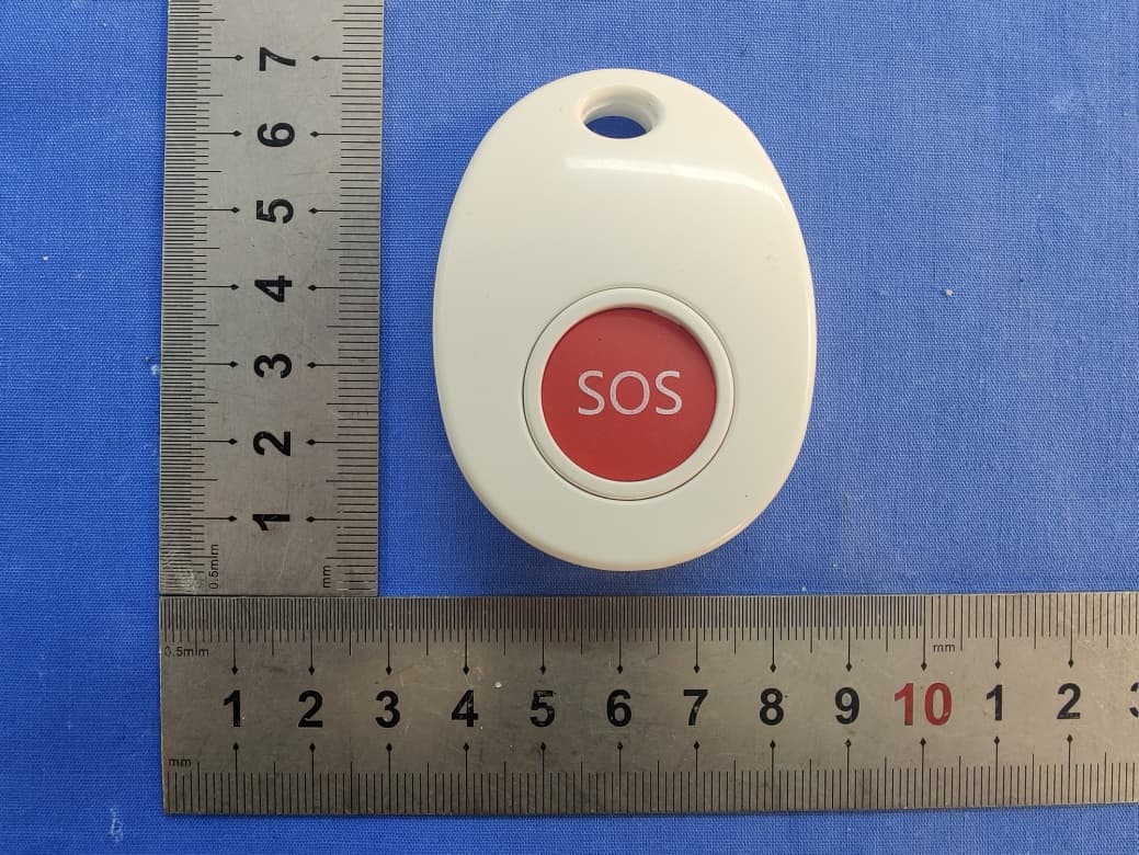
2AWYQBT003
May 25, 2021Call Button
Equipment Class
DSC - Part 15 Security/Remote Control Transmitter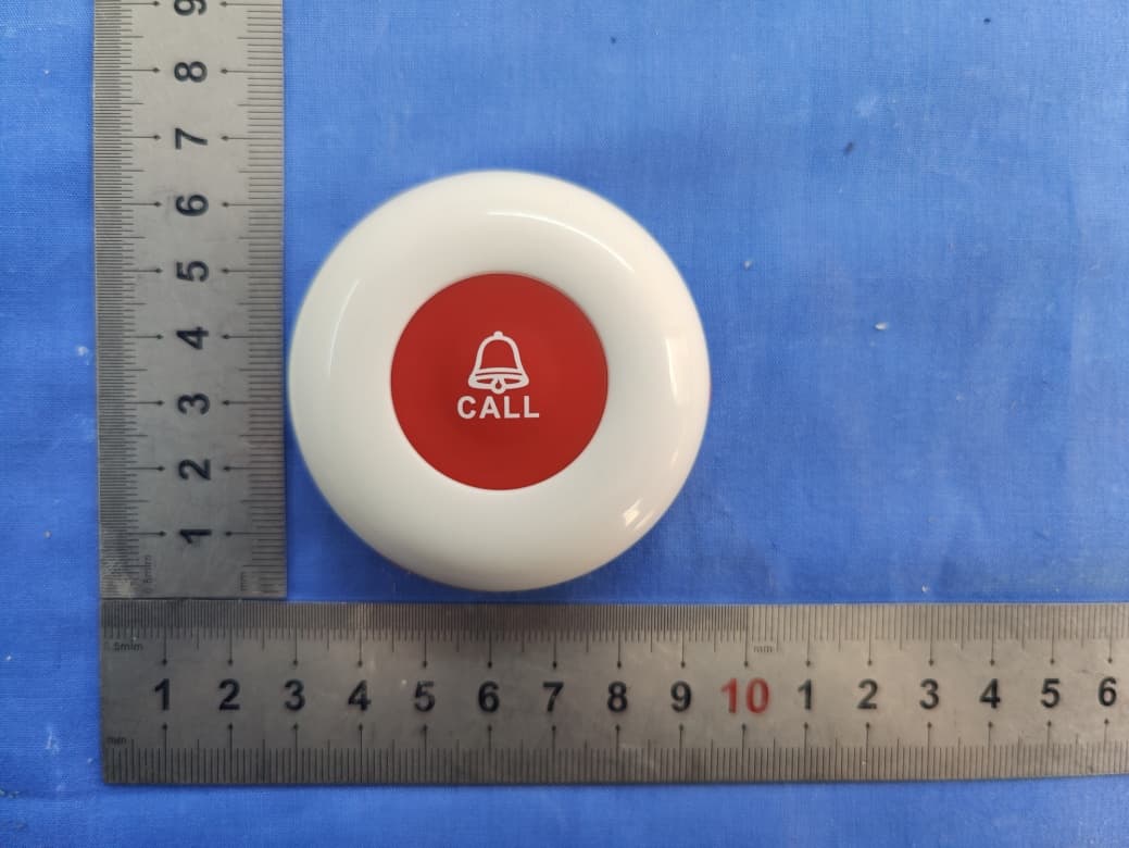
2AWYQE-01A-1
May 17, 2021Call Button
Equipment Class
DSC - Part 15 Security/Remote Control Transmitter