2AX37-PDQ1TEFUV Dryer
Ear Technology Corporation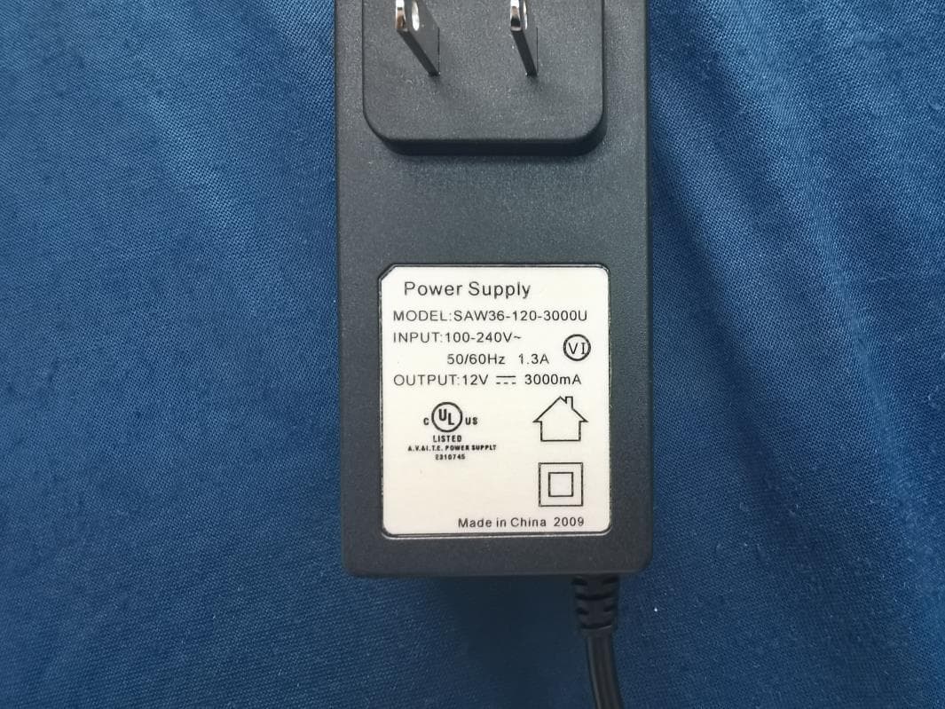
Click to zoom
Application Details
- Equipment Class
- DCD - Part 15 Low Power Transmitter Below 1705 kHz
- Date of Grant
- Dec 03, 2020
- Application Purpose
- Original Equipment
- Date of Application
- Dec 01, 2020
- Equipment Note
- UV Dryer
- Frequency Range
- 0.11000000 - 0.20500000
- Company
- Ear Technology Corporation
- Country
- United States
Documents & Files
Document Text
Text extracted from the exhibit documents filed with the FCC. Open a document above to read the original.
Users Manual
FREQUENTLY ASKED QUESTIONS HOW EFFECTIVE IS PHONEDRS AT DRYING MY PHONE? Our patented DryMax ® drying process used in the PHONEDRS removes about 20 drops of water per each drying cycle (that’s about 1/3 of a bottle cap). This dramatically reduces costly repairs (studies have shown that our drying process reduces the need for repair by almost 70%). PHONEDRS also improves the fidelity of the audio in your phone and other audio devices through the simple act of drying each night. An ounce of prevention is worth a pound of cure. DOES PHONEDRS REALLY KILL 99.99% OF THE GERMS ON MY PHONE? PHONEDRS was invented by a doctor with more than 50 years in practice. He has spent the last 25+ years inventing and selling products that combine our patented drying technology and the use of UV-C light to sanitize. As a result, he holds more than 200 patents worldwide. We have the experience and expertise to bring you the best disinfecting UV-C capabilities. PHONEDRS uses two high intensity 50mm linear (253.7nm) germicidal lamps rated at 70uW/cm2, with long-life expectancy. The UV-C lamps provide a LOG 4 kill rate of 99.99%. The wavelength of 253.7 nanometers is proven to inhibit colony formation in microorganisms. Results? Bacteria, germs, and viruses are gone, and your phone is cleaner than it’s ever been. You can Trust The Doctor to keep you and your phone healthy. WILL PHONEDRS DRY MY PHONE IF I DROPPED IT INTO WATER? While it is not specifically designed to dry electronics that have been submerged in water or left out in the rain, we know that it will dry electronics much more effectively than placing it into a bag of rice. We’d suggest you do the following if your phone or electronics become soaked. 1. Rigorously shake the phone so as much water will come out of the device as possible before starting the drying process. 2. Dry off any excess with a dry cloth. 3. Do NOT charge your phone before drying. – You will need to set the phone down on something to ensure it is at least 1” above the automatic charging pad like a stack of coasters or small rectangular box. – Ensure your PHONEDRS is on a stable surface so it won’t be knocked over and accidentally begin charging. 4. Run the PHONEDRS as normal multiple times as necessary. Each 6-hour cycle will remove about 20 drops of water so we recommend at least two or three 6-hour cycles before you try to power the phone on or off. 5. Most phones are water-resistant and will have a good chance of functioning normally depending on the extent of liquid damage it has. CAUTION: This device complies with Par t 15 of the FCC Rules / Innovation, Science and Economic Development Canada’s licence-exempt RSS(s). Operation is subject to the following two conditions: (1) this device may not cause harmful inter ference. (2) this device must accept any inter ference received, including interference that may cause undesired operation. L’émetteur/récepteur exempt de licence contenu dans le présent appareil est conforme aux CNR d’Innovation, Sciences et Développement économique Canada applicables aux appareils radio exempts de licence. L’exploitation est autorisée aux deux conditions suivantes: 1. L’appareil ne doit pas produire de brouillage; 2. L’appareil doit accepter tout brouillage radioélectrique subi, même si le brouillage est susceptible d’en compromettre le fonctionnement. Changes or modi cations not expressly approved by the par ty responsible for compliance could void the user’s authority to operate the equipment. This equipment has been tested and found to comply with the limits for a Class B digital device, pursuant to par t 15 of the FCC Rules. These limits are designed to provide reasonable protection against harmful interference in a residential installation. This equipment generates uses and can radiate radio frequency energy and, if not installed and used in accordance with the instructions, may cause harmful inter ference to radio communications. However, there is no guarantee that inter ference will not occur in a par ticular installation. If this equipment does cause harmful inter ference to radio or television reception, which can be determined by turning the equipment o and on, the user is encouraged to try to correct the inter ference by one or more of the following measures: — Reorient or relocate the receiving antenna. — Increase the separation between the equipment and receiver. — Connect the equipment into an outlet on a circuit di erent from that to which the receiver is connected. — Consult the dealer or an experienced radio/TV technician for help. QUICK START GUIDE PRODUCT SUPPORT 1-844-368-7905 WARRANTY INFORMATION www.PHONEDRS.com/warranty/ Model Number PDQ1TEF Q10 Includes Wireless Charging PHDRS Q10 QSG ENG 1120 Rev C 1-844-368-7905 | PHONEDRS.com | [email protected] FCC ID: 2AX37-PDQ1TEF IC: 26660-PDQ1TEF SECSEC SECSEC SECSEC SECSEC Plug the power plug into an electrical outlet. Place your phone on the tray. Touch for 1 SECOND for sanitizing (5 min.) and drying (6 hrs.). Touch and Hold for 3 SECONDS for sanitizing (5 min.) only. Plug the other end into the micro-USB port on PHONEDRS. Close the lid and touch the power button. The white LED will light to confirm your phone is charging. Close the lid. PHONEDRS will shut off automatically at the end of the cycle. Interrupt the cycle at any time by lifting the lid. The cycle will not restart once the lid is closed. Touch the power button for one second to restart the cycle. PHONEDRS has two USB ports in back for charging additional items (watch or other electronic devices). QUICK START Need assistance? 1-844-368-7905 | [email protected] Remember to register your PHONEDRS www.PHONEDRS.com/warranty WHAT’S INCLUDED?
Cover Letter(s)
Product name: UV Dryer Type/Model: PDQ1TEF FCC ID 2AX37-PDQ1TEF (1) Power transfer frequency is less than 1 MHz. Answer: The power transfer frequency is 110kHz – 205kHz (2) Output power from each primary coil is less than or equal to 15 watts. Answer: The max output power from each primary coil is 10 watts. (3) The transfer system includes only single primary and secondary coils. This includes charging systems that may have multiple primary coils and clients that are able to detect and allow coupling only between individual pairs of coils. Answer: The product has only single primary and secondary coils (4) Client device is placed directly in contact with the transmitter. Answer: The client device is placed directly in contact with the transmitter. (5) Mobile exposure conditions only (portable exposure conditions are not covered by this exclusion). Answer: Mobile exposure condition is used. (6) The aggregate H-field strengths at 15 cm surrounding the device and 20 cm above the top surface from all simultaneous transmitting coils are demonstrated to be less than 50% of the MPE limit. Answer: The H-field strengths at 15 cm surrounding the device and 20 cm above the top surface from all simultaneous transmitting coils is less than 50% of the MPE limit.
External Photos
FCC ID: 2AX37-PDQ1TEF IC: 26660-PDQ1TEF Page 1 of 4 External Picture FCC ID: 2AX37-PDQ1TEF IC: 26660-PDQ1TEF Page 2 of 4 FCC ID: 2AX37-PDQ1TEF IC: 26660-PDQ1TEF Page 3 of 4 FCC ID: 2AX37-PDQ1TEF IC: 26660-PDQ1TEF Page 4 of 4
Internal Photos
FCC ID: 2AX37-PDQ1TEF IC: 26660-PDQ1TEF Page 1 of 5 Internal Picture FCC ID: 2AX37-PDQ1TEF IC: 26660-PDQ1TEF Page 2 of 5 FCC ID: 2AX37-PDQ1TEF IC: 26660-PDQ1TEF Page 3 of 5 FCC ID: 2AX37-PDQ1TEF IC: 26660-PDQ1TEF Page 4 of 5 FCC ID: 2AX37-PDQ1TEF IC: 26660-PDQ1TEF Page 5 of 5
RF Exposure Info
Ear Technology Corporation MPE ASSESSMENT REPORT Report Type: FCC MPE assessment report Model: PDQ1TEF REPORT NUMBER: 201001453SHA-003 ISSUE DATE: Nov 25, 2020 DOCUMENT CONTROL NUMBER: TTRFFCCMPE-02_V1 © 2018 Intertek Intertek Testing Services Shanghai Building No.86, 1198 Qinzhou Road (North) Caohejing Development Zone Shanghai 200233, China Telephone: 86 21 6127 8200 www.intertek.com TEST REPORT This report is for the exclusive use of Intertek's Client and is provided pursuant to the agreement between Intertek and its Client. Intertek's responsibility and liability are limited to the terms and conditions of the agreement. Intertek assumes no liability to any party, other than to the Client in accordance with the agreement, for any loss, expense or damage occasioned by the use of this report. Only the Client is authorized to permit copying or distribution of this report and then only in its entirety. Any use of the Intertek name or one of its marks for the sale or advertisement of the tested material, product or service must first be approved in writing by Intertek. The observations and test results in this report are relevant only to the sample tested. This report by itself does not imply that the material, product, or service is or has ever been under an Intertek certification program. TTRFFCCMPE-02_V1© 2018 Intertek Page 2 of 10 Report no.: 201001453SHA-003 Applicant: Ear Technology Corporation 106E Watauga Ave Johnson City, TN 37601 USA Manufacturer: Xiamen Forsound Hearing Technology Co.,Ltd 4th Floor, Factory One, No. 158 Tianfeng Road, Jimei, Xiamen, Fujian, 361021 China Manufacturing site: Xiamen Forsound Hearing Technology Co.,Ltd 4th Floor, Factory One, No. 158 Tianfeng Road, Jimei, Xiamen, Fujian, 361021 China FCC ID: 2AX37-PDQ1TEF SUMMARY: The equipment complies with the requirements according to the following standard(s) or Specification: FCC PART 1 SECTION 1.1310 PREPARED BY: REVIEWED BY: Project Engineer Teddy Yin Reviewer Daniel Zhao Report No.: 201001453SHA-003 TEST REPORT TTRFFCCMPE-01_V1© 2018 Intertek Page 3 of 10 Revision History Report No. Version Description Issued Date 201001453SHA-003 Rev. 01 Initial issue of report Nov 25, 2020 Report No.: 201001453SHA-003 TEST REPORT TTRFFCCMPE-01_V1© 2018 Intertek Page 4 of 10 Measurement result summary TEST ITEM FCC REFERANCE TEST RESULT NOTE RF Exposure 1.1310 Pass - Notes: 1: NA =Not Applicable 2. Determination of the test conclusion is based on IEC Guide 115 in consideration of measurement uncertainty. 3: Additions, Deviations and Exclusions from Standards: None. Report No.: 201001453SHA-003 TEST REPORT TTRFFCCMPE-01_V1© 2018 Intertek Page 5 of 10 1 GENERAL INFORMATION 1.1 Description of Equipment Under Test (EUT) Product name: UV Dryer Type/Model: PDQ1TEF Description of EUT: EUT is a dryer with wireless charge function. The worst data is listed in the report. Rating: DC 12V, 3A Wireless charge output: DC 5V/1A, DC 9V/1.1A, USB output: DC 5V/2A Adaptor: SAW36-120-3000U Input: 100-240V~, 50/60Hz, 1.3A Output: DC 12V, 3000mA Category of EUT: Class B EUT type: Table top Floor standing Software Version: / Hardware Version: / Sample received date: Oct 29, 2020 Date of test: Oct 30~Nov 10, 2020 1.2 Technical Specification Frequency Range: 110kHz – 205kHz Report No.: 201001453SHA-003 TEST REPORT TTRFFCCMPE-01_V1© 2018 Intertek Page 6 of 10 1.3 Description of Test Facility Name: Intertek Testing Services Shanghai Address: Building 86, No. 1198 Qinzhou Road(North), Shanghai 200233, P.R. China Telephone: 86 21 61278200 Telefax: 86 21 54262353 The test facility is recognized, certified, or accredited by these organizations: CNAS Accreditation Lab Registration No. CNAS L0139 FCC Accredited Lab Designation Number: CN1175 IC Registration Lab CAB identifier.: CN0051 VCCI Registration Lab Registration No.: R-14243, G-10845, C-14723, T-12252 A2LA Accreditation Lab Certificate Number: 3309.02 Report No.: 201001453SHA-003 TEST REPORT TTRFFCCMPE-01_V1© 2018 Intertek Page 7 of 10 2 TEST SPECIFICATIONS 2.1 Standards or specification FCC PART 1 SECTION 1.1310 KDB 680106 D01 RF Exposure Wireless Charging App v03 2.2 Mode of operation during the test Within this test report, EUT was tested under all modes and tested under its rating voltage and frequency. Other voltage and frequency are specified if used. The worst data was listed in the report. 2.3 Test peripherals list Item No. Name Band and Model Description 1 Wireless load / 100% power level 2 Wireless load / 50% power level 3 Wireless load / 0% power level 2.4 Record of climatic conditions Test Item Temperature (°C) Relative Humidity (%) Pressure (kPa) RF Exposure 22C 55% RH 101 Report No.: 201001453SHA-003 TEST REPORT TTRFFCCMPE-01_V1© 2018 Intertek Page 8 of 10 2.5 Instrument list Used Equipment Manufacturer Type Internal no. Due date Exposure Level Tester Narda NBM-550 EC 6113 2020-11-20 Field sensor & Field meter Narda EF 0391 EC 6113 2020-12-26 Report No.: 201001453SHA-003 TEST REPORT TTRFFCCMPE-01_V1© 2018 Intertek Page 9 of 10 3 RF Exposure Assessment Test result: Pass 3.1 Assessment Limit 3.2 Assessment Configuration Report No.: 201001453SHA-003 TEST REPORT TTRFFCCMPE-01_V1© 2018 Intertek Page 10 of 10 3.3 Assessment Results Test result of Magnetic Field Strength: Test Position Test distance (cm) Test result (A/m) Limit (A/m) Result (Pass/Fail) A: Right 15 0.0011 1.63 *0.5 Pass B: Left 15 0.0013 1.63 *0.5 Pass C: Front 15 0.0008 1.63 *0.5 Pass D: Back 15 0.0011 1.63 *0.5 Pass E: Top 20 0.0018 1.63 *0.5 Pass Test result of Electric Field Strength: Test Position Test distance (cm) Test result (V/m) Limit (V/m) Result (Pass/Fail) A: Right 15 0.46 614 *0.5 Pass B: Left 15 0.47 614 *0.5 Pass C: Front 15 0.32 614 *0.5 Pass D: Back 15 0.49 614 *0.5 Pass E: Top 20 0.54 614 *0.5 Pass ******************************************* END ************************************
Test Report
Ear Technology Corporation RF TEST REPORT Report Type: FCC Part 15C RF report Model: PDQ1TEF REPORT NUMBER: 201001453SHA-001 ISSUE DATE: Nov 25, 2020 DOCUMENT CONTROL NUMBER: TTRFFCCPART15C_V1 © 2018 Intertek Intertek Testing Services Shanghai Building No.86, 1198 Qinzhou Road (North) Caohejing Development Zone Shanghai 200233, China Telephone: 86 21 6127 8200 www.intertek.com TEST REPORT This report is for the exclusive use of Intertek's Client and is provided pursuant to the agreement between Intertek and its Client. Intertek's responsibility and liability are limited to the terms and conditions of the agreement. Intertek assumes no liability to any party, other than to the Client in accordance with the agreement, for any loss, expense or damage occasioned by the use of this report. Only the Client is authorized to permit copying or distribution of this report and then only in its entirety. Any use of the Intertek name or one of its marks for the sale or advertisement of the tested material, product or service must first be approved in writing by Intertek. The observations and test results in this report are relevant only to the sample tested. This report by itself does not imply that the material, product, or service is or has ever been under an Intertek certification program. TTRFFCCPART15C_V1 © 2018 Intertek Page 2 of 19 Report no.: 201001453SHA-001 Applicant: Ear Technology Corporation 106E Watauga Ave Johnson City, TN 37601 USA Manufacturer: Xiamen Forsound Hearing Technology Co.,Ltd 4th Floor, Factory One, No. 158 Tianfeng Road, Jimei, Xiamen, Fujian, 361021 China Manufacturing site: Xiamen Forsound Hearing Technology Co.,Ltd 4th Floor, Factory One, No. 158 Tianfeng Road, Jimei, Xiamen, Fujian, 361021 China FCC ID: 2AX37-PDQ1TEF SUMMARY: The equipment complies with the requirements according to the following standard(s) or Specification: 47CFR Part 15 (2019): Radio Frequency Devices (Subpart C) ANSI C63.10 (2013): American National Standard of Procedures for Compliance Testing of Unlicensed Wireless Devices PREPARED BY: REVIEWED BY: Project Engineer Teddy Yin Reviewer Daniel Zhao Report No.: 201001453SHA-001 TEST REPORT TTRFFCCPART15C_V1 © 2018 Intertek Page 3 of 19 Content REVISION HISTORY................................................................................................................................................ 4 MEASUREMENT RESULT SUMMARY ..................................................................................................................... 5 1 GENERAL INFORMATION ............................................................................................................................. 6 1.1 DESCRIPTION OF EQUIPMENT UNDER TEST (EUT) ..................................................................................................... 6 1.2 TECHNICAL SPECIFICATION .................................................................................................................................... 6 1.3 DESCRIPTION OF TEST FACILITY .............................................................................................................................. 7 2 TEST SPECIFICATIONS ................................................................................................................................... 8 2.1 STANDARDS OR SPECIFICATION ............................................................................................................................... 8 2.2 MODE OF OPERATION DURING THE TEST ................................................................................................................... 8 2.3 TEST SOFTWARE LIST ............................................................................................................................................ 8 2.4 TEST PERIPHERALS LIST ......................................................................................................................................... 8 2.5 TEST ENVIRONMENT CONDITION: ............................................................................................................................ 8 2.6 INSTRUMENT LIST ................................................................................................................................................ 9 2.7 MEASUREMENT UNCERTAINTY ............................................................................................................................. 10 3 RADIATED EMISSIONS ............................................................................................................................... 11 3.1 LIMIT .............................................................................................................................................................. 11 3.2 MEASUREMENT PROCEDURE ............................................................................................................................... 11 3.3 TEST CONFIGURATION ........................................................................................................................................ 12 3.4 TEST RESULTS OF RADIATED EMISSIONS ................................................................................................................. 14 4 CONDUCTED EMISSIONS ........................................................................................................................... 16 4.1 LIMIT .............................................................................................................................................................. 16 4.2 TEST CONFIGURATION ........................................................................................................................................ 16 4.3 MEASUREMENT PROCEDURE ............................................................................................................................... 17 4.4 TEST RESULTS OF CONDUCTED EMISSIONS ...........................................................................…
Text truncated - open the document above for the full version.
Test Setup Photos
FCC ID: 2AX37-PDQ1TEF IC: 26660-PDQ1TEF Page 1 of 4 Test Setup FCC ID: 2AX37-PDQ1TEF IC: 26660-PDQ1TEF Page 2 of 4 1. Radiated Emission 30MHz- 1GHz Below 30MHz FCC ID: 2AX37-PDQ1TEF IC: 26660-PDQ1TEF Page 3 of 4 2. Conducted Emission FCC ID: 2AX37-PDQ1TEF IC: 26660-PDQ1TEF Page 4 of 4 3. RF Exposure for FCC 4. RF Exposure for IC
Contact Information
Applicant
Shawn Stahmer(Vice President)
Technical Contact
Intertek Testing Services ShanghaiTeddy Yin
[email protected]86 21 61215198
Building No.86 · Shanghai · China
Test Firm
Intertek Testing Services ShanghaiLeah Xu
[email protected]+86 21 61278200
Technical Specifications
| # | Rule Parts | Frequency Range | Power Output |
|---|---|---|---|
| 1 | 15C | 0.11 MHz - 0.205 MHz | - |