2AX4D-KTR140Neck Massager
Shenzhen Kentro Medical Electronics CO.,LTD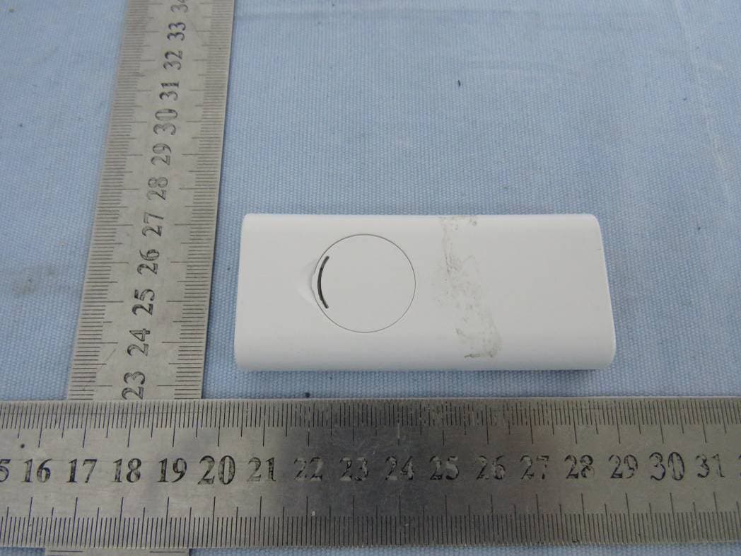
Click to zoom
Application Details
- Equipment Class
- DSC - Part 15 Security/Remote Control Transmitter
- Date of Grant
- Nov 19, 2020
- Application Purpose
- Original Equipment
- Date of Application
- Nov 19, 2020
- Equipment Note
- Neck Massager
- Frequency Range
- 433.92000000 - 433.92000000
- Country
- China
Documents & Files
Document Text
Text extracted from the exhibit documents filed with the FCC. Open a document above to read the original.
Users Manual
KTR-140 Shenzhen Kentro Medical Electronics Co.,Ltd 2nd Floor, No. 11, Shanzhuang Road, Xikeng Village, Yuanshan Street, Longgang District, Shenzhen City, Guangdon Province, China [Tel]: +86(755)33825998, [Fax]: +86(755)33825996 Product Introduction For people with cervical discomfort The scope of products The KTR-140 intelligent neck massager adopts a streamlined ring design that conforms to the physiological curvature of the human cervical spine. It uses low-frequency electrical pulses, magnetic effects, hot compresses, and circular traction to form a composite energy field for simultaneous multi-channel health care. Always maintain the correct physiological posture, providing a platform for the health of the cervical spine. Let you relax and enjoy the multifunctional system health care at home, so that you can get more value-added enjoyment! Product Features ■Designed according to ergonomics, beautiful and scientific, in line with the neck curve ■Low-frequency electric pulse, magnetic effect, hot compress and circular traction four-in-one synchronized health care form a composite energy field ■Hot compress, using three levels of low temperature, medium temperature and high temperature, you can choose according to your own needs and ambient temperature ■Using 3D smart fitting technology, you can easily adjust the electrodes according to your neck curve, making it more comfortable to use ■2 automatic combined massage modes, 4 manual massage modes, can be selected according to different needs, suitable for a wider range of people ■Built-in multiple healthy magnets ■Built-in rechargeable battery Electrode sheet (optional)USB charging cable How to Operate 1. Powersupply 1) USB power supply Insert the output end plug of the Micro USB cable into the lower hole (DC interface) of the massager, and then plug the input end pin of the Micro USB cable into the mobile phone charger or power bank (5V DC 1A or 2A) 1Built-in rechargeable battery power supplyWhen no external power supply is needed, the built-in rechargeable battery can supply power 2Remote control battery installation Install the button battery CR2032 in the battery compartment on the back of the remote control. The installation method is as shown in - as shown in the figure below. Use your fingers to unscrew the battery cover from the groove of the battery cover, and turn the button battery CR2032 front (positive +) upward , Put it in the battery compartment of the remote control, insert the positioning pin on the top of the battery cover first, and then press the battery cover tightly. 2Function operation 1Wet the cervical spine and the conductive sheet with a wet towel, and then put the massager close to the neck. If there is sweat on the cervical spine, it must be cleaned before use. 2Press the host key " " to enter the waiting state for signal reception, and the main unit's working indicator flashes (the main unit maintains the waiting signal reception state for 1 minute, and it will automatically shut down if it does not receive a remote control signal within 1 minute) Press the "" button on the remote control to turn on, the main unit will beep once, the screen backlight will light up, and the main unit work indicator will stay on, that is, the following settings are available: AAutomatic combination mode 1 massage Installation >>The use of remote control button battery 1The remote control uses a "CR2032" button battery, which can be used for about 3 months. (Use 30 minutes per day). 2When you press the button, the remote control L CD backlight brightness is significantly weakened or the remote control host is not sensitive, it means that the battery power is low, please replace with new batteries. 3When not using the product for a long time, please remove the battery. Otherwise, it may cause battery leakage and cause machine malfunction. 4Please do not use batteries other than the specified types. 5Do not install the wrong battery's positive and negative poles, with the positive pole facing up and the negative pole facing down. 6Do not use the battery in an environment above 45°C, otherwise it will affect the performance and life of the battery. 7Please dispose of the used battery in accordance with the city's relevant environmental protection regulations. B0th gear massage intensity C Moderate heat DTimed 15 minutes If you want to stop working, you can press and hold the remote control " " button for 2 seconds to shut down, or press the host " "Shut down directly. 3“ ”Key using In the off state, press the " " button on the host to enter the standby state, and press the " " button on the remote control to turn on; When it is on, short press the " " button on the host to turn off When powering on, press and hold the remote control "" button for 2 seconds to power off 4“ ”Key using Pulse mode switching button, you can select six pulse modes by pressing the remote control " " button, and the default setting is mode 1 (automatic combination 1 mode) when power on. The intensity is the first gear after each mode change. The six massage modes are Mode 1: Automatic combination 1 Mode 2: Automatic combination 2 Mode 3: Scratch Mode 4: Press Mode 5: Roll Mode 6: Beat The automatic combination mode 1 and 2 are manual modes after the automatic cycle, which automatically switches every minute. It is recommended to use the automatic combination mode. 5”"+" key using Pulse intensity enhancement key. Each time you turn on the machine, the intensity is set to 0 level. Press the "+" key once to increase the intensity by one level. There are a total of 0-16 levels of intensity. The massage should be at a self-acceptable intensity. It is recommended for the first use Start to adapt with weak gears. 6"-" key using Pulse intensity weakening key, each time you press the "-" key, the intensity will be weakened by one level, with a total of 0-16 levels. 7“ ”key using Press the " " button on the remote control to switch between three heating modes, name…
Text truncated - open the document above for the full version.
External Photos
Report No.: NTC2010229FV00 FCC ID: 2AX4D-KTR140 External photos Report No.: NTC2010229FV00 FCC ID: 2AX4D-KTR140 Report No.: NTC2010229FV00 FCC ID: 2AX4D-KTR140
Internal Photos
Report No.: NTC2010229FV00 FCC ID: 2AX4D-KTR140 Internal photos Report No.: NTC2010229FV00 FCC ID: 2AX4D-KTR140 Report No.: NTC2010229FV00 FCC ID: 2AX4D-KTR140
RF Exposure Info
Dongguan Nore Testing Center Co., Ltd. Report No.: NTC2010229FV00 FCC ID: 2AX4D-KTR140 RF EXPOSURE EVALUATION EUT Specification EUT Neck Massager Model Name KTR-140, KTR-132 Frequency band (Operating) WLAN: 2.412GHz ~ 2.462GHz WLAN: 5.18GHz ~ 5.32GHz / 5.50GHz ~ 5.70GHz WLAN: 5.745GHz ~ 5825GHz Others(433.92MHz) Device category Portable (<20cm separation) Mobile (>20cm separation) Others ___ Antenna diversity Single antenna Multiple antennas Tx diversity Rx diversity Tx/Rx diversity Max. output power 72.75 dBuV/m (-22.51dBm)( 0.0056mW) Antenna gain 0dBi Evaluation applied MPE Evaluation SAR Evaluation Dongguan Nore Testing Center Co., Ltd. Report No.: NTC2010229FV00 FCC ID: 2AX4D-KTR140 Standard Requirement Portable Device According to §15.247(i) and §1.1307b(1), systems operating under the provisions of this section shall be operated in a manner that ensures that the public is not exposed to radio frequency energy levels in excess of the Commission’s guidelines. See KDB 447498 D01 General RF Exposure Guidance v05, section 4.3.1. The 1-g and 10-g SAR test exclusion thresholds for 100 MHz to 6 GHz at test separation distances ≤ 50 mm are determined by: [(max. power of channel, including tune-up tolerance, mW)/(min. test separation distance, mm)] ·[√f(GHz)] ≤ 3.0 for 1-g SAR and ≤ 7.5 for 10-g extremity SAR, 16 where ·f(GHz) is the RF channel transmit frequency in GHz ·Power and distance are rounded to the nearest mW and mm before calculation17 ·The result is rounded to one decimal place for comparison The test exclusions are applicable only when the minimum test separation distance is ≤ 50 mm and for transmission frequencies between 100 MHz and 6 GHz. When the minimum test separation distance is < 5 mm, a distance of 5 mm is applied to determine SAR test exclusion. Measurement Result Channel Frequency (MHz) Max Output power (dBm) Max Output power (mW) Calculation Value (Note 1) Threshold Value 433.92 -22.51 0.0056 0.0007 3.0 EIRP=E-104.8+20logD=72.75-104.8+20log3=-22.51dBm Note 1: Calculation Value =[(max. power of channel, mW)/(min. test separation distance, mm)] ·[√f(GHz)]. Fox example: 0.24/5*√0.43392=0.0313 ≤ 3.0 According to KDB447498 D01 V05, threshold at which no SAR required is ≤3.0 for 1-g SAR, separation distance is 5mm, and no simultaneous SAR measurement is required. The SAR measurement is not necessary.
Test Report
Report No.: NTC2010229FV00 FCC ID: 2AX4D-KTR140 Page 2 of 31 Table of Contents 1. Summary of Test Result ...................................................................................................................................... 4 2. General Description of EUT ................................................................................................................................ 5 3. Test Channels and Modes Detail ........................................................................................................................ 7 4. Configuration of EUT ........................................................................................................................................... 7 5. Modification of EUT ............................................................................................................................................. 7 6. Description of Support Device............................................................................................................................. 7 7. Test Facility and Location ................................................................................................................................... 8 8. Applicable Standards and References ................................................................................................................ 9 9. Deviations and Abnormalities from Standard Conditions ................................................................................... 9 10. Test Conditions ................................................................................................................................................. 9 11. Measurement Uncertainty ............................................................................................................................... 10 12. Sample Calculations ....................................................................................................................................... 11 13. Duty Cycle ....................................................................................................................................................... 12 14. Test Items and Results ................................................................................................................................... 13 14.1 Conducted Emissions Measurement ............................................................................................................ 13 14.2 Radiated Spurious Emissions Measurement ................................................................................................ 15 14.3 20dB Occupied Bandwidth ............................................................................................................................ 26 14.4 Transmission Time ........................................................................................................................................ 28 14.5 Antenna Requirement ................................................................................................................................... 30 15. Test Equipment list .......................................................................................................................................... 31 Report No.: NTC2010229FV00 FCC ID: 2AX4D-KTR140 Page 3 of 31 Revision History Report Number Description Issued Date NTC2010229EV00 Initial Issue 2020-11-12 Report No.: NTC2010229FV00 FCC ID: 2AX4D-KTR140 Page 4 of 31 1. Summary of Test Result FCC Rules Description of Test Result Remarks §15.207 (a) AC Power Line Conducted EmissionN/A see note 2 --- §15.231(b) & 15.209 Radiated Spurious Emission PASS --- §15.231(c) 20 dB Occupied bandwidth PASS --- §15.231(a) Transmission time PASS --- §15.203 Antenna Requirement PASS --- Note: 1. The EUT has been tested as an independent unit. And continual transmitting in maximum power (New batteries were used during test) 2. AC Power Conducted Emission is not applicable due to the EUT only can be powered by battery. Report No.: NTC2010229FV00 FCC ID: 2AX4D-KTR140 Page 5 of 31 2. General Description of EUT Product Information Product Name: Neck Massager Main Model Name: KTR-140 Additional Model Name: KTR-132 Model Difference: Both of models have the same circuitry, electrical mechanical, PCB Layout and physical construction. The difference are model number and color due to marketing purpose. S/N: KTR1400506 Brand Name: KENTRO Hardware Version: V1.0 Software Version: V1.0 Rating: DC 3V(Button battery CR2032) Classification: Class B Typical arrangement: Table-top I/O Port: USB port, Output port Accessories Information Adapter: N/A Cable: USB Line: 1m unshielded Electrode Line: 1.19m unshielded Other: N/A Additional Information Note: According to the model difference, all tests were performed on model KTR-140. Remark: All the information above are provided by the manufacturer. More detailed feature of the EUT please refers to the user manual. Report No.: NTC2010229FV00 FCC ID: 2AX4D-KTR140 Page 6 of 31 Technical Specification (433MHz Transmitter) Declaring the Frequency: 433.92MHz Modulation Type: ASK Antenna Type: Integral antenna Antenna Gain: 0 dBi (Declared by manufacturer) Number of Channels: 1 Report No.: NTC2010229FV00 FCC ID: 2AX4D-KTR140 Page 7 of 31 3. Test Channels and Modes Detail Mode Test Frequency (MHz) Modulation Data Rate (Mbps) 1 TX 433.92MHz ASK ---- Note: TX mode means that the EUT was programmed to be in continuously transmitting mode. 4. Configuration of EUT TX Mode 5. Modification of EUT No modifications are made to the EUT during all test items. 6. Description of Support Device The EUT has been tested as an independent unit together with other necessary accessories or support units. The following support units or accessories were used to form a representative test configuration during the tests. No. Equipment Brand M/N S/N Cable Specification Remarks 1. --- --- --- --- --- --- EUT Report No.: NTC2010229FV00 FCC ID: 2AX4D…
Text truncated - open the document above for the full version.
Test Setup Photos
Report No.: NTC2010229FV00 FCC ID: 2AX4D-KTR140 Te s t P h o t o Radiated emission (Below 30MHz) Radiated emission (30-1000MHz) Report No.: NTC2010229FV00 FCC ID: 2AX4D-KTR140 Radiated emission (Above 1000MHz)
Contact Information
Applicant
zewu Zhang(Deputy General Manager)
Test Firm
Shenzhen Microtest Co., Ltd.Selby Liao
[email protected]0755-88850135-1193
Technical Specifications
| # | Rule Parts | Frequency Range | Power Output |
|---|---|---|---|
| 1 | 15.231 | 433.92 MHz - 433.92 MHz | - |