2AX59A040Welding Camera
Cavitar Ltd.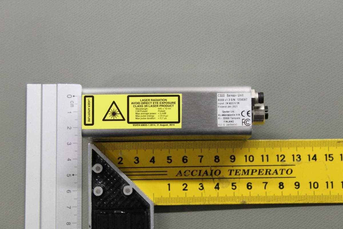
Click to zoom
Application Details
- Equipment Class
- JAD - Part 15 Class A Digital Device
- Date of Grant
- Feb 18, 2021
- Application Purpose
- Original Equipment
- Date of Application
- Feb 18, 2021
- Equipment Note
- Welding Camera
- Company
- Cavitar Ltd.
- Country
- Finland
Documents & Files
Document Text
Text extracted from the exhibit documents filed with the FCC. Open a document above to read the original.
Users Manual
CAVITAR Welding Camera C300 Operating Manual ii Contents 1 INTRODUCTION ......................................................................................................................... 1 2 SAFETY INFORMATION .......................................................................................................... 2 3 PROPERTIES ............................................................................................................................... 5 4 INSTALLATION ........................................................................................................................ 11 4.1 SOFTWARE INSTALLATION ........................................................................................................ 11 4.2 HARDWARE INSTALLATION ....................................................................................................... 15 5 OPERATION .............................................................................................................................. 18 5.1 BEFORE OPERATION .................................................................................................................. 18 5.2 CAVITAR CAPTURE SOFTWARE .............................................................................................. 18 5.2.1 Registration .................................................................................................................... 19 5.2.2 Opening the camera ........................................................................................................ 21 5.2.3 Overview of CAVITAR Capture ...................................................................................... 22 5.2.4 Camera settings .............................................................................................................. 24 5.2.5 Image adjustment ............................................................................................................ 25 5.2.6 Guidelines ....................................................................................................................... 27 5.2.7 Calibration...................................................................................................................... 29 5.2.8 Recording settings .......................................................................................................... 33 5.2.9 Recording images ........................................................................................................... 34 5.2.10 Viewing and saving recorded images ........................................................................ 34 5.2.11 Snapshot ..................................................................................................................... 36 5.3 STARTING AND STOPPING LASER ILLUMINATION ....................................................................... 37 5.4 AFTER OPERATION .................................................................................................................... 37 5.5 TROUBLESHOOTING .................................................................................................................. 38 6 MAINTENANCE AND SERVICE INFORMATION ............................................................. 39 7 SUPPORT AND END OF LIFE ................................................................................................ 40 8 LIMITED WARRANTY ............................................................................................................ 41 Cavitar Welding Camera, model C300 (Cavitar product code A040) Operating Manual, Revision 1.1.0 © 2021 Cavitar Ltd. All rights reserved. All unauthorized copying strictly prohibited. Cavitar ® is a registered trademark of Cavitar Ltd. 1 1 Introduction Thank you for choosing Cavitar Welding Camera model C300 (later: Welding Camera)! Welding Camera is a Finnish quality product developed and manufactured by Cavitar Ltd. We hope that you will be satisfied with your product. Welding Camera is a highly compact and easy-to-use visualization system for the online monitoring of various welding processes, including MIG, MAG and TIG processes. Welding Camera contains several unique features in order to enable highest possible image quality. These features include, among other things, extremely powerful spectral filtering combined with wavelength-stabilized laser output. Standard Welding Camera has a fixed working distance (specified upon order), but adjustable working distance (adjustment range 150 mm ... 300 mm) is available as an option. The laser source of the system doesn’t require any control by the operator. Therefore, from the operation point of view, the system doesn’t differ from a normal machine vision camera system. Welding Camera is a class 3R laser product with a nominal ocular hazard distance (NOHD) of 3 meters. Please read this operating manual carefully before using Welding Camera. Chapter 2 contains important safety information for the safe operation of Welding Camera. Chapter 3 describes the properties of Welding Camera and Chapter 4 deals with the installation of the system. Chapter 5 describes the operation of Welding Camera. Chapters 6 to 8 cover issues related to maintenance, service, support and warranty. The actual appearance of software or components may vary. The symbols below are applied throughout this operating manual: NOTE! indicates useful tips for easier operation CAUTION! indicates potential risk of serious damage to the device WARNING! indicates potential risk of serious injury to the user 2 2 Safety information PLEASE CAREFULLY READ AND UNDERSTAND THE FOLLOWING SAFETY INSTRUCTIONS BEFORE USING WELDING CAMERA. IT IS OF UTMOST IMPORTANCE TO STRICTLY OBEY THESE INSTRUCTIONS. OTHERWISE SERIOUS DAMAGE TO THE USER OR TO THE DEVICE MAY OCCUR. ONLY A PERSON, WHO HAS CAREFULLY READ AND UNDERSTOOD ALL SAFETY INSTRUCTIONS BELOW AND THE REST OF THIS OPERATING MANUAL, IS QUALIFIED FOR USING WELDING CAMERA. CAVITAR LTD. IS NOT LIABLE F…
Text truncated - open the document above for the full version.
External Photos
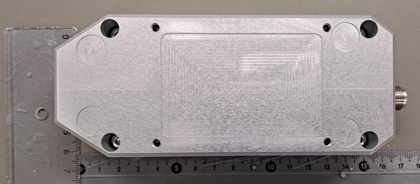
CAVITAR Welding Camera C300 External Photographs Cavitar Welding Camera, model C300 (Cavitar product code A040) External Photographs, Revision 1.0.1 © 2020 Cavitar Ltd. All rights reserved. All unauthorized copying strictly prohibited. Cavitar ® is a registered trademark of Cavitar Ltd. 1 1. Top 2. Side 2 3. Bottom 4. Side 3 5. Front and back 6. Label and label location
ID Label/Location Info
CAVITAR Welding Camera C300 External Photographs Cavitar Welding Camera, model C300 (Cavitar product code A040) External Photographs, Revision 1.0.1 © 2020 Cavitar Ltd. All rights reserved. All unauthorized copying strictly prohibited. Cavitar ® is a registered trademark of Cavitar Ltd. 1 1. Top 2. Side 2 3. Bottom 4. Side 3 5. Front and back 6. Label and label location
Test Report
Reference number: 300089-1 Page 1 of 14 These test results are valid for the tested unit only. This report shall not be reproduced, except in full, without a written permission of SGS Fimko. Test Report Electromagnetic Compatibility (EMC) TESTS ACCORDING TO FCC PART 15 B AND INDUSTRY CANADA REQUIREMENTS Equipment Under Test: Welding Camera Model: C300 Type: - Manufacturer: Cavitar Ltd. Kuokkamaantie 4 A FI-33800 Tampere Finland Customer: Cavitar Ltd. Kuokkamaantie 4 A FI-33800 Tampere Finland FCC Rule Part: FCC CFR 47 Part 15 Subpart B (2019), Class A IC Rule Part: ICES-003 Issue 6 (update 2019), Class A Date: 18 November 2020 Date: 18 November 2020 Issued by: Checked by: Henri Mäki Rauno Repo Testing Engineer Senior EMC/RF Specialist Reference number: 300089-1 Page 2 of 14 Table of Contents TABLE OF CONTENTS TABLE OF CONTENTS ................................................................................................................................. 2 GENERAL REMARKS ................................................................................................................................... 3 Disclaimer ................................................................................................................................................. 3 RELEASE HISTORY...................................................................................................................................... 4 PRODUCT DESCRIPTION ............................................................................................................................ 5 Equipment Under Test (EUT) .................................................................................................................... 5 General description ................................................................................................................................... 5 Samples and modifications........................................................................................................................ 5 Ports and cables ....................................................................................................................................... 6 Peripherals ............................................................................................................................................... 6 TEST CONDITIONS ...................................................................................................................................... 7 EUT Test Conditions During EMC-Testing ................................................................................................. 7 Operation modes ...................................................................................................................................... 7 Emission Measurement Uncertainty .......................................................................................................... 8 SUMMARY OF TESTING .............................................................................................................................. 8 EMISSION TEST RESULTS .......................................................................................................................... 9 Conducted Emissions In The Frequency Range 150 kHz – 30 MHz........................................................... 9 Radiated Emissions In The Frequency Range 30 – 5000 MHz................................................................... 11 TEST EQUIPMENT ....................................................................................................................................... 14 Conducted Emissions ............................................................................................................................... 14 Radiated Emissions .................................................................................................................................. 14 Reference number: 300089-1 Page 3 of 14 General remarks GENERAL REMARKS Disclaimer This document is issued by the Company subject to its General Conditions of Service printed overleaf, avail- able on request or accessible at http://www.sgs.com/en/Terms-and-Conditions.aspx and, for electronic for- mat documents, subject to Terms and Conditions for Electronic Documents at http://www.sgs.com/en/Terms- and-Conditions/Terms-e-Document.aspx Attention is drawn to the limitation of liability, indemnification and jurisdiction issues defined therein. Any holder of this document is advised that information contained hereon reflects the Company’s findings at the time of its intervention only and within the limits of Client’s instructions, if any. The Company’s sole respon- sibility is to its Client and this document does not exonerate parties to a transaction from exercising all their rights and obligations under the transaction documents. This document cannot be reproduced except in full, without prior written approval of the Company. Any unauthorized alteration, forgery or falsification of the content or appearance of this document is unlawful and offenders may be prosecuted to the fullest extent of the law. Unless otherwise stated the results shown in this test report refer only to the sample(s) tested and such sample(s) are retained for 30 days only. Reference number: 300089-1 Page 4 of 14 Release History RELEASE HISTORY Version Changes Issued 1.0 Initial release 18 November 2020 Reference number: 300089-1 Page 5 of 14 Product Description PRODUCT DESCRIPTION Equipment Under Test (EUT) EUT information General Product Description Welding Camera Trademark Cavitar Welding Camera Model C300 Type - Serial number 5640345 Power input port type Sensor unit: DC, Power supply: AC Rated voltage Sensor unit: 24 V DC , Power supply: 100 – 240 V AC Rated current Sensor unit: 0.5 A, Power supply: 0.22 – 0.55 A Rated frequency Sensor unit: DC, Power supply: 47 – 63 Hz Rated power Sensor unit: 12 W, Power supply: 25 W EUT Highest operation freq. 600 MHz Hardware …
Text truncated - open the document above for the full version.
Test Setup Photos
TEST SETUP PHOTOGRAPHS Page 1 of 3 Project number: 300089-1 SGS Fimko Ltd. Takomotie 8, FI-00380 Helsinki Finland t +358 9 6963 361 f +358 9 692 5474 www.sgs.fi Member of SGS Group (Société Générale de Surveillance) Photograph 1: The EUT Photograph 2: The EUT (heat sinks detached) TEST SETUP PHOTOGRAPHS Page 2 of 3 Project number: 300089-1 SGS Fimko Ltd. Takomotie 8, FI-00380 Helsinki Finland t +358 9 6963 361 f +358 9 692 5474 www.sgs.fi Member of SGS Group (Société Générale de Surveillance) Photograph 3: Type label of the EUT Photograph 4: Radiated emissions (30-1000 MHz) test setup TEST SETUP PHOTOGRAPHS Page 3 of 3 Project number: 300089-1 SGS Fimko Ltd. Takomotie 8, FI-00380 Helsinki Finland t +358 9 6963 361 f +358 9 692 5474 www.sgs.fi Member of SGS Group (Société Générale de Surveillance) Photograph 5: Radiated emissions (1-5 GHz) test setup Photograph 6: Conducted emissions (150 kHz – 30 MHz) test setup
Contact Information
Applicant
Erkki Lassila(VP, R&D)
Technical Contact
Non-Technical Contact
Cavitar LtdTommi Rantanen
[email protected]35834479330
Test Firm
SGS Fimko OyJanne Nyman
Technical Specifications
| # | Rule Parts | Frequency Range | Power Output |
|---|---|---|---|
| 1 | 15B | - | - |
Other Applications from Cavitar Ltd.
2AX59A026
Jan 17, 2022CAVILUX OEM Sapotech System
Equipment Class
JAD - Part 15 Class A Digital Device