2AX5D-X1PROMicrosoft Pen
Shenzhen Uogic Tech co., Ltd.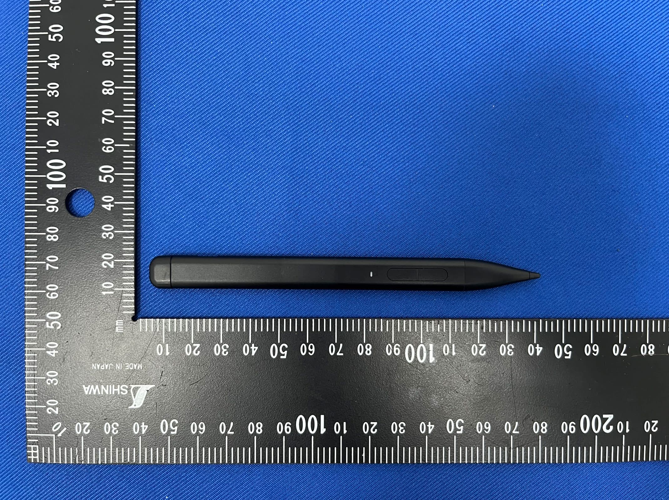
Click to zoom
Application Details
- Equipment Class
- DTS - Digital Transmission System
- Date of Grant
- Oct 11, 2023
- Application Purpose
- Original Equipment
- Date of Application
- Oct 11, 2023
- Equipment Note
- Microsoft Pen
- Frequency Range
- 2402.00000000 - 2480.00000000
- Country
- China
Documents & Files
Document Text
Text extracted from the exhibit documents filed with the FCC. Open a document above to read the original.
Users Manual
X1 Pro Stylus User Manual Windows ink button Type-C charging port LED indicator light Eraser / Power on Right mouse Nib ● Click the power button to start the device. ● The onboard power management program automatically shuts down after ten minutes of inactivity. How to use? ● The demonstration is under Windows 10 system. ● Before connecting to the device, it is necessary to ensure that the device supports Bluetooth connectivity. ● Press and hold the top function key for 3 seconds, and the indicator light will flash blue. Enter Bluetooth adaptation status. ● Click [Start Menu] - [Settings] - [Bluetooth and Other Devices] - [Add Bluetooth or Other Devices] - [Bluetooth] to enter the Windows Bluetooth search status, and click to match [Uogic Pen]. Click on [Start Menu] - [Settings] - [Pen and Windows Ink] to set the top Windows ink function button. ● At most three operation commands can be set. They are single click, double click, and triple click. How to using Windows ink workspace settings ● Compatible with all touchscreens that support Mpp 2.0 or MPP 1.51 protocols. Compatible ● This product is guaranteed for 12 months. Warranty terms 1、Do not use this product on other surfaces other than the screen to avoid damage to the screen caused by the wear of the pen nibs. 3、The nib will wear out due to long-term use and friction, please replace the nib regularly to avoid damage to the screen. 4、Please keep the pen out of the reach of children or pets to avoid other injuries caused by accidental swallowing by children or pets. 6、Do not use any solution or liquid to clean this product, so as to avoid the solution or liquid flowing into the product during cleaning, which will cause the product to get wet or damage the internal components. 7、Some screen stickers may affect the writing experience. 8、Radio frequency radiation from electronic Note ●Red light flashing (Charging prompt) ●The red light flashing once (Low voltage protection) ●Red light will turn green after flashing(Low battery) ●Blue light flashing (Bluetooth matching status) Indicator light This device complies with Part 15 of the FCC Rules. Operation is subject to the following two conditions: (1) This device may not cause harmful interference, and (2) This device must accept any interference received, including interference that may cause undesired operation. FCC STATEMENT : The device has been evaluated to meet general RF exposure requirement. The device can be used in portable exposure condition without restriction. RF warning statement: Changes or modifications not expressly approved by the party responsible for compliance could void the user's authority to operate the equipment. NOTE: This equipment has been tested and found to comply with the limits for a Class B digital device, pursuant to Part 15 of the FCC Rules. These limits are designed to provide reasonable protection against harmful interference in a residential installation. This equipment generates uses and can radiate radio frequency energy and, if not installed and used in accordance with the instructions, may cause harmful interference to radio communications. However, there is no guarantee that interference will not occur in a particular installation. If this equipment does cause harmful interference to radio or television reception, which can be determined by turning the equipment off and on, the user is encour- aged to try to correct the interference by one or more of the following measures: Reorient or relocate the receiving antenna. ● Increase the separation between the equipment and receiver. ● Connect the equipment into an outlet on a circuit different from that to which the receiver is connected. ● Consult the dealer or an experienced radio/TV technician for help. Warning: Specifications Tip: If there is ink leakage when replacing the nib, please recharge the device before use. Name Model Protocol version Pressure Battery Capacity Use time Charging time Stylus X1 Pro MPP 2.0 4096 70 mAh 60 hours hour Accessory Capacitive pen * 1,CtC adapter * 1, Nib * 1, Input voltage5V 200mA
Attestation Statements
- Shenzhen Uogic Tech co., Ltd. - The information provided in this letter is based on the referenced rule parts of Title 47 of the CFR as well as KDB 986446 D01. An expiration date for this letter does not exist. In case the U.S. agent changes, the grantee is obligated to notify the FCC within 30 days via the granting TCB. Federal Communications Commission Authorization and Evaluation Division Equipment Authorization Branch 7435 Oakland Mills Road Columbia, MD 21046 10/12/2023 U.S. Agent Designation [Shenzhen Uogic Tech co., Ltd.] acknowledges their consent for the following contact located in the United States to act as their agent for service of process for the equipment for which authorization is sought (FCC ID: [2AX5D-X1PRO]): Name and company of U.S. agent: Stone Trading Limited Physical U.S. address of agent: 6547 N Academy Blvd #2266,Colorado Springs,CO 80918,United States FRN of U.S. agent: 0033401936 Email address of U.S. agent: [email protected] [Stone Trading Limited] acknowledges their obligation to accept service of process on behalf of [Shenzhen Uogic Tech co., Ltd.]. [Shenzhen Uogic Tech co., Ltd.] with the FRN [0030170724] accepts its obligation to maintain an agent for service of process in the United States for no less than one year after either the grantee has permanentl y terminated all marketing and importation of the applicable equipment within the U.S., or the conclusion of any Commission-related administrative or judicial proceeding involving the equipment, whichever is later. By signing this form, we confirm th e above and that we are aware of the application requirements listed under § 2.911(d)(7). Sincerely, Signature [Name] Kang Lin Li [Title] CEO [Company] Shenzhen Uogic Tech co., Ltd. [Name of U.S. agent] Dongmei Fang [Title of U.S. agent] Manager [Company of U.S. agent] Stone Trading Limited 48_[mo del] US_Agent_2.911(d)(7) - U, V04
Attestation Statements
Shenzhen Uogic Tech co., Ltd. The information provided in this letter is based on the referenced rule parts of Title 47 of the CFR as well as KDB 986446 D01. Federal Communications Commission Authorization and Evaluation Division Equipment Authorization Branch 7435 Oakland Mills Road Columbia, MD 21046 10/12/2023 To whom it may concern: We, [Shenzhen Uogic Tech co., Ltd.], hereby certify that the equipment for which authorization is sought (FCC ID: [2AX5D-X1PRO]) is not “covered” equipment prohibited from receiving an equipment authorization pursuant to § 2.903 of the FCC rules. We also certify that, as of the date of the fi lin g of the application, we are not identified on the Covered List (https://www.fcc.gov/supplychain/coveredlist ) as an entity producing “covered” equipment. By signing this form, we confirm the above and that we are aware of the application requirements listed under § 2.911(b) and (d)(5) and (6). Sincerely, Signature [Name] Kang Lin Li [Title] CEO [Company] Shenzhen Uogic Tech co., Ltd. 62_[model] CoveredEqu_2.911(d)(5)(i) and (ii) - U, V02
External Photos
EXTERNAL PHOTOGRAPH (Model No.: X1 pro) ---------------- End ----------------
ID Label/Location Info
Label Location On EUT Label Product Name: Microsoft Pen Model Number: X1 pro FCC ID: 2AX5D-X1PRO
Internal Photos
INTERNAL PHOTOGRAPH (Model No.: X1 pro) ---------------- End ---------------- Ceramic Antenna
RF Exposure Info
RF EXPOSURE EVALUATION FCC ID: 2AX5D-X1PRO According to FCC 1.1310: The criteria listed in the following table shall be used to evaluate the environment impact of human exposure to radio frequency(RF) Radiation as specified in §1.1307(b): Routine SAR evaluation refers to that specifically required by §2.1093, using measurements or computer simulation. When routine SAR evaluation is not required, portable transmitters with output power greater than the applicable low threshold require SAR evaluation to qualify for TCB approval. Channel (MHz) Maximum output power (dBm) Tune up tolerance (dBm) Max Tune Up Power (dBm) Distance (mm) Calculation results Limit Operating Mode 2402 2.75 2.75±1 3.75 5 0.735 3 BLE 2440 2.87 2.87±1 3.87 5 0.762 3 2480 2.44 2.44±1 3.44 5 0.695 3 Test Results: PASS.
Test Report
Project No.: ZKT-230912L7090E Page 1 of 43 FCC TEST REPORT FCC ID: 2AX5D-X1PRO Report Number. ................................ : ZKT-230912L7090E Date of Test ........................................ Aug. 22, 2023 – Oct. 10, 2023 Date of issue .................................... : Oct. 12, 2023 Total number of pages ...................... 43 Test Result ..................................... : PASS Testing Laboratory. ........................ : Shenzhen ZKT Technology Co., Ltd. Address .......................................... : 1 / F, No. 101, Building B, No. 6, Tangwei Community Industrial Avenue, Fuhai Street, Bao'an District, Shenzhen, China Applicant's name ......................... : Shenzhen Uogic Tech co., Ltd. Address .......................................... : 403A, Kelente R&D Building, No. 1 Ganliwu Road, Gankeng Community, Jihua Street, Longgang District, Shenzhen City, China Manufacturer's name ................... : Shenzhen Uogic Tech co., Ltd. Address .......................................... : 403A, Kelente R&D Building, No. 1 Ganliwu Road, Gankeng Community, Jihua Street, Longgang District, Shenzhen City, China Test specification: Standard .......................................... : FCC CFR Title 47 Part 15 Subpart C Section 15.247 ANSI C63.10:2013 Test procedure ................................. : / Non-standard test method ............. : N/A Test Report Form No. .................... : TRF-EL-111_V0 Test Report Form(s) Originator .... : ZKT Testing Master TRF .................................... : Dated: 2020-01-06 This device described above has been tested by ZKT, and the test results show that the equipment under test (EUT) is in compliance with the FCC requirements. And it is applicable only to the tested sample identified in the report. This report shall not be reproduced except in full, without the written approval of ZKT, this document may be altered or revised by ZKT, personal only, and shall be noted in the revision of the document. Product name ................................. : Microsoft Pen Trademark ...................................... : N/A Model/Type reference......................: X1 pro Ratings ............................................. : Input: DC 5V, 200mA Battery: DC 3.7V, 70mAh Project No.: ZKT-230912L7090E Page 2 of 43 Testing procedure and testing location: Testing Laboratory ................................... : Shenzhen ZKT Technology Co., Ltd. Address ...................................................... : 1/F, No. 101, Building B, No. 6, Tangwei Community Industrial Avenue, Fuhai Street, Bao'an District, Shenzhen, China Jim Liu Tested by (name + signature) .................... : Tom Zou Reviewer (name + signature) ..................... : Lake Xie Approved (name + signature) .................... : Project No.: ZKT-230912L7090E Page 3 of 43 Table of Contents Page 1.VERSION 5 2. SUMMARY OF TEST RESULTS 6 2.1 TEST FACILITY 7 2.2 MEASUREMENT UNCERTAINTY 7 3. GENERAL INFORMATION 8 3.1 GENERAL DESCRIPTION OF EUT 8 3.2 DESCRIPTION OF TEST MODES 9 3.3 BLOCK DIGRAM SHOWING THE CONFIGURATION OF SYSTEM TESTED 9 3.4 DESCRIPTION OF SUPPORT UNITS(CONDUCTED MODE) 9 3.5 EQUIPMENTS LIST FOR ALL TEST ITEMS 10 4. EMC EMISSION TEST 12 4.1 CONDUCTED EMISSION MEASUREMENT 12 4.1.1 POWER LINE CONDUCTED EMISSION LIMITS 12 4.1.2 TEST PROCEDURE 12 4.1.3 DEVIATION FROM TEST STANDARD 12 4.1.4 TEST SETUP 13 4.1.5 EUT OPERATING CONDITIONS 13 4.2 RADIATED EMISSION MEASUREMENT 16 4.2.1 RADIATED EMISSION LIMITS 16 4.2.2 TEST PROCEDURE 17 4.2.3 DEVIATION FROM TEST STANDARD 17 4.2.4 TEST SETUP 17 4.2.5 EUT OPERATING CONDITIONS 18 5.RADIATED BAND EMISSION MEASUREMENT 24 5.1 TEST REQUIREMENT: 24 5.2 TEST PROCEDURE 24 5.3 DEVIATION FROM TEST STANDARD 24 5.4 TEST SETUP 25 5.5 EUT OPERATING CONDITIONS 25 5.6 TEST RESULT 26 6.POWER SPECTRAL DENSITY TEST 27 6.1 APPLIED PROCEDURES / LIMIT 27 6.2 TEST PROCEDURE 27 6.3 DEVIATION FROM STANDARD 27 6.4 TEST SETUP 27 6.5 EUT OPERATION CONDITIONS 27 Project No.: ZKT-230912L7090E Page 4 of 43 Table of Contents Page 6.6 TEST RESULT 28 7. CHANNEL BANDWIDTH 30 7.1 APPLIED PROCEDURES / LIMIT 30 7.2 TEST PROCEDURE 30 7.3 DEVIATION FROM STANDARD 30 7.4 TEST SETUP 30 7.5 EUT OPERATION CONDITIONS 30 7.6 TEST RESULT 31 8.PEAK OUTPUT POWER TEST 33 8.1 APPLIED PROCEDURES / LIMIT 33 8.2 TEST PROCEDURE 33 8.3 DEVIATION FROM STANDARD 33 8.4 TEST SETUP 33 8.5 EUT OPERATION CONDITIONS 33 8.6 TEST RESULT 34 9. CONDUCTED BAND EDGE AND SPURIOUS EMISSION 36 9.1 APPLICABLE STANDARD 36 9.2 TEST PROCEDURE 36 9.3 DEVIATION FROM STANDARD 36 9.4 TEST SETUP 36 9.5 EUT OPERATION CONDITIONS 36 10.ANTENNA REQUIREMENT 42 11. TEST SETUP PHOTO 43 12. EUT CONSTRUCTIONAL DETAILS 43 Project No.: ZKT-230912L7090E Page 5 of 43 1.VERSION Report No. Version Description Approved ZKT-230912L7090E Rev.01 Initial issue of report Oct. 12, 2023 Project No.: ZKT-230912L7090E Page 6 of 43 2. SUMMARY OF TEST RESULTS Test procedures according to the technical standards: FCC Part15 (15.247) , Subpart C Standard Section Test Item Judgment Remark FCC part 15.203/15.247 (c) Antenna requirement PASS FCC part 15.207 AC Power Line Conducted Emission PASS FCC part 15.247 (b)(3) Conducted Peak Output Power PASS FCC part 15.247 (a)(2) Channel Bandwidth& 99% OCB PASS FCC part 15.247 (e) Power Spectral Density PASS FCC part 15.247(d) Band Edge PASS FCC part 15.205/15.209 Spurious Emission PASS NOTE: (1)“N/A” denotes test is not applicable in this Test Report Project No.: ZKT-230912L7090E Page 7 of 43 2.1 TEST FACILITY Shenzhen ZKT Technology Co., Ltd. Add. : 1/F, No. 101, Building B, No. 6, Tangwei Community Industrial Avenue, Fuhai Street, Bao'an District, Shenzhen, China FCC Test Firm Registration Number: 692225 Designation Number: CN1299 IC Registered No.: 27033 2.2 MEASUREMENT UNCERTAINTY The reported uncertainty of measurement y ± U,where expended uncertainty U is based on a standard uncertainty multiplied by a coverage factor of k=2,providing a level of confidence of approximately 95 %。…
Text truncated - open the document above for the full version.
Test Report
AT3216-E2R4HAAT/LF REV:3 PAGE:1/8 ACX Advanced Ceramic X Features Monolithic SMD with small, low-profile and light-weight type. Wide bandwidth Applications Bluetooth/Wireless LAN/Home RF ISM band 2.4GHz applications Specifications Part Number Operating Frequency (MHz) Peak Gain (YZ-total) Average Gain (YZ-total) VSWR Impedance AT3216 -E2R4HAA_ 2400 ~ 2500 1.0 dBi typ. -3.0 dBi typ.4.0 max. 50 Q’ty/Reel (pcs) : 3,000pcs Operating Temperature Range : -40 ~ +85 o C Storage Temperature Range : +5 ~ +35 o C, Humidity 45~75%RH Storage Period : 12 months max. Power Capacity : 2W max. Part Number Type AT : Antenna Dimensions ( L × W ) 3.2× 1.6 mm Material Code E Initial center frequency 2R4=2400MHz Specification Code HAA Packaging T: Tape & Reel B: Bulk Soldering =lead-containing /LF=lead-free AT3216 Series (Preliminary) Multilayer Chip Antenna AT 3216 - E 2R4 HAA AT3216-E2R4HAAT/LF REV:3 PAGE:2/8 ACX Advanced Ceramic X Terminal Configuration No. Terminal Name No. Terminal Name Feeding Point GND Dimensions and Recommended PC Board Pattern Mark L W T a Dimensions 3.2±0.2 1.6±0.2 1.2+ 0.1/-0.2 0.5±0.3 With Matching Circuits - Unit in mm *Line width should be designed to match 50 characteristic impedance, depending on PCB material and thickness. Typical Electrical Characteristics (T=25 o C) * Unit : mm L W a T 0.5 0.4 0.5 7.5 1.0 4.5 3.1 2.1 0.5 0.4 0.5 0.7 0.8 2.2 0.8 1.0 1.6 1.0 1.1 0.8 0.8 0Ohm 1.2nH AT3216-E2R4HAA Ground Via 0Ohm Feeding line AT3216-E2R4HAAT/LF REV:3 PAGE:3/8 ACX Advanced Ceramic X Test Board Return Loss-with matching circuits 2.22.42.62.82.03.0 -30 -20 -10 -40 0 freq, GHz dB(S(1,1)) m1 m2 m3 m1 freq= dB(S(1,1))=-8.50 8 2.400GHz m2 freq= dB(S(1,1))=-7.70 2 2.500GHz m3 freq= dB(S(1,1))=-35.19 4 2.450GHz Via Groun d Feeding Line Antenna No Ground 100m m 40mm 10mm 4.5mm AT3216-E2R4HAAT/LF REV:3 PAGE:4/8 ACX Advanced Ceramic X Radiation Patterns XZ-V/XZ-H 180 o 270 o 0 o 90 o X Z Y XZ-cut scanning direction XZ cut @ 2.45GHz Vertical Horizontal XY-V/XY-H 180 o 270 o 0 o 90 o X Z Y XY-cut scanning direction XY cut @ 2.45GHz Vertical Horizontal YZ cut @ 2.45GHz Vertical Horizontal YZ-V/YZ-H 180 o 270 o 0 o 90 o X Z Y YZ-cut scanning direction AT3216-E2R4HAAT/LF REV:3 PAGE:5/8 ACX Advanced Ceramic X Taping Specifications Tape & Reel Dimensions (Unit: mm) vs. Quantity (pcs) Type A A’ B C D E F T Quantity/per reelTape material AT3216 4.0± 0.1 4.0± 0.05 1.88± 0.1 3.5± 0.1 2.0± 0.05 3.5± 0.05 8.00± 0.1 1.27± 0.1 3,000pcs Plastic (Embossed) Reel Dimensions (Unit: mm) Leader and Trailer Tape Type W2 W3 W4 W5 AT3216 178±1 60±1 1.4±0.2 17±0.5 F A’ D E 1.75 ± 0.1 AB EMBOSS TA P E T C ∣ W2 13.5±0.5 2.3 ±0.5 Label Label: Customer’s Name, ACX P/N, Q’ty, Date, ACX Corp. W4 W5 W3 Trailer End Trailer (160 mm min.) Leader End Empty Compartments with Cover Tape (500 mm min.) AT3216-E2R4HAAT/LF REV:3 PAGE:6/8 ACX Advanced Ceramic X Peel-off Force Peel-off force should be in the range of 0.1 – 0.6 N at a peel-off speed of 300±10 mm/min . Storage Conditions (1) Temperature: 15 ~35°C, relative humidity (RH): 45~75%. (2) Non-corrosive environment Notes The contents of this data sheet are subject to change without notice. Please confirm the specifications and delivery conditions when placing your order. Peeling Direction Top Cover Tape Carrier Tape <10 0 AT3216-E2R4HAAT/LF REV:3 PAGE:7/8 ACX Advanced Ceramic X Mechanical & Environmental Characteristics Item Requirements Procedure Solderability 1. No apparent damage 2. More than 95% of the terminal electrode shall be covered with new solder 1. Preheat: 120 5 o C 2. Solder: 245 5 o C for 5 1 sec Soldering strength (Termination Adhesion) 1. 1kg minimum 1. Solder specimen onto test jig. 2. Apply push force at 0.5mm/s until electrode pads are peeled off or ceramic are broken. Pushing force is applied to longitude direction Deflection (Substrate Bending) 1. No apparent damage 1. Solder specimen onto test jig (FR4, 0.8mm) using the recommend soldering profile. 2. Apply a bending force of 2mm deflection ` Heat/Humidity Resistance 1. No apparent damage 2. Fulfill the electrical specification after test 1. Temperature: 85 2 o C 2. Humidity: 90% ~ 95% RH 3. Duration: 1000±48hrs 4. Recovery: 1-2hrs Thermal shock (Temperature Cycle) 1. No apparent damage 2. Fulfill the electrical specification after test 1. One cycle/step 1:125 ± 5C for 30 min step 2:- 40 ± 5C for 30 min 2. No of cycles:100 3. Recovery:1-2 hrs Low Temperature Resistance 1. No apparent damage 2. Fulfill the electrical specification after test 1. Temperature: -40 o 5 o C 2. Duration: 500 ±24hrs 3. Recovery: 1-2hrs 90mm Pressure Rod R230 AT3216-E2R4HAAT/LF REV:3 PAGE:8/8 ACX Advanced Ceramic X Soldering Conditions Typical Soldering Profile for Lead-free Process Reflow Soldering : Notes The contents of this data sheet are subject to change without notice. Please confirm the specifications and delivery conditions when placing your order. Temperature ( o C) Pre-heating 60-180s Time (s.) 20s max. 260 o C 150-200 o C 217 o C 60-150s. Advanced Ceramic X Corp. 16 Tzu Chiang Road, Hsinchu Industrial District Hsinchu Hsien 303, Taiwan TEL:886-3-5987008 FAX:886-3-5987001 E-mail: [email protected] http://www.acxc.com.tw
Test Setup Photos
EUT TEST PHOTO
Contact Information
Applicant
Kang Lin LI(CEO)
Test Firm
Shenzhen ZKT Technology Co., Ltd.Lake Xie
[email protected]0086-13620010775
Technical Specifications
| # | Rule Parts | Frequency Range | Power Output |
|---|---|---|---|
| 1 | 15C | 2.40 GHz - 2.48 GHz | 1.90 mW |
Other Applications from Shenzhen Uogic Tech co., Ltd.
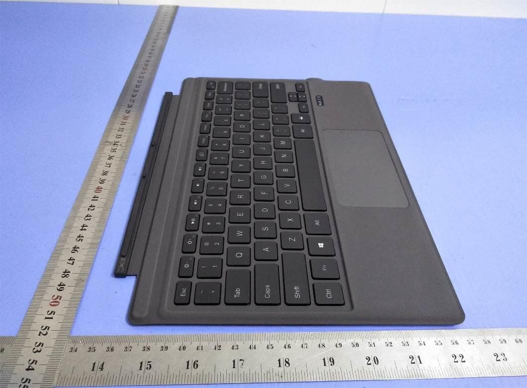
2AX5D-UK01
May 19, 2021Uogic keyboard
Equipment Class
DTS - Digital Transmission System