2AXEL-C5SWireless Bluetooth Headset
Shenzhen Calion Power Co., Ltd.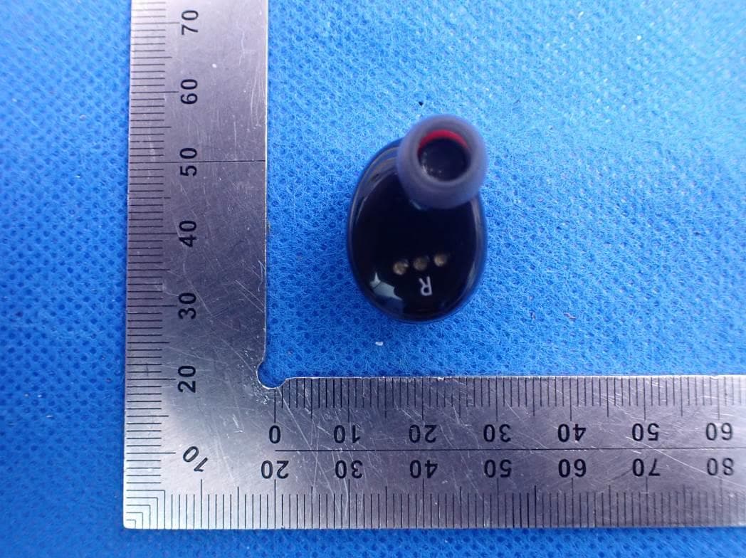
Click to zoom
Application Details
- Equipment Class
- DSS - Part 15 Spread Spectrum Transmitter
- Date of Grant
- Dec 30, 2020
- Application Purpose
- Original Equipment
- Date of Application
- Dec 30, 2020
- Equipment Note
- Wireless Bluetooth Headset
- Frequency Range
- 2402.00000000 - 2480.00000000
- Country
- China
Documents & Files
Document Text
Text extracted from the exhibit documents filed with the FCC. Open a document above to read the original.
Users Manual
English C5S V02 Thank you for purchasing the C5S wireless earbuds ! The C5S has newest technology and exceptional audio quality to reach for all touch control function. The C5S focus on improving and enhancing user experience by providing a comfortable and ergonomic in-ear design. For wearing freely that the earbuds adopt soft in-ear design to fit user perfectly. With the portable charging, you can enjoy charging anytime and anywhere. For the best user experience, please read this manual carefully before use of the C5S earbuds. Safety Rules 1. For safety, please comply with the rules mentioned in this manual 2. Keep device away from sharp edges, uneven surfaces, metal objects, and knock out. 3.Do not open, dismantle or attempt to repair the earbuds.Doing so may cause accidental fire, electronic board failure, or damage to the earbuds. All warranty will be cancel. 4. Do not wipe or clean the earbuds with oils or any volatile liquids. 5. Do not use the earbuds in places where potential personal safety is atrisk or in danger. brief introduction 1 — C5S Bluetooth headset 1 pair — Charging Cable 1 — Medium silicone ear cap 1 pair — Small silicone ear cap 1 pair Product Information Packing details — Instruction manual 1 serving — Charging storage box 1 — Hanging rope 1 — Packing box 1 set ① charging storage box ② cavity ③ battery display ④ charging display ⑤ microphone ⑥ silicone ear cap ⑦ silicone plug ⑧ headphone work indicator 2 1. Headphone wearing method R/L is printed on the earphone case, please wear it in the correct direction, the sound quality will be better! LED downward 2. Connect to Phone: A.Take out the earbuds from charging case and remove the PET insulator. Put the earbuds back in the charging case to activate. The earbuds will power on automatically once you take them out of the case B.Put the L and R earbuds into your ears. The L and R earbud will content each other and pairing. Next, the prompts of voice “connected ”will be heard C.Open Bluetooth on your phone. When the two earbuds has pair successfully, the prompts of voice"Left channel, Right channel"will be heard. On the device list, connect to the"Touch Two C5S and then the voice “second device connected” will be heard D.How to use the single ear: The L/R Earbud can use alone. When you first use this earphone and you want to use the L/R earphone alone. You must double-click the L/R ear touch surface. Then you can find the “Touch Two C5S" in the Bluetooth device connection list. If you have connected your phone with the two earphones. When you use L/R earphone alone. Put one of the L/R earphone back into the charging box. Operation Guide 3 3.Touch Functions: Previous: Double click on the right ear touch surface. Volume reduction: Long press of right ear touch surface. Next: Double click on the left ear touch surface Volume increase: Long press of left ear touch surface. 4 To turn off the earbuds: In standby mode, press and hold the touch area for 5S to turn off the earbuds. (Note:The earbuds can be used individual To turn off a single earphone which does not affect to use another earphone) (Note: left and right can be operated separately) Activate voice assistant: Standby mode, Continuous click Touch panel three times Call function: click once on the touch panel to answer Or hang up the phone. Reject the call: double click on the touch panel Play or pause music: Click once in the touch panel ATTENTION: PLEASE REMOVETHE PROTECTIVE COVER ON THE EARBUDS BEFORE OPERATION. PLEASE KEEP AWAY FROM RADIO INTERFERENCE AND AVOID NOISY ENVIRONMENTS WHENUSING EABUDS PLEASE REPLAY THE HIGHT QUALITY FORMAT OF MUSIC OR LOCAL MUSIC OF THE DEVICE 4. Charging Case A. Put the earbuds into the case exactly, the battery box wil automatically charge the earphones until they are full. B. The charging box has a smart switch function.Place the earbuds in the charging box and cover the case which is charged . When the charging box is opened, the charging will be turned off automatically. The earphone will start uppair and connect back to the mobile phone when you pick up the earbuds from the open box.Then you can listen to music and enjoy the intelligence of this product. C. USB outlet supports 5V/1.5A output, which can provide emergency charging for mobile phones and other electronic products ATTENTION: REMOVE THE INSULATION COVER BEFORE INITIAL USE. RECHARGE THE CHARGING CASE IF NOT USED FOR OVER 90 DAYS. ONLY USE GOOD OUALITY WIRELESS CHARGING TRANSMITTER AND CHARGING CABLE. THE EARBUD LED LIGHT WILL TURN BLUE WHEN IT IS FULLY CHARGED 5. Single Earbud Mode: The L/R Earbud can used alone to connect to your Phone. On your phone, enter the Bluetooth device connection list and remove the"Touch Two C5S "from the list. Redo the steps for Connect to Phone"but with only the L/R earbud. 5 1. Earbud parameters: Bluetooth Version: 5.0 Operation Voltage: 3.2V-4 2V Impedance: 32Ω Speakersensitivity: 105db Speaker Bandwidth: 20-20 KHZ Microphone Sensitivity: -42+-2db Earbud frequency: 2. 4-2.48GHZ Compatible : A2DP/HFP/HSP/AVRCPEarbud working range: 10M Single eartalk time: 6hrs Music play : 4-5hrs Single earbud standby time: 80 hrs 2. Charging case Parameters: Large capacity battery DC Charging Volta ge: DC5V DC charge Current: 1A DC output Current: Maximum 1. 5A Troubleshooting Guide Product Parameter Put the phone closer to the main earb ud or keep ifrom the oute r inter ference signal The volume is too high or the envi ronment is to o noisy Can talk, but red indicator illuminates malfunction Caused by environmental interference or Sound source equipment is far away the reason Solution Unable to start Silent after matching Charging without prompt Headset Automatic shut-down Headphones have echo The call has a noise The other party’s voice is small Low battery Match operation is incorrect The battery is low, Bright red indicator The headphones are not put well Low battery Charge the headset Rematch Clear the headset immediately Check if the headphones are i…
Text truncated - open the document above for the full version.
Cover Letter(s)
Shenzhen Calion Power Co., Ltd. Dec.30, 2020 Office of Engineering Technology Federal Communications Commission 7435 Oakland Mills Road Columbia, MD 21046 USA Subject: Explanation of differences between product types FCC ID : 2AXEL-C5S Model Number: C5S, C5P, C7, C8, C3, C5, A1 To Whom It May Concern: We, The Shenzhen Calion Power Co., Ltd. hereby declare that the model : C5P, C7, C8, C3, C5, A1 is identical with the model : C5S, except the model name and plastic appearance. Except for the different above, no other modification is performed. Sincerely, Signature: Shenzhen Calion Power Co., Ltd. Contact person: Guanghuo Guo
Cover Letter(s)
Shenzhen Calion Power Co., Ltd. Agent Authorization Company: Shenzhen Calion Power Co., Ltd. Address: Room 1202,12th Floor, Huitong Building,No.10Longgang Road, Pingnan Community, Longgang Street, Longgan District, Shenzhen,China Product Name: Wireless Bluetooth Headset Model Number(s): C5S, C5P, C7, C8, C3, C5, A1 Product Description: Wireless Bluetooth Headset We authorize MiCOM Labs Inc., 575 Boulder Court, Pleasanton, California 94566, USA, to act on our behalf on all matters concerning the certification of above named equipment. We declare that MiCOM Labs Inc. is allowed to forward all information related to the approval and certification of equipment to the regulatory agencies as required and to discuss any issues concerning the approval application. Any and all acts carried out by MiCOM Labs on our behalf shall have the same effect as acts of our own. Signature: Date: 2020-12-30 Name: Guanghuo Guo Company: Shenzhen Calion Power Co., Ltd.
External Photos
External Photos THE MAIN TEST MODEL IS C5S WHOLE VIEW OF EUT-1 WHOLE VIEW OF EUT-2 TOP VIEW OF EUT BOTTOM VIEW OF EUT FRONT VIEW OF EUT BACK VIEW OF EUT LEFT VIEW OF EUT RIGHT VIEW OF EUT Left VIEW OF EUT(PORT) Right VIEW OF EUT(PORT) THE SERIES MODEL IS C5P TOP VIEW OF EUT BOTTOM VIEW OF EUT FRONT VIEW OF EUT BACK VIEW OF EUT LEFT VIEW OF EUT RIGHT VIEW OF EUT Left VIEW OF EUT(PORT) Right VIEW OF EUT(PORT) THE SERIES MODEL IS C7 TOP VIEW OF EUT BOTTOM VIEW OF EUT FRONT VIEW OF EUT BACK VIEW OF EUT LEFT VIEW OF EUT RIGHT VIEW OF EUT Left VIEW OF EUT(PORT) Right VIEW OF EUT(PORT) THE SERIES MODEL IS C8 TOP VIEW OF EUT BOTTOM VIEW OF EUT FRONT VIEW OF EUT BACK VIEW OF EUT LEFT VIEW OF EUT RIGHT VIEW OF EUT Left VIEW OF EUT(PORT) Right VIEW OF EUT(PORT)
External Photos
THE SERIES MODEL IS C3 TOP VIEW OF EUT BOTTOM VIEW OF EUT FRONT VIEW OF EUT BACK VIEW OF EUT LEFT VIEW OF EUT RIGHT VIEW OF EUT Left VIEW OF EUT(PORT) Right VIEW OF EUT(PORT) THE SERIES MODEL IS C5 TOP VIEW OF EUT BOTTOM VIEW OF EUT FRONT VIEW OF EUT BACK VIEW OF EUT LEFT VIEW OF EUT RIGHT VIEW OF EUT Left VIEW OF EUT(PORT) Right VIEW OF EUT(PORT) THE SERIES MODEL IS A1 TOP VIEW OF EUT BOTTOM VIEW OF EUT FRONT VIEW OF EUT BACK VIEW OF EUT LEFT VIEW OF EUT RIGHT VIEW OF EUT Left VIEW OF EUT(PORT) Right VIEW OF EUT(PORT)
ID Label/Location Info
FCC ID Label Location The product does not have enough space to place the label, and FCC ID label is reflected in the user manual and package, as below:
Internal Photos
Internal Photos THE MAIN TEST MODEL IS C5S Left OPEN VIEW OF EUT VIEW OF BATTERY INTERNAL VIEW OF EUT-1 INTERNAL VIEW OF EUT-2 BT Antenna INTERNAL VIEW OF EUT-3 INTERNAL VIEW OF EUT-4 Right OPEN VIEW OF EUT VIEW OF BATTERY INTERNAL VIEW OF EUT-1 INTERNAL VIEW OF EUT-2 BT Antenna INTERNAL VIEW OF EUT-3 INTERNAL VIEW OF EUT-4 THE SERIES MODEL IS C5P Left OPEN VIEW OF EUT VIEW OF BATTERY INTERNAL VIEW OF EUT-1 INTERNAL VIEW OF EUT-2 BT Antenna INTERNAL VIEW OF EUT-3 INTERNAL VIEW OF EUT-4 Right OPEN VIEW OF EUT VIEW OF BATTERY INTERNAL VIEW OF EUT-1 INTERNAL VIEW OF EUT-2 BT Antenna INTERNAL VIEW OF EUT-3 INTERNAL VIEW OF EUT-4 THE SERIES MODEL IS C7 Left OPEN VIEW OF EUT VIEW OF BATTERY INTERNAL VIEW OF EUT-1 INTERNAL VIEW OF EUT-2 BT Antenna INTERNAL VIEW OF EUT-3 INTERNAL VIEW OF EUT-4 Right OPEN VIEW OF EUT VIEW OF BATTERY INTERNAL VIEW OF EUT-1 INTERNAL VIEW OF EUT-2 BT Antenna INTERNAL VIEW OF EUT-3 INTERNAL VIEW OF EUT-4 THE SERIES MODEL IS C8 Left OPEN VIEW OF EUT VIEW OF BATTERY INTERNAL VIEW OF EUT-1 INTERNAL VIEW OF EUT-2 BT Antenna INTERNAL VIEW OF EUT-3 INTERNAL VIEW OF EUT-4 Right OPEN VIEW OF EUT VIEW OF BATTERY INTERNAL VIEW OF EUT-1 INTERNAL VIEW OF EUT-2 BT Antenna INTERNAL VIEW OF EUT-3 INTERNAL VIEW OF EUT-4
Internal Photos
THE SERIES MODEL IS C3 Left OPEN VIEW OF EUT VIEW OF BATTERY INTERNAL VIEW OF EUT-1 INTERNAL VIEW OF EUT-2 BT Antenna INTERNAL VIEW OF EUT-3 INTERNAL VIEW OF EUT-4 Right OPEN VIEW OF EUT VIEW OF BATTERY INTERNAL VIEW OF EUT-1 INTERNAL VIEW OF EUT-2 BT Antenna INTERNAL VIEW OF EUT-3 INTERNAL VIEW OF EUT-4 THE SERIES MODEL IS C5 Left OPEN VIEW OF EUT VIEW OF BATTERY INTERNAL VIEW OF EUT-1 INTERNAL VIEW OF EUT-2 BT Antenna INTERNAL VIEW OF EUT-3 INTERNAL VIEW OF EUT-4 Right OPEN VIEW OF EUT VIEW OF BATTERY INTERNAL VIEW OF EUT-1 INTERNAL VIEW OF EUT-2 BT Antenna INTERNAL VIEW OF EUT-3 INTERNAL VIEW OF EUT-4 THE SERIES MODEL IS A1 Left OPEN VIEW OF EUT VIEW OF BATTERY INTERNAL VIEW OF EUT-1 INTERNAL VIEW OF EUT-2 BT Antenna INTERNAL VIEW OF EUT-3 INTERNAL VIEW OF EUT-4 Right OPEN VIEW OF EUT VIEW OF BATTERY INTERNAL VIEW OF EUT-1 INTERNAL VIEW OF EUT-2 BT Antenna INTERNAL VIEW OF EUT-3 INTERNAL VIEW OF EUT-4
RF Exposure Info
RF EXPOSURE EVALUATION 1. PRODUCT INFORMATION Product Description Wireless Bluetooth Headset Model Name C5S, C5P, C7, C8, C3, C5, A1 FCC ID 2AXEL-C5S 2. EVALUATION METHOD According to 447498 D01 General RF Exposure Guidance v05 The 1-g and 10-g SAR test exclusion thresholds for 100 MHz to 6 GHz at test separation distances ≤ 50 mm are determined by: [(max. power of channel, including tune-up tolerance, mW)/(min. test separation distance, mm)] ·[√f(GHz)] ≤ 3.0 for 1-g SAR and ≤ 7.5 for 10-g extremity SAR. Where f(GHz) is the RF channel transmit frequency in GHz Power and distance are rounded to the nearest mW and mm before calculation 3. CALCULATION BR/EDR: P t = -2.865dBm=0.52mW The value of the Maximum output power P t is referred to the test report of the CFR47 §15.247. The result for RF exposure evaluation SAR=(0.52mW /5mm) .[√2.402GHz)]=0.16<3.0 for 1-g SAR and ≤ 7.5 for 10-g extremity SAR. 4. CONCLUSION The SAR evaluation is not required.
Test Report
Page 1 of 72 Test model Photographs Report No.: AGC01658200805AP01 PRODUCT DESIGNATION : Wireless Bluetooth Headset BRAND NAME : N/A MODEL NAME : C5S, C5P, C7, C8, C3, C5, A1 APPLICANT : Shenzhen Calion Power Co., Ltd. DATE OF ISSUE : Dec. 04,2020 REPORT VERSION : V1.0 Attestation of Global Compliance (Shenzhen) Co., Ltd Report No.:AGC01658200805AP01 Page 2 of 72 EUT PHOTOGRAPHS THE MAIN TEST MODEL IS C5S WHOLE VIEW OF EUT-1 WHOLE VIEW OF EUT-2 Report No.:AGC01658200805AP01 Page 3 of 72 TOP VIEW OF EUT BOTTOM VIEW OF EUT Report No.:AGC01658200805AP01 Page 4 of 72 FRONT VIEW OF EUT BACK VIEW OF EUT Report No.:AGC01658200805AP01 Page 5 of 72 LEFT VIEW OF EUT RIGHT VIEW OF EUT Report No.:AGC01658200805AP01 Page 6 of 72 Left VIEW OF EUT(PORT) OPEN VIEW OF EUT Report No.:AGC01658200805AP01 Page 7 of 72 VIEW OF BATTERY INTERNAL VIEW OF EUT-1 BT Antenna Report No.:AGC01658200805AP01 Page 8 of 72 INTERNAL VIEW OF EUT-2 INTERNAL VIEW OF EUT-3 Report No.:AGC01658200805AP01 Page 9 of 72 INTERNAL VIEW OF EUT-4 Right VIEW OF EUT(PORT) Report No.:AGC01658200805AP01 Page 10 of 72 OPEN VIEW OF EUT VIEW OF BATTERY Report No.:AGC01658200805AP01 Page 11 of 72 INTERNAL VIEW OF EUT-1 INTERNAL VIEW OF EUT-2 BT Antenna Report No.:AGC01658200805AP01 Page 12 of 72 INTERNAL VIEW OF EUT-3 INTERNAL VIEW OF EUT-4 Report No.:AGC01658200805AP01 Page 13 of 72 THE SERIES MODEL IS C5P TOP VIEW OF EUT BOTTOM VIEW OF EUT Report No.:AGC01658200805AP01 Page 14 of 72 FRONT VIEW OF EUT BACK VIEW OF EUT Report No.:AGC01658200805AP01 Page 15 of 72 LEFT VIEW OF EUT RIGHT VIEW OF EUT
Test Report
Report No.:AGC01658200805AP01 Page 16 of 72 Left VIEW OF EUT(PORT) OPEN VIEW OF EUT Report No.:AGC01658200805AP01 Page 17 of 72 VIEW OF BATTERY INTERNAL VIEW OF EUT-1 BT Antenna Report No.:AGC01658200805AP01 Page 18 of 72 INTERNAL VIEW OF EUT-2 INTERNAL VIEW OF EUT-3 Report No.:AGC01658200805AP01 Page 19 of 72 INTERNAL VIEW OF EUT-4 Right VIEW OF EUT(PORT) Report No.:AGC01658200805AP01 Page 20 of 72 OPEN VIEW OF EUT VIEW OF BATTERY Report No.:AGC01658200805AP01 Page 21 of 72 INTERNAL VIEW OF EUT-1 INTERNAL VIEW OF EUT-2 BT Antenna Report No.:AGC01658200805AP01 Page 22 of 72 INTERNAL VIEW OF EUT-3 INTERNAL VIEW OF EUT-4 Report No.:AGC01658200805AP01 Page 23 of 72 THE SERIES MODEL IS C7 TOP VIEW OF EUT BOTTOM VIEW OF EUT Report No.:AGC01658200805AP01 Page 24 of 72 FRONT VIEW OF EUT BACK VIEW OF EUT Report No.:AGC01658200805AP01 Page 25 of 72 LEFT VIEW OF EUT RIGHT VIEW OF EUT Report No.:AGC01658200805AP01 Page 26 of 72 Left VIEW OF EUT(PORT) OPEN VIEW OF EUT Report No.:AGC01658200805AP01 Page 27 of 72 VIEW OF BATTERY INTERNAL VIEW OF EUT-1 BT Antenna Report No.:AGC01658200805AP01 Page 28 of 72 INTERNAL VIEW OF EUT-2 INTERNAL VIEW OF EUT-3 Report No.:AGC01658200805AP01 Page 29 of 72 INTERNAL VIEW OF EUT-4 Right VIEW OF EUT(PORT) Report No.:AGC01658200805AP01 Page 30 of 72 OPEN VIEW OF EUT VIEW OF BATTERY
Test Report
Report No.:AGC01658200805AP01 Page 31 of 72 INTERNAL VIEW OF EUT-1 INTERNAL VIEW OF EUT-2 BT Antenna Report No.:AGC01658200805AP01 Page 32 of 72 INTERNAL VIEW OF EUT-3 INTERNAL VIEW OF EUT-4 Report No.:AGC01658200805AP01 Page 33 of 72 THE SERIES MODEL IS C8 TOP VIEW OF EUT BOTTOM VIEW OF EUT Report No.:AGC01658200805AP01 Page 34 of 72 FRONT VIEW OF EUT BACK VIEW OF EUT Report No.:AGC01658200805AP01 Page 35 of 72 LEFT VIEW OF EUT RIGHT VIEW OF EUT Report No.:AGC01658200805AP01 Page 36 of 72 Left VIEW OF EUT(PORT) OPEN VIEW OF EUT Report No.:AGC01658200805AP01 Page 37 of 72 VIEW OF BATTERY INTERNAL VIEW OF EUT-1 BT Antenna Report No.:AGC01658200805AP01 Page 38 of 72 INTERNAL VIEW OF EUT-2 INTERNAL VIEW OF EUT-3 Report No.:AGC01658200805AP01 Page 39 of 72 INTERNAL VIEW OF EUT-4 Right VIEW OF EUT(PORT) Report No.:AGC01658200805AP01 Page 40 of 72 OPEN VIEW OF EUT VIEW OF BATTERY Report No.:AGC01658200805AP01 Page 41 of 72 INTERNAL VIEW OF EUT-1 INTERNAL VIEW OF EUT-2 BT Antenna Report No.:AGC01658200805AP01 Page 42 of 72 INTERNAL VIEW OF EUT-3 INTERNAL VIEW OF EUT-4 Report No.:AGC01658200805AP01 Page 43 of 72 THE SERIES MODEL IS C3 TOP VIEW OF EUT BOTTOM VIEW OF EUT Report No.:AGC01658200805AP01 Page 44 of 72 FRONT VIEW OF EUT BACK VIEW OF EUT Report No.:AGC01658200805AP01 Page 45 of 72 LEFT VIEW OF EUT RIGHT VIEW OF EUT Report No.:AGC01658200805AP01 Page 46 of 72 Left VIEW OF EUT(PORT) OPEN VIEW OF EUT Report No.:AGC01658200805AP01 Page 47 of 72 VIEW OF BATTERY INTERNAL VIEW OF EUT-1 BT Antenna
Test Report
Report No.:AGC01658200805AP01 Page 48 of 72 INTERNAL VIEW OF EUT-2 INTERNAL VIEW OF EUT-3 Report No.:AGC01658200805AP01 Page 49 of 72 INTERNAL VIEW OF EUT-4 Right VIEW OF EUT(PORT) Report No.:AGC01658200805AP01 Page 50 of 72 OPEN VIEW OF EUT VIEW OF BATTERY Report No.:AGC01658200805AP01 Page 51 of 72 INTERNAL VIEW OF EUT-1 INTERNAL VIEW OF EUT-2 BT Antenna Report No.:AGC01658200805AP01 Page 52 of 72 INTERNAL VIEW OF EUT-3 INTERNAL VIEW OF EUT-4 Report No.:AGC01658200805AP01 Page 53 of 72 THE SERIES MODEL IS C5 TOP VIEW OF EUT BOTTOM VIEW OF EUT Report No.:AGC01658200805AP01 Page 54 of 72 FRONT VIEW OF EUT BACK VIEW OF EUT Report No.:AGC01658200805AP01 Page 55 of 72 LEFT VIEW OF EUT RIGHT VIEW OF EUT Report No.:AGC01658200805AP01 Page 56 of 72 Left VIEW OF EUT(PORT) OPEN VIEW OF EUT Report No.:AGC01658200805AP01 Page 57 of 72 VIEW OF BATTERY INTERNAL VIEW OF EUT-1 BT Antenna Report No.:AGC01658200805AP01 Page 58 of 72 INTERNAL VIEW OF EUT-2 INTERNAL VIEW OF EUT-3 Report No.:AGC01658200805AP01 Page 59 of 72 INTERNAL VIEW OF EUT-4 Right VIEW OF EUT(PORT) Report No.:AGC01658200805AP01 Page 60 of 72 OPEN VIEW OF EUT VIEW OF BATTERY Report No.:AGC01658200805AP01 Page 61 of 72 INTERNAL VIEW OF EUT-1 INTERNAL VIEW OF EUT-2 BT Antenna Report No.:AGC01658200805AP01 Page 62 of 72 INTERNAL VIEW OF EUT-3 INTERNAL VIEW OF EUT-4
Test Report
Report No.:AGC01658200805AP01 Page 63 of 72 THE SERIES MODEL IS A1 TOP VIEW OF EUT BOTTOM VIEW OF EUT Report No.:AGC01658200805AP01 Page 64 of 72 FRONT VIEW OF EUT BACK VIEW OF EUT Report No.:AGC01658200805AP01 Page 65 of 72 LEFT VIEW OF EUT RIGHT VIEW OF EUT Report No.:AGC01658200805AP01 Page 66 of 72 Left VIEW OF EUT(PORT) OPEN VIEW OF EUT Report No.:AGC01658200805AP01 Page 67 of 72 VIEW OF BATTERY INTERNAL VIEW OF EUT-1 BT Antenna Report No.:AGC01658200805AP01 Page 68 of 72 INTERNAL VIEW OF EUT-2 INTERNAL VIEW OF EUT-3 Report No.:AGC01658200805AP01 Page 69 of 72 INTERNAL VIEW OF EUT-4 Right VIEW OF EUT(PORT) Report No.:AGC01658200805AP01 Page 70 of 72 OPEN VIEW OF EUT VIEW OF BATTERY Report No.:AGC01658200805AP01 Page 71 of 72 INTERNAL VIEW OF EUT-1 INTERNAL VIEW OF EUT-2 BT Antenna Report No.:AGC01658200805AP01 Page 72 of 72 INTERNAL VIEW OF EUT-3 INTERNAL VIEW OF EUT-4 ----THE END ----
Test Report
Page 1 of 61 FCC Test Report Report No.: AGC01658200805FE03 FCC ID : 2AXEL-C5S APPLICATION PURPOSE : Original Equipment PRODUCT DESIGNATION : Wireless Bluetooth Headset BRAND NAME : N/A MODEL NAME : C5S, C5P, C7, C8, C3, C5, A1 APPLICANT : Shenzhen Calion Power Co., Ltd. DATE OF ISSUE : Dec. 04,2020 STANDARD(S) : FCC Part 15.247 REPORT VERSION : V1.0 Attestation of Global Compliance (Shenzhen) Co., Ltd Report No.: AGC01658200805FE03 Page 2 of 61 REPORT REVISE RECORD Report Version Revise Time Issued Date Valid Version Notes V1.0 / Dec. 04,2020 Valid Initial Release Report No.: AGC01658200805FE03 Page 3 of 61 TABLE OF CONTENTS 1. VERIFICATION OF CONFORMITY ............................................................................................................... 5 2. GENERAL INFORMATION ............................................................................................................................ 6 2.1. PRODUCT DESCRIPTION ..................................................................................................................... 6 2.2. TABLE OF CARRIER FREQUENCYS ..................................................................................................... 6 2.3. RECEIVER INPUT BANDWIDTH ............................................................................................................ 7 2.4. EXAMPLE OF A HOPPING SEQUENCY IN DATA MODE ....................................................................... 7 2.5. EQUALLY AVERAGE USE OF FREQUENCIES AND BEHAVIOUR ........................................................ 7 2.6. RELATED SUBMITTAL(S) / GRANT (S) .................................................................................................. 8 2.7. TEST METHODOLOGY .......................................................................................................................... 8 2.8. SPECIAL ACCESSORIES ....................................................................................................................... 8 2.9. EQUIPMENT MODIFICATIONS .............................................................................................................. 8 2.10. ANTENNA REQUIREMENT .................................................................................................................. 8 3. MEASUREMENT UNCERTAINTY ................................................................................................................. 9 4. DESCRIPTION OF TEST MODES ............................................................................................................... 10 5. SYSTEM TEST CONFIGURATION ............................................................................................................. 11 5.1. CONFIGURATION OF EUT SYSTEM .................................................................................................... 11 5.2. EQUIPMENT USED IN TESTED SYSTEM ............................................................................................. 11 5.3. SUMMARY OF TEST RESULTS ............................................................................................................. 11 6. TEST FACILITY ........................................................................................................................................... 12 7. PEAK OUTPUT POWER ............................................................................................................................. 13 7.1. MEASUREMENT PROCEDURE ........................................................................................................... 13 7.2. TEST SET-UP (BLOCK DIAGRAM OF CONFIGURATION) ................................................................... 13 7.3. LIMITS AND MEASUREMENT RESULT ............................................................................................... 14 8. 20DB BANDWIDTH ..................................................................................................................................... 20 8.1. MEASUREMENT PROCEDURE ........................................................................................................... 20 8.2. TEST SET-UP (BLOCK DIAGRAM OF CONFIGURATION) ................................................................... 20 8.3. LIMITS AND MEASUREMENT RESULTS ............................................................................................. 21 9. CONDUCTED SPURIOUS EMISSION ........................................................................................................ 27 9.1. MEASUREMENT PROCEDURE ........................................................................................................... 27 Report No.: AGC01658200805FE03 Page 4 of 61 9.2. TEST SET-UP (BLOCK DIAGRAM OF CONFIGURATION) ................................................................... 27 9.3. MEASUREMENT EQUIPMENT USED .................................................................................................. 27 9.4. LIMITS AND MEASUREMENT RESULT ............................................................................................... 27 10. RADIATED EMISSION ............................................................................................................................... 40 10.1. MEASUREMENT PROCEDURE ......................................................................................................... 40 10.2. TEST SETUP ....................................................................................................................................... 42 10.3. LIMITS AND MEASUREMENT RESULT ............................................................................................. 43 10.4. TEST RESULT ..................................................................................................................................... 43 11. NUMBER OF HOPPING FREQUENCY ..................................................................................................... 53 11.1. MEASUREMENT PROCE…
Text truncated - open the document above for the full version.
Test Setup Photos
Test Setup Photos RADIATED EMISSION TEST SETUP BELOW 1GHz RADIATED EMISSION TEST SETUP ABOVE 1GHz CONDUCTED TEST SETUP
Contact Information
Applicant
Guanghuo Guo(Manager)
Technical Contact
Test Firm
Attestation of Global Compliance (Shenzhen) Co., LDoris Li
[email protected]+86-755-25234088
Technical Specifications
| # | Rule Parts | Frequency Range | Power Output |
|---|---|---|---|
| 1 | 15C | 2.40 GHz - 2.48 GHz | 500.00 µW |
Other Applications from Shenzhen Calion Power Co., Ltd.

2AXEL-C1
Sep 07, 2025Wireless Helmet Headset
Equipment Class
DSS - Part 15 Spread Spectrum Transmitter
2AXEL-C8PRO
Aug 25, 2024HELMET WIRELESS EARPHONE
Equipment Class
DSS - Part 15 Spread Spectrum Transmitter
2AXEL-C8
Aug 19, 2024HELMET WIRELESS EARPHONE
Equipment Class
DSS - Part 15 Spread Spectrum Transmitter