2AXF9-SD-110RF Chrome System
Shenzhen Yixun Technology Co., Ltd.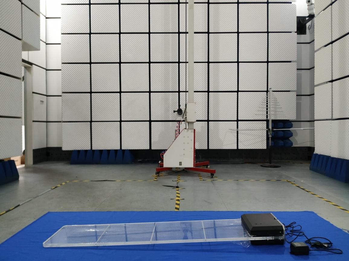
Click to zoom
Application Details
- Equipment Class
- DXX - Part 15 Low Power Communication Device Transmitter
- Date of Grant
- Sep 17, 2020
- Application Purpose
- Original Equipment
- Date of Application
- Sep 16, 2020
- Equipment Note
- RF Chrome System
- Frequency Range
- 8.20000000 - 8.20000000
- Country
- China
Documents & Files
Document Text
Text extracted from the exhibit documents filed with the FCC. Open a document above to read the original.
Users Manual
EASRFsystem TST9900S4 InstallationManual ShenzhenYixunTechnologyCo.,Ltd. V1.0 TableofContents SystemOverview.........................................................................................................1 ImportantPrecautions..............................................................................................1 Components...................................................................................................................2 TST9900S4......................................................................................................................3 Assembly.........................................................................................................................5 Wiringdiagram.............................................................................................................6 Standardmode...........................................................................................................6 Anti-noisemode.........................................................................................................7 Specifications.................................................................................................................8 1 Distancbetweenantannasandmetalframeddoor>0.5m.Make surethatmetalframesinthevicinityofthesystemareelectrically connectedtogether. PRECAUTION Thesystemwillbestfunctionifpositionawayfromcashier, computer,datatransmissionline,powercable,fluorescentlight, etc.Tomaximizesensitivity,adistanceofnotlessthan1.0mis recommended. PRECAUTION Toavoidanyinterferencecausedbyotherelectronicappliances, thesystemshouldbepoweredbyanindependentpowersource. Thepowersocketshouldadheretosafetystandardandgrounded. PRECAUTION MonosystemwillreceiveTX/RXsysteminterference,inuseat leasttoensurethatwiththeTX/RXsystembetweenmorethan 10mfromthesafedistance. PRECAUTION Asanexample,ametalfenceisnotfirmlyfittogetheritcouldbya smallmovementreachacapacitancebetweenitspartssothatit actsasaperfecttag.Ifthesignalhasthesamepatternasalabelor hardtagitwouldsetthealarmoff. PRECAUTION SystemOverview TheMONOTransceiversystemisamulti-loopsinglepanel8.2MHzsystemthat providesenhanceddetectionwhencomparedtoaconventionalsystem.Itcan operateonitsownorwithmultiplesystemsbutwithouttheneedof synchronization..Theinstallationissimplewithjustonetuningpointforsensitivity. Eachpanelhaveindependentalarmandwarninglight. ImportantPrecautions 2 Components Motherboard TST9900S4 210*130mm PowerSupply 18Vac,2000mA 90*68*56mm 3 TST9900S4 Receiver: OperatingFrequency8.2MHz Operatingvoltage18Vac Operatingcurrent<450mA±10% Fuse1A,250V,slowblow Operatingfrequency7.5~8.2MHz Detectionrate≥2m/s PowerSupply Inputvoltage100-120Vacor200-240Vac@50–60Hz Outputvoltage18VAC,2000mA Environment: RelativeHumidity0to85%non-condensing OperatingTemperature0ºto50ºC 4 Sensitivitydebugging: SensitivityControlVR1adjuststhesignallevelofthedetectedRFthatisreceivedbythe antenna.VR1isnormallyinthefullCWposition.Thisisthemaximumgainsetting.Ifthereis ahighnoiseenvironment,VR1couldbeadjustedCCWtolowerthesystemgain,thus reducingtheoverallnoiselevel.BeawarethatreducingthegainusingVR1willalsoreduce thedetectionrange. SensitivityTuning: TurnVR1clockwisetoincreasesensitivity TurnVR1anti-clockwisetodecreasesensitivity IfDS1DS2DS3donotlitup,thismeansperfectcondition(nonoise). IfonlyDS1litup,theconditionisgood. WhenDS2andDS3litup,thereishighinterference,mustresolveandreduce sensitivityuntil KeeponlyDS1blinktoensurenormaloperation. AutoResonanceControlandfrequencyselection: jumperAisAutoResonanceControl,Plugin2—3theworkintheAutoResonance Control,whichcanautomaticallylockleverinterferencefrequency,topreventfalse positives.Fisthefrequencyselectionjumper,Plugin2—3theworkinnarrowband, Plugin1—2theworkinbroadband. Thealarmsoundfrequencyandtimeselection: DIPswitchSW1RATEfrequencyselectionforthealarmsound,thedevicehastwo differentalarmsoundfrequency,theusercanchooseaccordingtotheirpreferences alarmsound,TIMESelectthelengthofthealarmsound,3and5second Alarmsoundintensitydebugging: TheVolumeControlVR2isusedtoadjustthevolumelevelofthealarmsounder.VR2is normallyinthefullCWposition.Thisisthemaximumvolumesetting.Ifthevolumehasto bereducedinaparticularstoreenvironment,VR2canbeadjustedCCWuntilthedesired volumeisreached. NoSynchronizing Nointerconnectingcablerequired. Improvesoverallappearance. Reducesinstallationtime. 5 Assembly 6 Wiringdiagram Standardmode Equippedwithabalanceddetectioncapability,butanti-noiseabilityisweak. GNDJ4 J3 7 Anti-noisemode Itcanimprovenoiseimmunity,butwillreducethedetectiondistance. 8 Specifications 9 FCC Statement: This device complies with Part 15 of the FCC rules. Operation is subject to the following two conditions: 1) this device may not cause harmful interference, and 2) this device must accept any interference received, including interference that may cause undesired operation. This equipment has been tested and found to comply with the limits for a Class B digital device, pursuant to Part 15 of the FCC rules. These limits are designed to provide reasonable protection against harmful interference in a residential installation. This equipment generates, uses and can radiate radio frequency energy and if not installed and used in accordance with the instructions, may cause harmful interference to radio communications. However, there is no guarantee that interference will not occur in a particular installation. If this equipment does cause harmful interference to radio or television reception, which can be determined by turning the equipment off and on, the user is encouraged to try correct the interference by one or more of the following measures: - Reorient the receiving antenna. - Increase the separation between the equipment and receiver. - Connect the equipment into and outlet on a circuit different from that to which the receiver is connected. - Consult the dealer or an experienced radio/TV technician for help. Changes or modifications not expressly approved by the party responsibl…
Text truncated - open the document above for the full version.
Attestation Statements
FCC ID :2AXF9-SD-110 Model No.: SD-110, SD-100 All models are electrically identical ,only except model no and appearance of EUT are different. <Signature> Name Wanyou Zhang Title Manager Applicant Company :Shenzhen Yixun Technology Co., Ltd.
Cover Letter(s)
DATE :2020/9/4 FederalCommunicationsCommission Authorization&EvaluationDivision 7345OaklandMillsRoad Columbia,Maryland21046 AuthoritytoActasAgent Onourbehalf,IappointBlueAsiatechnicalservicesLimited.andIOTTestCentreof BlueAsiaNo.448BulongRoad,BantianStreet,LonggangDistrict,Shenzhen(Nameof Agentcompanynameandaddress)toactasouragentinthepreparationofthis applicationforequipmentcertification.Icertifythatsubmitteddocumentsproperlydescribe thedeviceorsystemforwhichequipmentcertificationissought.Ialsocertifythateach unitmanufactured,importedormarketed,asdefinedintheFederalCommunications Commission’sregulationswillhaveaffixedtoitalabelidenticaltothatsubmittedfor approvalwiththisapplication. Forinstanceswhereourauthorizedagentsignstheapplicationforcertificationonour behalf,Iacknowledgethatallresponsibilityforcomplyingwiththetermsandconditions forcertification,stillresideswithShenzhenYixunTechnologyCo.,Ltd.and4th floorofwest,HuoLiBaobuilding,NO.31,GaoxinNorth6Rd, Nanshan,Shenzhen(ApplicantNameandaddress) <Signature> Name WanyouZhang TitleManager ApplicantCompany:ShenzhenYixunTechnologyCo.,Ltd.
External Photos
Model No.: SD-110
ID Label/Location Info
80mm 40mm
Internal Photos
Model No.:SD-110
Test Report
Report No. : BLA-EMC-202008-A0901 BlueAsia Technology Services(Shenzhen) Limited Add:No. 448, Bulong Road, Bantian Street, Longgang District, Shenzhen, China Tel: +86-755-23059481 Email: [email protected] www.cblueasia.com FCC Report Product Name : RF Chrome System Trade mark : Model No. : SD-110, SD-100 FCC ID : 2AXF9-SD-110 Report Number : BLA-EMC-202008-A0901 Date of sample receipt : 2020/8/6 Date of Test : 2020/8/6-2020/9/15 Date of Issue : 2020/9/15 Test standard : FCC CFR Title 47 Part 15 Subpart C Section 15.223 Test result : PASS Prepared for: Shenzhen Yixun Technology Co.,Ltd. 4th floor of west,Huo Li Baobuilding,NO.31,Gaoxin North 6 Rd,Nanshan,Shenzhen Prepared by: BlueAsia of Technical Services(Shenzhen) Co., Ltd. IOT Test Centre of BlueAsia No. 448 Bulong Road, Bantian Street, Longgang District, Shenzhen, China TEL: +86-755-28682673 Compiled by: Review by: Approved by: Date: 2020/9/15 Report No. : BLA-EMC-202008-A0901Page 2 of 31 BlueAsia Technology Services(Shenzhen) Limited Tel: +86-755-23059481 Email: [email protected] www.cblueasia.com 2 Version Version No. Date Description 00 2020/9/15 Original Report No. : BLA-EMC-202008-A0901Page 3 of 31 BlueAsia Technology Services(Shenzhen) Limited Tel: +86-755-23059481 Email: [email protected] www.cblueasia.com 3 Contents Page 1 COVER PAGE ........................................................................................................................................... 1 2 VERSION ...................................................................................................................................................2 3 CONTENTS ...............................................................................................................................................3 4 TEST SUMMARY ......................................................................................................................................4 5 GENERAL INFORMATION .......................................................................................................................5 5.1 GENERAL DESCRIPTION OF EUT ..........................................................................................................5 5.2 TEST MODE .........................................................................................................................................6 5.3 DESCRIPTION OF SUPPORT UNITS ........................................................................................................6 5.4 TEST FACILITY ....................................................................................................................................6 5.5 TEST LOCATION ..................................................................................................................................6 6 TEST INSTRUMENTS LIST ......................................................................................................................7 7 TEST RESULTS AND MEASUREMENT DATA .......................................................................................9 7.1 CONDUCTED EMISSIONS ......................................................................................................................9 7.2 FIELD STRENGTH OF THE FUNDAMENTAL SIGNAL ................................................................................12 7.3 CHANNEL BANDWIDTH .......................................................................................................................14 7.3.1 Radiated Emission Method .........................................................................................................16 8 TEST SETUP PHOTO .............................................................................................................................22 9 EUT CONSTRUCTIONAL DETAILS .......................................................................................................25 Report No. : BLA-EMC-202008-A0901Page 4 of 31 BlueAsia Technology Services(Shenzhen) Limited Tel: +86-755-23059481 Email: [email protected] www.cblueasia.com 4 Test Summary Test Item Section in CFR 47 Result AC Power Line Conducted Emission 15.207 Pass Channel Bandwidth 15.223 (a) Pass Field Strength of the Fundamental Signal 15.223 (a) Pass Spurious Emission 15.209 Pass Pass: The EUT complies with the essential requirements in the standard. Remark: Test according to ANSI C63.10:2013. Measurement Uncertainty Test Item Frequency Range Measurement Uncertainty Notes Radiated Emission 9kHz ~ 30MHz 4.34dB (1) Radiated Emission 30MHz ~ 1000MHz 4.24dB (1) Radiated Emission 1GHz ~ 26.5GHz 4.68dB (1) AC Power Line Conducted Emission 0.15MHz ~ 30MHz 3.45dB(1) Note (1): The measurement uncertainty is for coverage factor of k=2 and a level of confidence of 95%. Report No. : BLA-EMC-202008-A0901Page 5 of 31 BlueAsia Technology Services(Shenzhen) Limited Tel: +86-755-23059481 Email: [email protected] www.cblueasia.com 5 General Information 5.1 General Description of EUT Product Name: RF Chrome System Model No.: SD-110, SD-100 Test Model No.: SD-110 Remark: All above models are identical in the same PCB layout, interior structure and electrical circuits. The differences are product appearance and model name for commercial purpose. Sample(s) Status Engineer sample Hardware: V1.2 Software: V1.2 Operation Frequency: 8.2MHz Channel Numbers: 1 Modulation Type: ASK Antenna Type: External Antenna Antenna Gain: 0.0dBi Power Supply: Model:YDH-1802000 Input:AC220V,50Hz Output:AC18V 2A Remark:The Antenna Gain is supplied by the customer Report No. : BLA-EMC-202008-A0901Page 6 of 31 BlueAsia Technology Services(Shenzhen) Limited Tel: +86-755-23059481 Email: [email protected] www.cblueasia.com 5.2 Test mode Transmitting mode: Keep the EUT in continuously transmitting mode with modulation Remark:All models have been pretest,only worse model SD-110 is reported 5.3 Description of Support Units Manufacturer Description Model Serial Number N/A N/A N/A…
Text truncated - open the document above for the full version.
Test Setup Photos
Model No.: SD-110 Radiated Emission 9KHz-30MHz 30MHz-1GHz Conducted Emission
Contact Information
Applicant
Wanyou Zhang(Manager)
Test Firm
BlueAsia of Technical Services (Shenzhen)Blue Zheng
[email protected]+86 755-23059481-815
Technical Specifications
| # | Rule Parts | Frequency Range | Power Output |
|---|---|---|---|
| 1 | 15C | 8.2 MHz - 8.2 MHz | - |