2AXG5-043007003RIOTRONIC X+ Blaster 915
Maxam Initiation Systems, S.L.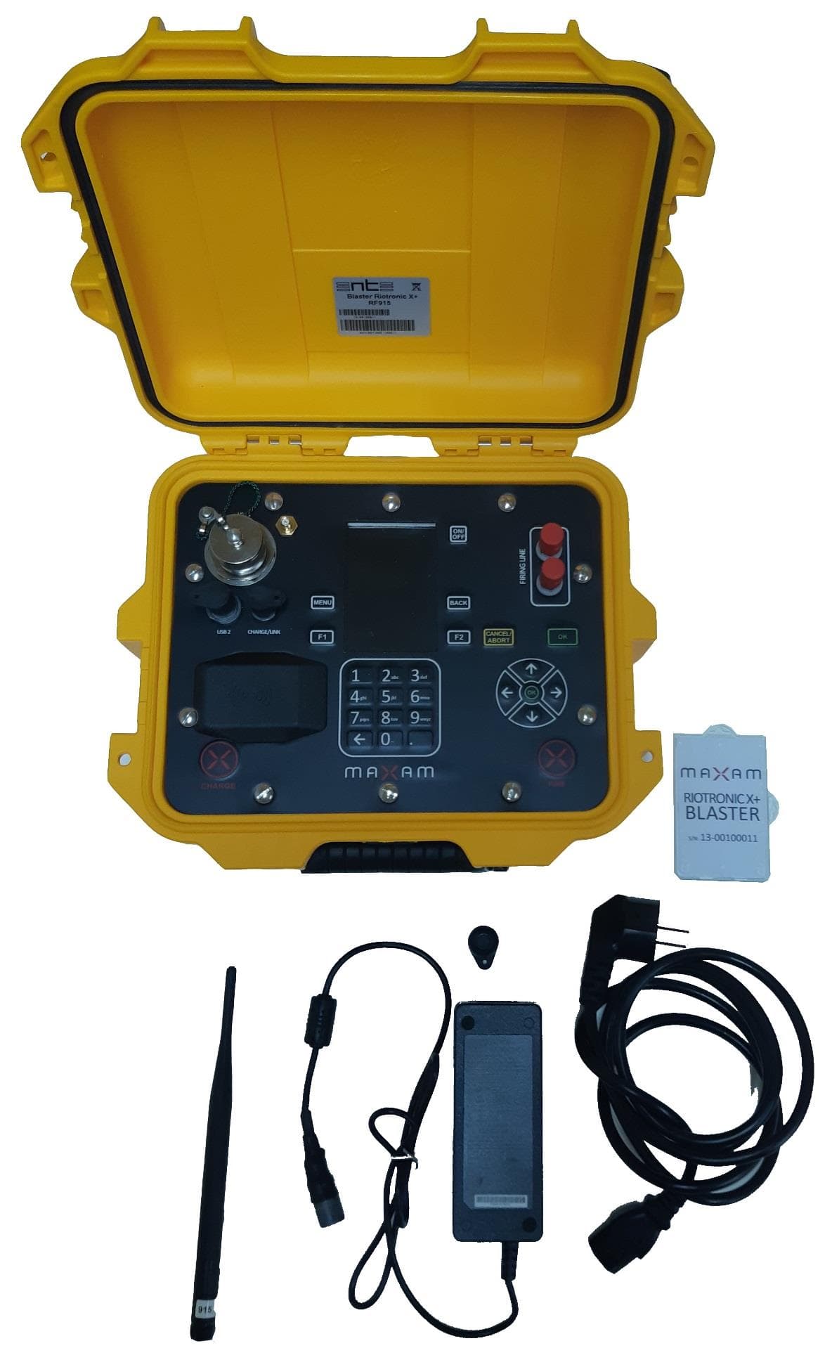
Click to zoom
Application Details
- Equipment Class
- DTS - Digital Transmission System
- Date of Grant
- Oct 29, 2020
- Application Purpose
- Original Equipment
- Date of Application
- Oct 29, 2020
- Equipment Note
- RIOTRONIC X+ Blaster 915
- Frequency Range
- 902.50000000 - 927.00000000
- Country
- Spain
Documents & Files
Document Text
Text extracted from the exhibit documents filed with the FCC. Open a document above to read the original.
Users Manual
RIOTRONIC X+ SYSTEM User manual July 2020 Version 1.1 1 RIOTRONIC X+ User Manual Disclaimer: MAXAM takes all reasonable efforts to ensure an accurate understanding of client requirements. The information contained in this report is as accurate and up-to-date as possible based on this understanding. MAXAM accepts no liability to any person for any injury, loss or damage resulting from the use of or reliance upon the information contained in this report or for any injury, loss or damage resulting from the omission of any information in this report. No expressed or implied warranties are given other than those implied mandatory by territory legislation. 2 RIOTRONIC X+ User Manual Table of contents: Disclaimer: ....................................................................................................................... 1 1. Safety ........................................................................................................................ 8 2. Introduction ............................................................................................................. 9 2.1. RIOTRONIC X+ Detonator .................................................................................... 10 2.1.1. Detonator Technical Specifications ..................................................... 12 2.1.2. Label.......................................................................................................... 12 2.1.3. Connector ................................................................................................. 12 2.2. RIOTRONIC X+ Accessories ................................................................................ 13 2.2.1. Safety key ............................................................................................................ 13 2.2.2. Bus-line ..................................................................................................... 14 2.2.3. Charger ..................................................................................................... 14 2.2.4. Replacement connector .......................................................................... 14 2.2.5. Equipment-PC USB cable ........................................................................ 15 2.3. RIOTRONIC SW software .................................................................................... 15 3. Operation Procedure ............................................................................................. 16 3.1. General procedure for a blast using RIOTRONIC X+ ................................... 16 3.1.1. Defining a blast plan ............................................................................... 16 3.1.2. Covering Risk Assessment ..................................................................... 16 3.1.3. Preparing the Equipment ....................................................................... 16 3.1.4. Product distribution ............................................................................... 16 3.1.5. Priming, loading and stemming the hole .............................................. 17 3.1.6. Programming and connecting ............................................................... 17 3.1.7. Testing lines, detonators and connections .......................................... 17 3.1.8. Firing the blast ........................................................................................ 18 3.1.9. Post blast inspection and solving cut-offs/misfires ........................... 18 3.1.10. Blast history/record download ............................................................. 18 3.2. Operating procedure ............................................................................................. 19 3.2.1. Blasting plan ............................................................................................ 19 3.2.2. Detonator testing ................................................................................... 20 3.2.3. Risk assessment ...................................................................................... 21 3 RIOTRONIC X+ User Manual 3.2.4. Priming .................................................................................................... 22 3.2.5. Reels ......................................................................................................... 22 3.2.6. Packaged Explosives .............................................................................. 23 3.2.7. Cast Booster ............................................................................................ 23 3.2.8. Loading .................................................................................................... 24 3.2.9. Stemming ................................................................................................ 24 3.2.10. Precautions during operation .............................................................. 25 4. Best Practices ......................................................................................................... 25 4.1. Before you proceed to the blast site, make sure that ........................ 25 4.2. During logging ........................................................................................ 26 4.3. After logging ........................................................................................... 26 5. System limits for the RIOTRONIC X+ Logger .................................................... 27 5.1. Positioning of RIOTRONIC X+ Loggers ................................................ 27 5.2. Connect – Reconnect the RIOTRONIC X+ Logger to the BUS LINE .. 27 5.3. Extension of BUS LINE wire .................................................................. 27 5.4. System limits for the RIOTRONIC X+ Blaster .................................... 28 5.5. General planning for connection .......................................................... 28 5.6. Before shot ...............................................................................…
Text truncated - open the document above for the full version.
Cover Letter(s)
CSF410-TCB 3.0 Page 1 of 5 FORM CSF410-TCB FCC APPLICATION FORM This form constitutes the certification agreement between Element Materials Technology and the Applicant and is required for every application. Please ensure accuracy when completing this form because the content is used to make the FCC upload to the FCC eFiling system. Please complete the relevant sections in the tables below. Guidance on each numbered section of this form is provided at the end of the document. Please contact Element if you have any further questions. Applicant business details 1. Applicant’s complete, legal business name. Maxam Initiation Systems, S.L. 2. Applicant’s mailing address (Line 1) Avenida de Partenon 16 3. Applicant’s mailing address (Line 2) 4. City, State, Zip (or postal code) 28042 Madrid Spain 5. Name, Title of Person registered with the FCC to receive the grant. Jose M. Vega 6. Phone No. (Area/Country /City Code, Number, Ext). 7. Fax No. (Area/Country/City Code, Number, Ext. 8. Internet email address [email protected] 9. Applicants FRN # (FCC registered number) 0029512621 Authorised agent details Only to be completed where a third party is used to make an application on behalf of the Applicant 10. Name, Title 11. Mailing address (Line 1) 12. City, State, Zip (or postal code) 13. Phone No. (Area/Country /City Code, Number, Ext). 14. Internet email address Product details 15. Equipment model RIOTRONIC X+ Blaster 915 16. FCC ID Number GRANTEE CODE 2AXG5 17. FCC ID equipment code (Max. 14 Chars.) -043007003 18. FCC ID Rule part. (15.249, 15.247, etc.) 15.225 19. Type of grant ☒Original Grant ☐ Class II Permissive Change ☐ Class III Permissive Change FORM CSF410-TCB FCC APPLICATION FORM CSF410-TCB 3.0 Page 2 of 5 ☐ Change in ID (Provide original FCC ID number and grant date (yyyy/mm/dd: ) 20. Seeking modular approval? ☐ Yes ☒ No 21. Are there provisions for using this radio within 20 cm of the head or torso? (belt clips, holster, headset, etc.) ☐ Yes ☒ No Other information 22. Do you wish to hold some information permanently confidential? ☒ Yes ☐ No 23. Do you wish to hold some information confidential short-term? ☒ Yes ☐ No Notes or comments Free field FORM CSF410-TCB FCC APPLICATION FORM CSF410-TCB 3.0 Page 3 of 5 FCC application and signature Read each certification carefully before answering and signing this application. WILLFUL FALSE STATEMENTS MADE ON THIS FORM ARE PUNISHABLE BY FINE AND/OR IMPRISONMENT (U.S. CODE, TITLE 18, SECTION 1001), AND/OR REVOCATION OF ANY STATION LICENSE OR CONSTRUCTION PERMIT (U.S. CODE, TITLE 47, SECTION 312(a)(1)), AND/OR FORFEITURE (U.S. CODE, TITLE 47, SECTION 503). 24. SECTION 5301 (ANTI-DRUG ABUSE) CERTIFICATION The applicant must certify that neither the applicant nor any party to the application is subject to a denial of Federal benefits, that include FCC benefits, pursuant to Section 5301 of the Anti-Drug Abuse Act of 1988, 21 U.S.C. §862 because of a conviction for possession or distribution of a controlled substance. See 47 CFR 1.2002(b) for the definition of a “party” for these purposes. Does the applicant or authorized agent so certify? ☒ Yes ☐ No 25. NOT PREVIOUSLY SUBMITTED NOR DENIED I certify that this product has not been previously submitted to the FCC nor to another TCB for certification. I further certify that this product has not previously been dismissed nor denied by the FCC nor by another TCB. 26. APPLICANT/AGENT ATTESTATION I certify that I am authorized to sign this application. All of the statements herein and the exhibits attached hereto are true and correct to the best of my knowledge and belief. In accepting a Grant of Equipment Authorization issued by the TCB as a result of the representations made in this application, the applicant is responsible for (1) labeling the equipment with the exact FCC ID specified in this application, (2) compliance statement labeling pursuant to the applicable rules, and (3) compliance of the equipment with the applicable technical rules. If the applicant is not the actual manufacturer of the equipment, appropriate arrangements have been made with the manufacturer to ensure that production units of this equipment will continue to comply with the FCC’s technical requirements. Authorizing an agent to sign this application, is done solely at the applicant’s discretion; however, the applicant remains responsible for all statements in this application. If an agent has signed this application on behalf of the applicant, a written letter of authorization which includes information to enable the agent to respond to the above Section 5301 (Anti-Drug Abuse) Certification statement has been provided by the applicant. It is understood that the letter of authorization must be submitted to the FCC upon request, and that the TCB reserves the right to contact the applicant directly at any time. 27. IEC/ISO 17065 REQUIREMENTS By signing this application, the applicant agrees to the following requirements and conditions: a. The applicant will always comply with the relevant provisions of the certification programme, and the requirements of the regulatory body under which certification is granted, including implementing appropriate changes when they are communicated by the Element Certification Body. b. If the certification applies to ongoing production, the certified product continues to fulfil the product requirements. c. The applicant will make all necessary arrangements for: i) the conduct of the evaluation, including provision for examining documentation and records and access to and access to the relevant equipment, location(s), area(s), personnel, and applicant's subcontractors; ii) investigation of complaints; iii) the participation of observers, if applicable. d. The applicant makes claims regarding certification consistent with the scope of certification. e. The applicant will not use its product certification in such a manner as to bring the Element Certification Body into disrepute and will not make any s…
Text truncated - open the document above for the full version.
Cover Letter(s)
REFERENCING RADIO PARAMETER TEST DATA October 5, 2020 Product: RIOTRONIC X+ Blaster 915 FCC ID: 2AXG5-043007003 This Technical Justification Letter is for Maxam’s product “RIOTRONIC X+ Logger” with FCC ID: 2AXG5-043007003. The purpose of this letter is to justify the re-use of test data from original test reports with reference TRA-049647-45-00A and reference TRA- 049647-45-02A for product “RIOTRONIC X+ Remote 915” with FCC ID: 2AXG5- 043008003. The RIOTRONIC X+ Blaster 915 (new product) is a 915MHz transmitter with DTS equipment class and an inductive tag with a 13.56MHz transmitter with DXX equipment class. We, Maxam Initiation Systems, S.L. (the applicant) take full responsibility that the test data as referenced represents compliance for the new FCC ID. The differences between the two products are as follows. The original product under FCC ID: 2AXG5-043008003 contains a 915MHz transmitter and NFC transmitter. The new product under FCC ID: 2AXG5-043007003 contains 915MHz and NFC transmitters. The 915MHz transmitter between both products is the same. The NFC transmitter has been fully tested on both products. In order to reuse the conducted radio testing, spot check verification has been performed for fundamental output power and radiated spurious emissions, as detailed by the below tables. Original Transmitter : 915MHz FCC ID: 2AXG5-043008003 Report: TRA-049647-45-00A New Transmitter : 915MHz FCC ID: 2AXG5-043007003 Report: TRA-049647-45-04A Radiated Spurious Emissions Radiated Spurious Emissions Occupied bandwidth Testing to be carried over Conducted Carrier Power Conducted Carrier Power Conducted / radiated RF power out-of- band Testing to be carried over Power spectral density, conducted Testing to be carried over As per the above table the testing to be carried over from the original test report is the occupied bandwidth, conducted RF power out-of-band and conducted power spectral density tests. Spot check verification on fundamental power and radiated spurious emissions has rendered these tests still applicable to the RIOTRONIC X+ Blaster 915 product. Yours faithfully, José M. Vega ELIS Project Manager Maxam Initiation Systems, S.L.
Cover Letter(s)
Request for Confidentiality Letter-FCC October 6, 2020 Federal Communications Commission Authorization and Evaluation Division 7435 Oakland Mills Road Columbia, Maryland 21046 Re: Request for confidentiality FCC ID: 2AXG5-043007003 Model: Riotronic X+ Blaster 915 To whom it may concern, We hereby respectfully request that under the provision of 47 CFR 0.459 and 0.457(d) all documents listed below and attached with this application for certification be provided with: Long-term confidential status: Bill of Materials Frequency Block Diagram PCB layout Schematics of Radio Operational description Short-term confidential status: User Manual Any exhibit / information for which we have requested confidentiality, but which may not be accorded such treatment by the FCC, should be returned to us. The documents listed above contain trade secrets that are treated as confidential by us. Substantial competitive harm to us could result should they be made available to the public. Sincerely, José M. Vega ELIS Project Manager Maxam Initiation Systems, S.L.
Cover Letter(s)
APPLICANT LETTER HEAD LETTER OF AGENCY October 5, 2020 Element Materials Technology 100 Frobisher Business Park Malvern Worcestershire WR14 1BX UK To Whom It May Concern: We certify that we are not subject to denial of federal benefits, that includes FCC benefits, pursuant to Section 5301 of the Anti-Drug Abuse ACT of 1988, U.S.C. 862. Further, no party, as defined in 47 CFR 1.2002(b), to the application, is subject to denial of federal benefits, that includes FCC benefits. Thank you for your attention to this matter. Yours faithfully José M. Vega ELIS Project Manager Maxam Initiation Systems, S.L.
External Photos
EXTERNAL PHOTOS BLASTER RF915 Rev.: 0 (15/04/2020) EN Rev.: Date Control of changes and modifications. 0 15/04/2020 Creation and revision of the document. Prepared Reviewed Approved Jon Eritz Fernández Linares Electronic Professional 15/04/2020 © MAXAM Corp Holding, S.L. This document is owned by MAXAM, and is for the exclusive use of its staff. The information contained herein may not be reproduced or transmitted by any means outside of MAXAM without express permission. The controlled copy of this document is officially published in MAXAM Place in its electronic format. External Photos – Blaster RF915 15/04/2020 2 | 13 INDEX 1. General view. ................................................................................................................................................................ 3 2. Equipment. ..................................................................................................................................................................... 4 2.1. Front view. ................................................................................................................................................................. 4 2.2. Back view. .................................................................................................................................................................. 5 2.3. Left view. .................................................................................................................................................................... 6 2.4. Right view. ................................................................................................................................................................. 7 2.5. Top view open. ........................................................................................................................................................ 8 2.6. Top view closed. ...................................................................................................................................................... 9 2.7. Bottom view. .......................................................................................................................................................... 10 3. Accessories. ................................................................................................................................................................... 11 3.1. Charger. ...................................................................................................................................................................... 11 3.2. Antenna. .....................................................................................................................................................................12 3.3. NFC card. .................................................................................................................................................................. 13 External Photos – Blaster RF915 15/04/2020 3 | 13 1. General view. External Photos – Blaster RF915 15/04/2020 4 | 13 2. Equipment. 2.1. Front view. External Photos – Blaster RF915 15/04/2020 5 | 13 2.2. Back view. External Photos – Blaster RF915 15/04/2020 6 | 13 2.3. Left view. External Photos – Blaster RF915 15/04/2020 7 | 13 2.4. Right view. External Photos – Blaster RF915 15/04/2020 8 | 13 2.5. Top view open. External Photos – Blaster RF915 15/04/2020 9 | 13 2.6. Top view closed. External Photos – Blaster RF915 15/04/2020 10 | 13 2.7. Bottom view. External Photos – Blaster RF915 15/04/2020 11 | 13 3. Accessories. 3.1. Charger. External Photos – Blaster RF915 15/04/2020 12 | 13 3.2. Antenna. External Photos – Blaster RF915 15/04/2020 13 | 13 3.3. NFC card.
ID Label/Location Info
LOCATION OF INFORMATION LABELS RIOTRONIC X+ Location_information_labels RT X+ Rev.: 0.0 (05/10/2020) EN Rev.: Date Control of relevant modifications and changes. 2.0 1.2 1.1 1.0 0 05/10/2020 Creation and revision of the document. Prepared Reviewed Approved Raúl Rodríguez de la Fuente Electronic Engineering Profesional 05/10/2020 Raúl Rodríguez de la Fuente Electronic Engineering Professional 05/10/2020 Jose Manuel Vega Project Manager 05/10/2020 © MAXAM Corp Holding, S.L. This document is owned by MAXAM, and is for the exclusive use of its staff. The information contained herein may not be reproduced or transmitted by any means outside of MAXAM without express permission. The controlled copy of this document is officially published in MAXAM Place in its electronic format. Location information labels 05/10/2020 2 | 6 INDEX 1. Objective. ........................................................................................................................................................................ 3 2. RIOTRONIC X + BLASTER Labels .................................................................................................................... 3 3. RIOTRONIC X + LOGGER Label ........................................................................................................................ 5 4. RIOTRONIC X + REMOTE Label ....................................................................................................................... 6 Location information labels 05/10/2020 3 | 6 1. Objective. The objective of this document is to generate a general indication of where each of the information labels of the RT X + equipment should be placed. These labels will contain the essential information on the use of the equipment as well as some technical aspects necessary to control. 2. RIOTRONIC X + BLASTER Labels Outer label: The RIOTRONIC X + BLASTER has two information labels. The outer label will be located on the outside of the briefcase, located in the center of the outer lid of the equipment. This label will contain information regarding the family of equipment in question, the type of equipment it is, the MAXAM logo and the frequency of work at which it works. Location information labels 05/10/2020 4 | 6 Internal label The inner label will be located in the central part of the equipment cover. This label will contain all the information on the use, maintenance and characteristics of the equipment. In addition, this label will indicate dates of maintenance, manufacture, the unique serial number, the validation entities, as well as other series of specific data of each equipment. Location information labels 05/10/2020 5 | 6 3. RIOTRONIC X + LOGGER Label Outer label The RIOTRONIC X + LOGGER equipment only has an information label. In it, you can find the same information as on the inside label of the RIOTRONIC X + BLASTER, therefore, it will contain all the information on the use, maintenance and characteristics of the equipment. In addition, this label will indicate dates of maintenance, manufacture, the unique serial number, the validation entities, as well as other series of specific data of each equipment. Location information labels 05/10/2020 6 | 6 4. RIOTRONIC X + REMOTE Label Outer label The RIOTRONIC X + REMOTE equipment only has an information label. In it, you can find the same information as on the inside label of the RIOTRONIC X + BLASTER, therefore, it will contain all the information on the use, maintenance and characteristics of the equipment. In addition, this label will indicate dates of maintenance, manufacture, the unique serial number, the validation entities, as well as other series of specific data of each equipment.
Internal Photos
INTERNAL PHOTOS BLASTER RF915 Rev.: 0 (16/04/2020) EN Rev.: Date Control of changes and modifications. 0 16/04/2020 Creation and revision of the document. Prepared Reviewed Approved Jon Eritz Fernández Linares Electronic Professional 16/04/2020 © MAXAM Corp Holding, S.L. This document is owned by MAXAM, and is for the exclusive use of its staff. The information contained herein may not be reproduced or transmitted by any means outside of MAXAM without express permission. The controlled copy of this document is officially published in MAXAM Place in its electronic format. Internal Photos – Blaster RF915 16/04/2020 2 | 13 INDEX 1. General view. ................................................................................................................................................................ 3 2. Mainboard module. ................................................................................................................................................... 5 2.1. Top view. ..................................................................................................................................................................... 5 2.2. Bottom view. ............................................................................................................................................................ 6 3. Keyboard module. ...................................................................................................................................................... 7 3.1. Top view. ..................................................................................................................................................................... 7 3.2. Bottom view. ............................................................................................................................................................ 8 4. NFC module. .................................................................................................................................................................. 9 4.1. Top view. ..................................................................................................................................................................... 9 4.2. Bottom view. ............................................................................................................................................................ 9 4.3. Component identification. ............................................................................................................................. 10 5. RF915 module. .............................................................................................................................................................. 11 5.1. Top view. .................................................................................................................................................................... 11 5.2. Bottom view. ...........................................................................................................................................................12 5.3. Component identification. ............................................................................................................................. 13 Internal Photos – Blaster RF915 16/04/2020 3 | 13 1. General view. Internal Photos – Blaster RF915 16/04/2020 4 | 13 Internal Photos – Blaster RF915 16/04/2020 5 | 13 2. Mainboard module. 2.1. Top view. Internal Photos – Blaster RF915 16/04/2020 6 | 13 2.2. Bottom view. Internal Photos – Blaster RF915 16/04/2020 7 | 13 3. Keyboard module. 3.1. Top view. Internal Photos – Blaster RF915 16/04/2020 8 | 13 3.2. Bottom view. Internal Photos – Blaster RF915 16/04/2020 9 | 13 4. NFC module. 4.1. Top view. 4.2. Bottom view. Internal Photos – Blaster RF915 16/04/2020 10 | 13 4.3. Component identification. ANTENNA MODULE ANTENNA CABLE Internal Photos – Blaster RF915 16/04/2020 11 | 13 5. RF915 module. 5.1. Top view. Internal Photos – Blaster RF915 16/04/2020 12 | 13 5.2. Bottom view. Internal Photos – Blaster RF915 16/04/2020 13 | 13 5.3. Component identification. ANTENNA CABLE MODULE ANTENNA
RF Exposure Info
Report Number: TRA-049647-45-04B RF915 7.1 Page 25 of 26 14 RF Exposure General SAR test reduction & exclusion guidance KDB 447498 Section 4.3 General SAR test reduction and exclusion guidance For Standalone SAR exclusion consideration, when SAR Exclusion Threshold requirement in KDB 447498 is satisfied, standalone SAR evaluation for general population exposure conditions by measurement or numerical simulation is not required. The SAR Test Exclusion Threshold for frequencies in the range 100 MHz to 6 GHz, and for test separation distance of ≤ 50 mm, is determined as follows. SAR Exclusion Threshold (SARET) = (NT x TSD A ) / √ f GHz Where, NT = Numeric Threshold (3.0 for 1-g SAR and 7.5 for 10-g SAR) TSD A = Minimum Test separation distance or 50 mm (whichever is lower) f GHz = Transmit frequency in GHz Channel Frequency (MHz) Maximum Conducted Power (mW) SAR Exclusion Threshold at 10 mm (mW) SAR Evaluation 915 15.7 31.4 Not Required Therefore standalone SAR evaluation for general population exposure conditions by measurement or numerical simulation is not required.
RF Exposure Info
Report Number: TRA-049647-45-06B RF914 6.0 Page 33 of 33 17 RF Exposure RF EXPOSURE TECHNICAL BRIEF RSS-102 issue 5 2.5.1 Exemption Limits for Routine Evaluation – SAR Evaluation SAR evaluation is required if the separation distance between the user and/or bystander and the antenna and/or radiating element of the device is less than or equal to 20 cm, except when the device operates at or below the applicable output power level (adjusted for tune-up tolerance) for the specified separation distance. Channel (MHz) EIRP (mW) SAR Exclusion Threshold at a distance of 5 mm (mW) SAR Evaluation 13.56 0.0000012706 71.0 Not Required
Test Report
RF915 7.1 Report on the Radio Testing For Maxam Initiation Systems, S. L on RIOTRONIC X+ BLASTER 915 Report no. TRA-049647-45-04B 27th October 2020 RF915 7.1 REPORT ON THE RADIO TESTING OF A Maxam Initiation Systems, S. L RIOTRONIC X+ BLASTER 915 WITH RESPECT TO SELECTED CLAUSES OF SPECIFICATION FCC 47CFR 15.247 & ISED RSS-247 TEST DATE: 2020/09/28 - 2020/10/21 Tested by: D Garvey Written by: D Garvey Radio Test Engineer Approved by: K J Anderson Principal Engineer, EMC and Radio Date: 27th October 2020 Disclaimers: [1] THIS DOCUMENT MAY BE REPRODUCED ONLY IN ITS ENTIRETY AND WITHOUT CHANGE [2] THE RESULTS CONTAINED IN THIS DOCUMENT RELATE ONLY TO THE ITEM(S) TESTED Report Number: TRA-049647-45-04B Issue: B Report Number: TRA-049647-45-04B RF915 7.1 Page 3 of 25 1 Revision Record Issue Number I…
Text truncated - open the document above for the full version.
Contact Information
Applicant
Jose M Vega
Test Firm
Element Materials Technology Warwick LtdKeith Wright
Technical Specifications
| # | Rule Parts | Frequency Range | Power Output |
|---|---|---|---|
| 1 | 15C | 902.5 MHz - 927 MHz | 15.70 mW |
Other Applications from Maxam Initiation Systems, S.L.
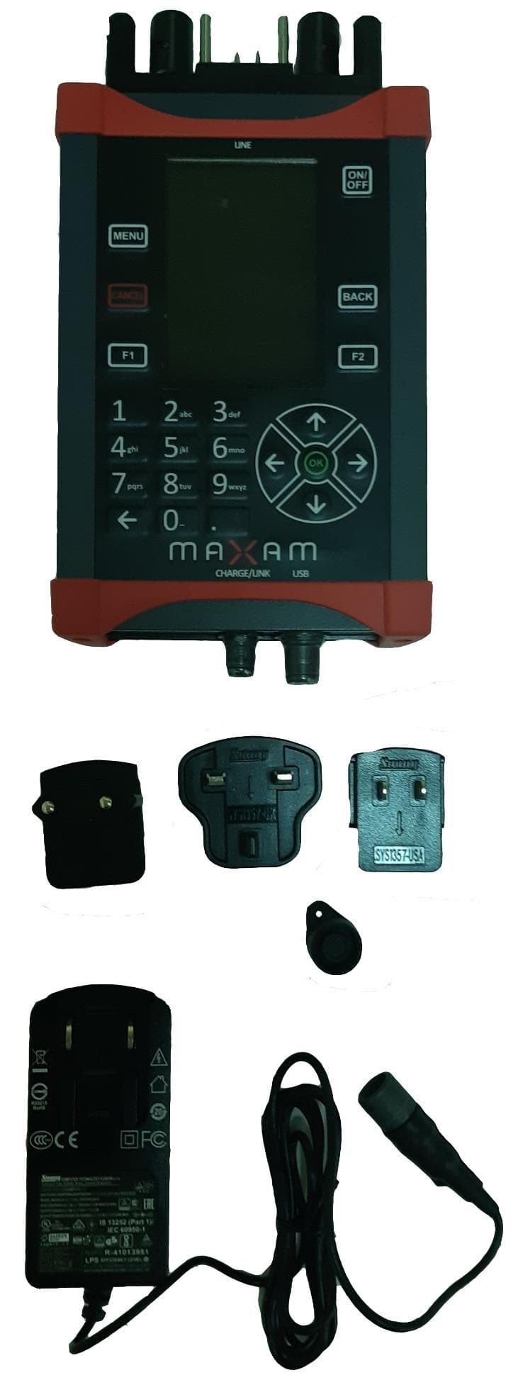
2AXG5-043006001
Oct 29, 2020RIOTRONIC X+ Logger
Equipment Class
DXX - Part 15 Low Power Communication Device Transmitter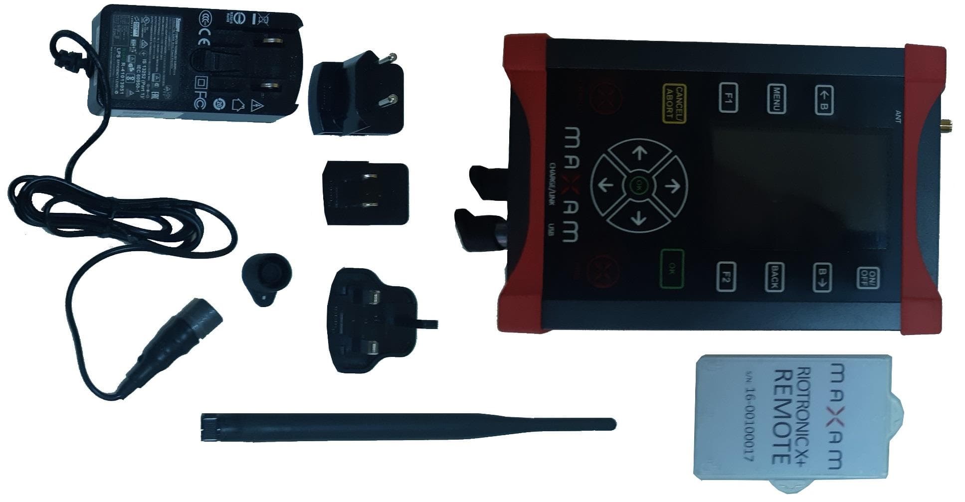
2AXG5-043008003
Oct 29, 2020RIOTRONIC X+ Remote 915
Equipment Class
DTS - Digital Transmission System