2AXIR-S-103Microphone
Shenzhen BAOBAOMI Electronic Technology Co.,Ltd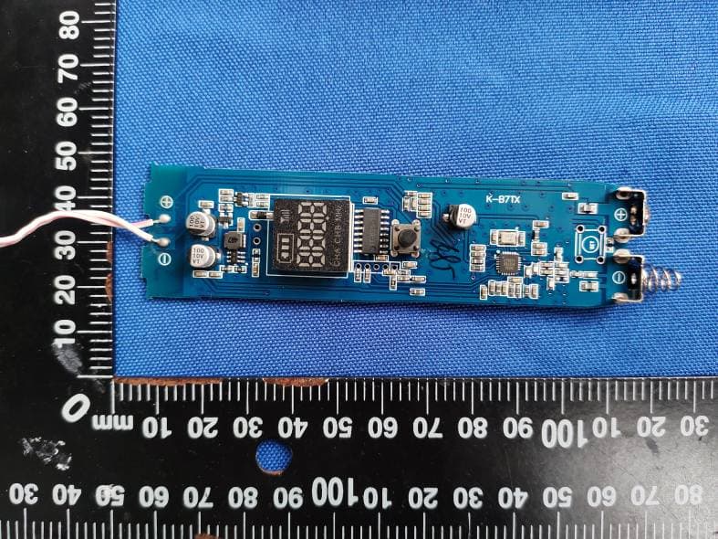
Click to zoom
Application Details
- Equipment Class
- DWM - Part 15 Wireless Microphone
- Date of Grant
- Sep 21, 2020
- Application Purpose
- Original Equipment
- Date of Application
- Sep 20, 2020
- Equipment Note
- Microphone
- Frequency Range
- 470.10000000 - 607.90000000
- Country
- China
Documents & Files
Document Text
Text extracted from the exhibit documents filed with the FCC. Open a document above to read the original.
Users Manual
Entertainment System of Family KTV Bring happiness home Professional wireless microphone equipment for karaoke Thanks for purchasing our product. In order to fully explore the whole functions of our product, please refer to the instructions carefully, complete the setup correctly and keep this instruction for future reference. Product Instructions With Microphone S-103 1 Diagram on Function of Host Machine Bring happiness home A Microphone Receiving Light B Microphone Receiving Light Power in dicator Light Microphone Sound Sensor Light Wired Microphone socket Wired Microphone Volume A Microphone Volume Echo adjustment Music Volume B Microphone Volume Turn on the machine, power indicator light is red. Turn on the switches of wireless microphone A or B, the corresponding A or B microphone receiving light is green. Speaking to microphone, sound sensor light is on when microphone is in operating order. MIC.VOL, a knob adjusts volume of wired microphone. VOL.A, a knob adjusts volume of A wireless microphone. VOL.B, a knob adjusts volume of B wireless microphone. ECHO, a knob adjusts the volume of echo. MUSIC, a knob adjusts input audio source. 2 Diagram on Function of Host Machine Bring happiness home Audio input 6.5MM output Power switch Receiver frequency Power socket Audio output POWER, Power switch R+L IN, Audio input R+L OUT, Audio output R+L OUT, 6.5MM output DC, Power socket When the power is on, Bluetooth is on. 3 Diagram on Function of Microphone Bring happiness home Metal net Masks Frequency Display ON-OFF Battery Room (interior) Tail Cap 4 Schematic Illustration of Audio Cable Connecting Karaoke Bring happiness home TV Computer mobile phone Set Top Box(STB) Projector earphone socket, audio output, AV output, video or audio output Audio input Power Attention: wirings for connection are determined by audio source device and specific circumstances of audio sockets. Connection method: 1.Using the complimentary audio cable connects one of the earphone socket, audio output, AV output or video & audio output and the audio input socket of R+L IN. 2.Then, connecting audio output socket of R+L OUT in host machine and audio input. 3.Connecting to the power source for host machine, inserting AA battery in microphone, the equipment is ready to use. 5 Schematic Illustration of Bluetooth connecting Karaoke Bring happiness home Bluetooth search (playing sources devices) Attention: wirings for connection are determined by audio source device and specific circumstances of audio sockets. TV Tablet mobile phone Set Top Box(STB) Projector Power Audio input Connection method: 1.Playing sources devices open Bluetooth to search devices. 2.Searching the Bluetooth of microphone's host machine. 3.Completing the matching of playing sources devices and microphone. 4.Then, connecting audio output socket of R+L OUT in host machine and audio input. 5.Connecting to the power source for host machine, inserting AA battery in microphone, the equipment is ready to use. 6 Instruction and Connection Manual Bring happiness home 1.Please place host machine (receiver) near desktop or multimedia sp- eakers, connect the power cord. And use the audio cable provided by the manufacture connecting machine’s R+L OUT at one end and MIC IN of desktop or R+L IN of multimedia speakers at the other end. Switching on the power of host machine (receiver), power indicator light will be on and the machine will be in standby mode. (*To ensure a favorable signal condition, you'd better not place the rec- eiver at dead range.) 2.Open battery cover of handheld microphone, insert batteries into bat- tery holder and close the cover. (* There are electrode tab on batteries and the cover, please do not ass- emble batteries reversely.) 3.Switching on the NO gear of handheld microphone, the handheld dis- play lightens. Meanwhile, the corresponding indicator light of host mac- hine (receiver) will be lit as receiving effective signal from microphone. Adjust volume knob of channel and pro amplifier appropriately to make adequate volume for system. At this time, speaking to the microphone, a voice comes out. 4.When red light of handheld microphone is on for a long time, the batt- ery is under voltage, and we need to change a new battery. 5.There is an audio output socket design on the receiver to meet the need of playing in diverse broadcasting, sound recording devices and occasions. 6.Additional function of blamp squelch adjustment enables the machine to effectively strengthen anti – interference receiving feature. 7 Technical Indicators Bring happiness home Desk Type Receiver Receiving Frequency Frequency Stability: <0.002% Sensitivity: 2/MV Adjacent Frequency Interference Ratio: >90DB Mirror Interference Ratio: >88DB Signal-noise Ratio: >95DB Audio Output: 0-300MV Operating Range: 10-30 meters in standard conditions Receiving Channel: Line 2 Supply Voltage: AC/100-240V Bluetooth: 4.1 Antenna: built-in type Comprehensive Index Carrier Frequency:470-608MHZ Frequency Stability: <0.002% Transmitted Power: 16MW Current Dissipation: <25MA Sputious Emission: < principal wave 40DB Standard: fixed frequency Vibration Pickup: 600ΩONE-TOUCH Battery: 3.0V Dynamic Range: >95DB Systematic Distortion:(<1% , 1KHZ modulation) Frequency Response:50HZ-18KHZ (3±DB) *NOTE: The parameter requires to be modified due to the improvement of the machine. All specification supplied herein are subject to change without notice at any time. :470-608MH Z Microphone 8 Safety Instructions Bring happiness home Detail Guide: please read the safety operating instructions carefully before using this product. Preservation Guide: please put the instruction in a safe place so as for future reference. Caution: please refer to the cautions labeled on the machine or on the operating procedures. Following Guide: please observe all operating procedures and instruc- tions. Using and Preservation: please not place or use the machine in envir- onment of high degree humidity, electromagnetic field…
Text truncated - open the document above for the full version.
Cover Letter(s)
Shenzhen BAOBAOMI Electronic Technology Co.,Ltd A4-2D, 12th Floor, Building 4, Seger Technology Park, Huaqiang North Road, Huaqiang North Street, Futian District, Shenzhen, China Tel: +86-13427430152 E-mail: [email protected] Series Models Description Date: 2020/09/18 To: Federal Communications Commission Authorization and Evaluation Division 7435 Oakland Mills Road Columbia, MD FCC ID: 2AXIR-S-103 Dear Sir/Madam, We, Shenzhen BAOBAOMI Electronic Technology Co.,Ltd Hereby declares the following statement for Federal Communications Commission, PCB board, circuit, structure and internal of these model(s) are the same, Only color and model number is different for these model: Product name:Microphone Model no.:S-103, D-300, WM-2, GT-200, J5, MU-898, S-9, S-10, G8, J10 Sincerely, Name:Haijing Wu Company:Shenzhen BAOBAOMI Electronic Technology Co.,Ltd Address:A4-2D, 12th Floor, Building 4, Seger Technology Park, Huaqiang North Road, Huaqiang North Street, Futian District, Shenzhen, China Phone:+86-13427430152 Fax:N/A E-Mail:[email protected]
Cover Letter(s)
CONFIDENTIALITY REQUEST for Certification Service in USA Federal Communication Commission Equipment Authorization Division, Application Processing Branch 7435 Oakland Mills Road Columbia, MD 21046 Date: Sep. 18, 2020 TO WHOM IT MAY CONCERN Pursuant to Paragraphs §0.457 and 0.459 of the Commission’s Rules (47 C.F.R.) and Section §552(b)(4) of the Freedom of Information Act, we requests confidentiality for the following products: FCC IDModel name 2AXIR-S-103S-103, D-300, WM-2, GT-200, J5, MU-898, S-9, S-10, G8, J10 For the product stated above, we request that the following information be held confidential; Exhibits Long-Term Confidentiality Short-Term Confidentiality Short-Term Confidentiality Days External Photos Internal Photos Block Diagram Schematics Test Setup Photos User’s Manual Parts List Tune Up Operational Descriptions The long-term confidentiality exhibits contain our trade secrets and proprietary information that could be of benefit to our competitors. The short-term confidentiality on the basis of ensuring that business sensitive information remains confidential until the actual marketing of our new device. If you have any questions, please feel free to contact me at the address shown below. Sincerely, Name:Haijing Wu Company:Shenzhen BAOBAOMI Electronic Technology Co.,Ltd Address:A4-2D, 12th Floor, Building 4, Seger Technology Park, Huaqiang North Road, Huaqiang North Street, Futian District, Shenzhen, China Phone:+86-13427430152 Fax:N/A E-Mail:[email protected]
Cover Letter(s)
Shenzhen BAOBAOMI Electronic Technology Co.,Ltd A4-2D, 12th Floor, Building 4, Seger Technology Park, Huaqiang North Road, Huaqiang North Street, Futian District, Shenzhen, China Tel: +86-13427430152 E-mail: [email protected] Federal Communications Commission Authorization and Evaluation Division Equipment Authorization Branch 7435 Oakland Mills Road Columbia, MD 21046 9/18/2020 To whom it may concern: We, the undersigned, hereby authorize Eurofins Product Service GmbH to act on our behalf in all matters relating to applications for equipment authorization FCC ID: 2AXIR-S-103 including the signing of all documents related to these matters. Any and all acts carried out by Eurofins Product Service GmbH on our behalf shall have the same effect as acts of our own. We also hereby certify that no party to this application is subject to a denial of benefits, including FCC benefits, pursuant to Section 5301 of the Anti-Drug Abuse Act of 1988, 21 U.S.C. 862. Sincerely, Name:Haijing Wu Company:Shenzhen BAOBAOMI Electronic Technology Co.,Ltd Address:A4-2D, 12th Floor, Building 4, Seger Technology Park, Huaqiang North Road, Huaqiang North Street, Futian District, Shenzhen, China Phone:+86-13427430152 Fax:N/A E-Mail:[email protected]
ID Label/Location Info
FCC ID: 2AXIR-S-103 FCC ID: 2AXIR-S-103
Internal Photos
FCC ID: 2AXIR-S-103 antenna
RF Exposure Info
RF Exposure evaluation FCC ID: 2AXIR-S-103 1.1. Applicable Standard According to §1.1307(b)(1), systems operating under the provisions of this section shall be operated in a manner that ensures that the public is not exposed to radio frequency energy level in excess of the Commission’s guidelines. According to §1.1310 and §2.1093 RF exposure requirement KDB447498 v06: Mobile and Portable Devices RF Exposure Procedures and Equipment Authorization Policies 1.2. Requirement According to KDB447498 D01 General RF Exposure Guidance v06 Section 4.3.1 Standalone SAR test exclusion considerations: “Unless specifically required by the published RF exposure KDB procedures, standalone 1-g head or body and 10-g extremity SAR evaluation for general population exposure conditions, by measurement or numerical simulation, is not required when the corresponding SAR Test Exclusion Threshold condition, listed below, is satisfied. These test exclusion conditions are based on source-based time-averaged maximum conducted output power of the RF channel requiring evaluation, adjusted for tune-up tolerance, and the minimum test separation distance required for the exposure conditions.22 The minimum test separation distance is determined by the smallest distance from the antenna and radiating structures or outer surface of the device, according to the host form factor, exposure conditions and platform requirements, to any part of the body or extremity of a user or bystander (see 5) of section 4.1). To qualify for SAR test exclusion, the test separation distances applied must be fully explained and justified by the operating configurations and exposure conditions of the transmitter and applicable host platform requirements, typically in the SAR measurement or SAR analysis report, according to the required published RF exposure KDB procedures. When no other RF exposure testing or reporting is required, a statement of justification and compliance must be included in the equipment approval, in lieu of the SAR report, to qualify for the SAR test exclusion. When required, the device specific conditions described in the other published RF exposure KDB procedures must be satisfied before applying these SAR test exclusion provisions; for example, handheld PTT two-way radios, handsets, laptops & tablets etc.23 “ [(max. power of channel, including tune-up tolerance, mW)/ (min. test separation distance, mm)] · [√f (GHz)] ≤ 3.0 for 1-g SAR and ≤ 7.5 for 10-g extremity SAR, where: • f (GHz) is the RF channel transmit frequency in GHz • Power and distance are rounded to the nearest mW and mm before calculation • The result is rounded to one decimal place for comparison • 3.0 and 7.5 are referred to as the numeric thresholds in the step 2 below The test exclusions are applicable only when the minimum test separation distance is ≤ 50 mm and for transmission frequencies between 100 MHz and 6 GHz. When the minimum test separation distance is < 5 mm, a distance of 5 mm according to 5) in section 4.1 is applied to determine SAR test exclusion. 1.3. Manufacturing tolerance FM Channel 470.1MHz 539.1MHz 607.9MHz Target (dBm) 11.0 11.0 11.0 Tolerance ±(dB) 1.0 1.0 1.0 2. Ev a l u a t i o n R e s u l t Evaluation Results Band/Mode f (GHz) Antenna Distance (mm) RF output power (including tune-up tolerance) SAR Test Exclusion Threshold SAR Test Exclusion dBm mW FM 0.608 5 12 15.849 2.47<3.0 Yes 3. C o n c l u s i o n The measurement results comply with the FCC Limit per 47 CFR 2.1093 for the uncontrolled RF Exposure and SAR Exclusion Threshold per KDB 447498 v06, No SAR is required. .....................End.........................
Test Report
Shenzhen Global Test Service Co.,Ltd. No.7-101 and 8A-104, Building 7 and 8, DCC Cultural and Creative Garden, No.98, Pingxin North Road, Shangmugu Community, Pinghu Street, Longgang District, Shenzhen, Guangdong FCC PART 15 SUBPART CTEST REPORT FCC PART 15.236 Report Reference No. ..................... : FCC ID. .............................................: GTS20200905007-1-1 2AXIR-S-103 Compiled by ( position+printedname+signature) ... : File administrators Jimmy Wang Supervised by (position+printedname+signature) .... : Test Engineer Aaron Tan Approved by (position+printedname+signature) .... : Manager Jason Hu Date of issue ..................................... : Sep. 09, 2020 Representative Laboratory Name .: Shenzhen Global Test Service Co.,Ltd. Address ............................................ : No.7-101 and 8A-104, Building 7 and 8, DCC Cultural and Creative Garden, No.98, Pingxin North Road, Shangmugu Community, Pinghu Street, Longgang District, Shenzhen, Guangdong Applicant’s name ............................ : Shenzhen BAOBAOMI Electronic Technology Co.,Ltd Address ............................................ : A4-2D, 12th Floor, Building 4, Seger Technology Park, Huaqiang North Road, Huaqiang North Street, Futian District, Shenzhen, China Test specification ...........................: Standard ........................................... : FCC Part 15.236 TRF Originator .................................. : Shenzhen Global Test Service Co.,Ltd. Master TRF ....................................... : Dated 2014-12 Shenzhen Global Test Service Co.,Ltd. All rights reserved. This publication may be reproduced in whole or in part for non-commercial purposes as long as the Shenzhen Global Test Service Co.,Ltd. is acknowledged as copyright owner and source of the material. Shenzhen Global Test Service Co.,Ltd. takes no responsibility for and will not assume liability for damages resulting from the reader's interpretation of the reproduced material due to its placement and context. Test item description .....................: Microphone Trade Mark ....................................... : N/A Manufacturer .................................... : Shenzhen BAOBAOMI Electronic Technology Co.,Ltd Model/Type reference....................... : S-103 Listed Models .................................. : D-300, WM-2, GT-200, J5, MU-898, S-9, S-10, G8, J10 Modulation Type ............................... : FM Operation Frequency ........................ : 470MHz -608MHz Rating ............................................... : 3.0V120mA Result................................................ : PASS Report No.: GTS20200905007-1-1 Page 2 of 26 T E S T R E P O R T Test Report No. : GTS20200905007-1-1 Sep. 09, 2020 ____________________________________________________________________________________ Date of issue Equipment under Test : Microphone Model /Type : S-103 Listed Models : D-300, WM-2, GT-200, J5, MU-898, S-9, S-10, G8, J10 Applicant : Shenzhen BAOBAOMI Electronic Technology Co.,Ltd Address : A4-2D, 12th Floor, Building 4, Seger Technology Park, Huaqiang North Road, Huaqiang North Street, Futian District, Shenzhen, China Manufacturer : Shenzhen BAOBAOMI Electronic Technology Co.,Ltd Address : A4-2D, 12th Floor, Building 4, Seger Technology Park, Huaqiang North Road, Huaqiang North Street, Futian District, Shenzhen, China Test Result: PASS The test report merely corresponds to the test sample. It is not permitted to copy extracts of these test result without the written permission of the test laboratory. Report No.: GTS20200905007-1-1 Page 3 of 26 Contents 1 T E S T S T A N D A R D S ................................................................. 4 2 S U M M A R Y ............................................................................ 5 2.1 General Remarks 5 2.2 Product Description 5 2.3 Test Sample 6 2.4 Equipment Under Test 6 2.5 Short description of the Equipment under Test (EUT) 6 2.6 EUT operation mode 6 2.7 Block Diagram of Test Setup 6 2.8 Related Submittal(s) / Grant (s) 6 2.9 Modifications 6 3 T E S T E N V I R O N M E N T .............................................................. 7 3.1 Address of the test laboratory 7 3.2 Test Facility 7 3.3 Environmental conditions 7 3.4 Summary of measurement results 8 3.5 Statement of the measurement uncertainty 8 3.6 Equipments Used during the Test 8 4 T E S T C O N D I T I O N S A N D R E S U L T S ........................................... 10 4.1 AC Power Conducted Emission 10 4.2 Maximum Output Power 11 4.3 Occupied Bandwidth 13 4.4 Necessary Bandwidth 15 4.5 Transmitter spurious emissions 18 4.6 Frequency Stability 20 5 T E S T SE T U P P H O T O S O F T H E E U T ......................................... 22 6 P H O T O S O F T H E E U T ........................................................... 23 Report No.: GTS20200905007-1-1 Page 4 of 26 1 T E S T S T A N D A R D S The tests were performed according to following standards: FCC Rules Part 15.236: Operation of wireless microphones in the bands 54-72 MHz, 76-88 MHz, 174-216 MHz, 470-608 MHz and 614-698 MHz. ANSI C63.10-2013:AmericanNationalStandardforTestingUnlicensedWirelessDevices Report No.: GTS20200905007-1-1 Page 5 of 26 2 S U M M A R Y 2.1 General Remarks Date of receipt of test sample : Aug. 09, 2020 Testing commenced on : Aug. 10, 2020 Testing concluded on : Sep. 05, 2020 2.2 Product Description Product Name: Microphone Model/Type reference: S-103 Power supply: DC 3V from battery Hardware version: K-B7TX Software version: V1.0 Sample ID: GTS20200905007-1-1#/ GTS20200905007-1-2# Wireless microphone Frequency: 470MHz-608MHz Nominal channel bandwidth 200KHz Modulation Type: FM Antenna type: Monopole Antenna Antenna gain: 1.0dBi Note: For more detailed features description, please refer to the manufacturer’s specifications or the User's Manual. Report No.: GTS20200905007-1-1 Page 6 of 26 2.3 Test Sample The application provides 2 samples to meet requirement. Sample Number Descri…
Text truncated - open the document above for the full version.
Test Setup Photos
FCC ID: 2AXIR-S-103
Contact Information
Applicant
Haijing Wu
Test Firm
Shenzhen Global Test Service Co., Ltd.Simon Hu
[email protected]86-137-286-828-40
Technical Specifications
| # | Rule Parts | Frequency Range | Power Output | Tolerance |
|---|---|---|---|---|
| 1 | 15C | 470.1 MHz - 607.9 MHz | 14.40 mW | 0.0020000000 % |