2AXJ4EAP650V22AX3000 Ceiling Mount Wi-Fi 6 Access Point
TP-Link Corporation Limited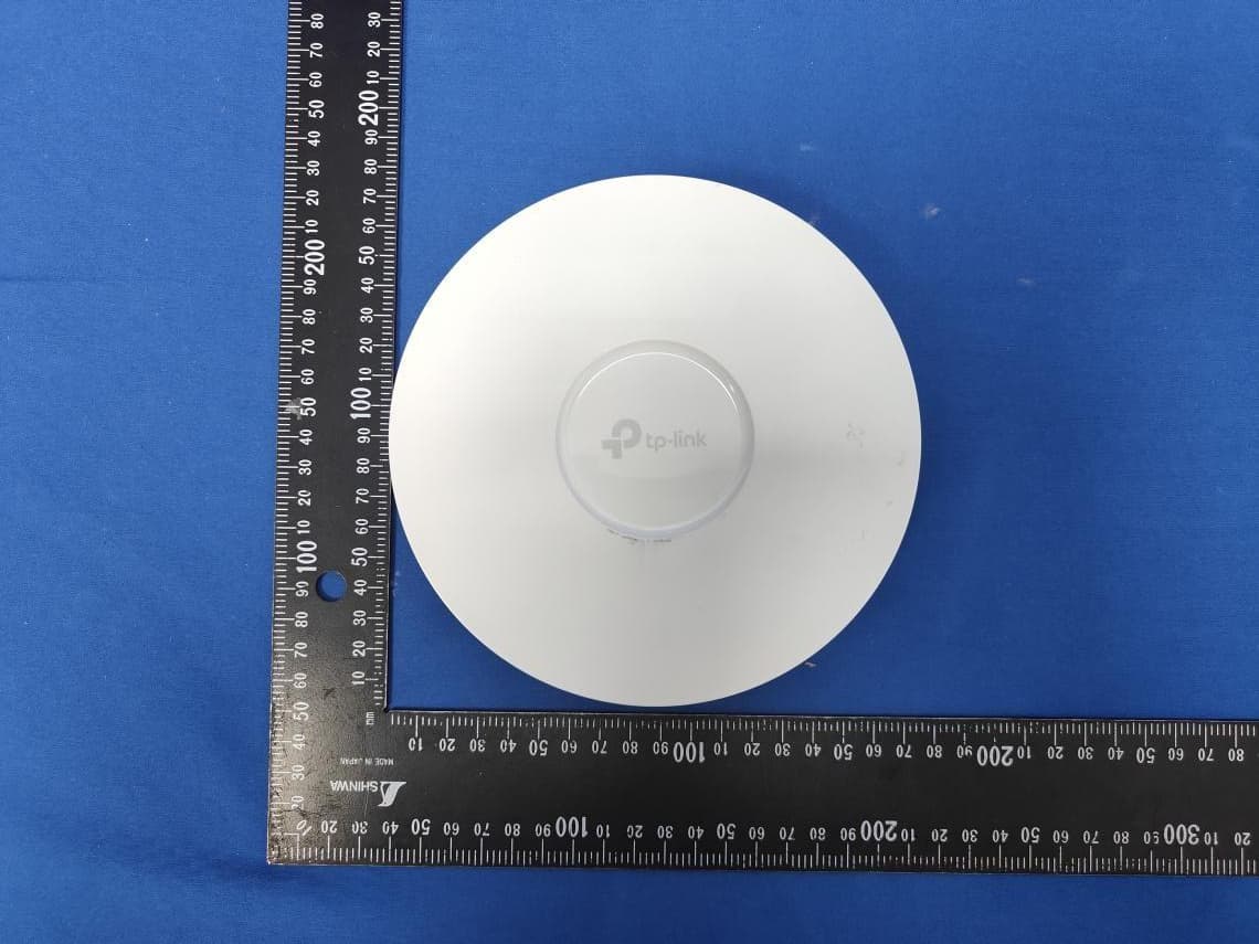
Click to zoom
Application Details
- Equipment Class
- DTS - Digital Transmission System
- Date of Grant
- Dec 11, 2025
- Application Purpose
- Original Equipment
- Equipment Note
- AX3000 Ceiling Mount Wi-Fi 6 Access Point
- Frequency Range
- 2412.00000000 - 2462.00000000
- Company
- TP-Link Corporation Limited
- Country
- Hong Kong
Documents & Files
Document Text
Text extracted from the exhibit documents filed with the FCC. Open a document above to read the original.
Users Manual
Quick Installation Guide Wireless Access Point Setup with videos Visit https://www.tp-link.com/support/setup-video/ or scan the QR code to search for the setup video of your product model. Note: For simplicity, we will take EAP650 V1 for example throughout the Guide. The image may differ from the actual product. Hardware Overview 1 On: Working normally/Initializing. Off: Working abnormally/Power off/LED is turned off. Flashing: Initialization: The LED flashes twice after initialization is completed. Upgrade: The LED flashes once per second while upgrading. Reset: The LED flashes quickly during the reset. The EAP will then reboot. Isolated: The LED flashes slowly. The EAP is in the isolated state. Locate: When the Locate feature is activated in the Omada controller, the LED flashes quickly to locate and identify the device. The LED will flash for 10 minutes, or you can disable the feature manually to stop it flashing. LED Indicator RESET With the device powered on, press and hold the button for about 5 seconds until the LED flashes quickly. Then release the button. The device will restore to factory default settings. The port is used to connect to a router or a switch to transmit data, or to a PSE (Power Sourcing Equipment), such as a PoE switch, for both data transmission and Power over Ethernet (PoE) through Ethernet cable. The port supports transmission speed of 10/100/1000 Mbps. Ethernet Port: ETH (PoE) Plug one end of the provided power adapter to this port and the other end to a standard electrical wall outlet to power the EAP. Please use the power adapter provided in the package. Power Port M3×20 Self-tapping Screws (Qty.4) M3×28 Plastic Wall Anchors (Qty.4) 1 Remove the ceiling tile. Note: Make sure that the ceiling tile is larger than the EAP. Wing Nuts (Qty.4)Washers (Qty.4)M3×30 Pan-head Screws (Qty.4) The EAP can be mounted to the ceiling, the wall, or in a junction box, using the screws in the package. Choose the appropriate mounting and installation steps below. Note: This product requires heat dissipation through the metal bracket during use, please be careful not to touch the metal bracket in the heat dissipation. Hardware Installation 2 2 Insert the plastic wall anchors into the 6 mm diameter holes. 4 Connect the Ethernet cable to the Ethernet port on the EAP. Front Panel Rear Panel Option 2: Wall Mounting Option 1: Ceiling Mounting Option 2: Wall Mounting 5 Connect the Ethernet cable to the Ethernet port. Please pay attention to the triangle sign. Attach the EAP to the mounting bracket, then rotate it until it locks into place, as shown on the left. 2 Place the mounting bracket in the center of the ceiling tile. Mark four positions for the screw holes and a location for the Ethernet cable hole. Drill four 4 mm (5/32 in) diameter holes for the screws and a 25 mm (63/64 in) diameter hole for the Ethernet cable at the marked positions. Drill Hole for Ethernet cable X4 3 Secure the mounting bracket to the ceiling tile using four M3x30 pan-head screws, washers, and wing nuts, as shown on the left. 5 Attach the EAP to the mounting bracket by rotating it until it locks into place, as shown on the left. Option 3: Junction Box Mounting 4 Feed the Ethernet cable through the hole and set the ceiling tile back into place. Prepare the cables and the junction box in advance. Ensure that the mounting holes align to your junction box. *Compatible wall junctions: Route the cables through the square cable hole on the mounting bracket, and secure the mounting bracket to the junction box using screws. Then follow Step 4 and Step 5 of Option 2 to complete the installation. 3 Secure the mounting bracket to the wall by driving the self-tapping screws into the anchors. Make sure that the shoulders of the mounting bracket are on the outside. 1 If your Ethernet cable feeds through the wall, position the mounting bracket below the cable hole. Mark four positions for the screw holes and drill four 6 mm (15/64 in) diameter holes at the marked positions. X4 Option 1: Ceiling Mounting Option 3: Junction Box Mounting ©2022 TP-Link 7106509468 REV1.0.0 The products of TP-Link partly contain software code developed by third parties, including software code subject to the GNU General Public License (“GPL”). As applicable, the terms of the GPL and any information on obtaining access to the respective GPL Code used in TP-Link products are available to you in GPL-Code-Centre under (https://www.tp-link.com/en/support/gpl/). The respective programs are distributed WITHOUT ANY WARRANTY and are subject to the copyrights of one or more authors. For details, see the GPL Code and other terms of the GPL. Choose from the following methods to set up your EAPs: The EAP can be powered via a power adapter or a PSE device (such as a PoE switch) which complies with LPS or PS2 standard. Method 1: Standalone Mode Option1: Via PoE Switch (Compliant with 802.3at) Option2: Via Power Adapter Note: Via Omada App Via Omada App 1. Connect wirelessly by using the default SSID (format: TP-Link_2.4GHz/5GHz_XXXXXX) printed on the label at the bottom of the product. 2. Launch a web browser and enter http://tplinkeap.net in the address bar. Use admin for both Username and Password to log in. 3. Set up a new Username and Password for secure management purpose. Modify the wireless parameters and reconnect your wireless devices to the new wireless network. To configure other EAPs, connect your device to the EAP by the coresponding default SSID and repeat the steps listed above. You can configure some basic functions in Standalone Mode. If you want to configure advanced functions, use Controller Mode. 1. Download the TP-Link Omada App on your mobile device. It can be downloaded from App Store or Google Play: 2. Connect your mobile device to the EAP by using the default SSID (format: TP-Link_2.4GHz/5GHz_XXXXXX) printed on the label at the bottom of the product. 3. Open the Omada App, and wait for the EAP to appear on the Standalone APs page. T…
Text truncated - open the document above for the full version.
Internal Photos
Report No.: 2509TW0109-UI 1 of 5 Internal Photograph (1) EUT Photo (2) EUT Photo Report No.: 2509TW0109-UI 2 of 5 (3) EUT Photo (4) EUT Photo Report No.: 2509TW0109-UI 3 of 5 (5) EUT Photo (6) EUT Photo Report No.: 2509TW0109-UI 4 of 5 (7) EUT Photo (8) EUT Photo Report No.: 2509TW0109-UI 5 of 5 (9) EUT Photo (10) EUT Photo
Test Setup Photos
Report No.: 2509TW0109-UT 1 of 4 RF Test Photograph Description: Front View of Conducted Emission Test Setup Description: Back View of Conducted Emission Test Setup Report No.: 2509TW0109-UT 2 of 4 Description: Radiated Emission Test Setup for below 1GHz Description: Radiated Emission Test Setup for above 1GHz Report No.: 2509TW0109-UT 3 of 4 Description: Radiated Emission Test Setup for 18GHz~40GHz Description: Conducted Measurement Test Setup Report No.: 2509TW0109-UT 4 of 4 Description: DFS Test Setup
Test Report
Report No.: 2112TW0008-U1 FCC ID: 2AXJ4EAP650 Page Number: 102 of 199 The Result of Radiated Emission below 1GHz: EUT AX3000 Ceiling Mount Wi-Fi 6 Access Point Date of Test 2021-03-01 Factor VULB 9162 Temp. / Humidity 25°C /54% Polarity Horizontal Site / Test Engineer AC1 / Jay Test Mode Transmit by 802.11b at channel 2437MHz Test Voltage AC 120V/60Hz No Frequency (MHz) Reading (dBuV) C.F (dB/m) Measurement (dBuV/m) Margin (dB) Limit (dBuV/m) Remark (QP/PK/AV) 1 49.620 -3.48 22.03 18.55 -21.45 40.00 Peak 2 154.821 11.43 16.14 27.57 -15.93 43.50 Peak 3 168.709 8.62 16.61 25.23 -18.27 43.50 Peak 4 281.995 0.43 21.08 21.51 -24.49 46.00 Peak 5 500.301 1.74 26.22 27.96 -18.04 46.00 Peak 6 * 737.071 0.32 29.91 30.23 -15.77 46.00 Peak Note: 1. " *", means this data is the worst emission level. 2. C.F (Correction Factor) = Antenna Factor (dB/m) + Cable Loss (dB). 3. Measurement(dBuV/m) = Reading(dBuV) + C.F (Correction Factor). 4.The emission levels of other frequencies are very lower than the limit and not show in test report. 5.The amplitude of Radiated emissions (the test frequency range: 9kHz ~ 30MHz, 18GHz ~ 25GHz), is that proximity to ambient noise, which also are attenuated more than 20 dB below the permissible value. Therefore, the data is not presented in the report. Report No.: 2112TW0008-U1 FCC ID: 2AXJ4EAP650 Page Number: 103 of 199 EUT AX3000 Ceiling Mount Wi-Fi 6 Access Point Date of Test 2021-03-01 Factor VULB 9162 Temp. / Humidity 25°C /54% Polarity Vertical Site / Test Engineer AC1 / Jay Test Mode Transmit by 802.11b at channel 2437MHz Test Voltage AC 120V/60Hz No Frequency (MHz) Reading (dBuV) C.F (dB/m) Measurement (dBuV/m) Margin (dB) Limit (dBuV/m) Remark (QP/PK/AV) 1 36.960 5.51 20.00 25.51 -14.49 40.00 Peak 2 * 60.386 7.97 20.08 28.05 -11.95 40.00 Peak 3 87.725 9.81 16.31 26.12 -13.88 40.00 Peak 4 109.989 8.85 18.71 27.56 -15.94 43.50 Peak 5 154.008 15.42 16.11 31.53 -11.97 43.50 Peak 6 612.064 -0.45 28.00 27.54 -18.46 46.00 Peak Note: 1. " *", means this data is the worst emission level. 2. C.F (Correction Factor) = Antenna Factor (dB/m) + Cable Loss (dB). 3. Measurement(dBuV/m) = Reading(dBuV) + C.F (Correction Factor). 4.The emission levels of other frequencies are very lower than the limit and not show in test report. 5.The amplitude of Radiated emissions (the test frequency range: 9kHz ~ 30MHz, 18GHz ~ 25GHz), is that proximity to ambient noise, which also are attenuated more than 20 dB below the permissible value. Therefore, the data is not presented in the report. Report No.: 2112TW0008-U1 FCC ID: 2AXJ4EAP650 Page Number: 104 of 199 7.7. Radiated Restricted Band Edge Measurement 7.7.1.Test Limit For 15.205 requirement: Radiated emissions which fall in the restricted bands, as defined in Section 15.205(a) of FCC part 15, must also comply with the radiated emission limits specified in Section 15.209(a). Frequency (MHz) Frequency (MHz) Frequency (MHz) Frequency (GHz) 0.090 - 0.110 16.42 - 16.423 399.9 - 410 4.5 - 5.15 1 0.495 - 0.505 16.69475 - 16.69525 608 - 614 5.35 - 5.46 2.1735 - 2.1905 16.80425 - 16.80475 960 - 1240 7.25 - 7.75 4.125 - 4.128 25.5 - 25.67 1300 - 1427 8.025 - 8.5 4.17725 - 4.17775 37.5 - 38.25 1435 - 1626.5 9.0 - 9.2 4.20725 - 4.20775 73 - 74.6 1645.5 - 1646.5 9.3 - 9.5 6.215 - 6.218 74.8 - 75.2 1660 - 1710 10.6 - 12.7 6.26775 - 6.26825 108 - 121.94 1718.8 - 1722.2 13.25 - 13.4 6.31175 - 6.31225 123 - 138 2200 - 2300 14.47 - 14.5 8.291 - 8.294 149.9 - 150.05 2310 - 2390 15.35 - 16.2 8.362 - 8.366 156.52475 - 156.52525 2483.5 - 2500 17.7 - 21.4 8.37625 - 8.38675 156.7 - 156.9 2690 - 2900 22.01 - 23.12 8.41425 - 8.41475 162.0125 - 167.17 3260 - 3267 23.6 - 24.0 12.29 - 12.293 167.72 - 173.2 3332 - 3339 31.2 - 31.8 12.51975 - 12.52025 240 - 285 3345.8 - 3358 36.43 - 36.5 12.57675 - 12.57725 322 - 335.4 3600 - 4400 ( 2 ) 13.36 - 13.41 -- -- -- Report No.: 2112TW0008-U1 FCC ID: 2AXJ4EAP650 Page Number: 105 of 199 All out of band emissions appearing in a restricted band as specified in Section 15.205 of the Title 47CFR must not exceed the limits shown in Table per Section 15.209. FCC Part 15 Subpart C Paragraph 15.209 Limits Frequency [MHz] Field Strength [uV/m] Measured Distance [Meters] 0.009 - 0.490 2400/F (kHz) 300 0.490 - 1.705 24000/F (kHz) 30 1.705 - 30 30 30 30 - 88 100 3 88 - 216 150 3 216 - 960 200 3 Above 960 500 3 7.7.2.Test Procedure Used ANSI C63.10 Section 6.3 (General Requirements) ANSI C63.10 Section 6.6 (Standard test method above 1GHz) 7.7.3.Test Setting Peak Field Strength Measurements 1. Analyzer center frequency was set to the frequency of the radiated spurious emission of interest 2. RBW = 1MHz 3. VBW = 3MHz 4. Detector = peak 5. Sweep time = auto couple 6. Trace mode = max hold 7. Trace was allowed to stabilize Report No.: 2112TW0008-U1 FCC ID: 2AXJ4EAP650 Page Number: 106 of 199 Average Measurements above 1GHz (Method VB) 1. Analyzer center frequency was set to the frequency of the radiated spurious emission of interest 2. RBW = 1MHz 3. VBW; If the EUT is configured to transmit with duty cycle ≥ 98%, set VBW = 10 Hz. If the EUT duty cycle is < 98%, set VBW ≥ 1/T. T is the minimum transmission duration. 4. Detector = Peak 5. Sweep time = auto 6. Trace mode = max hold 7. Trace was allowed to stabilize 7.7.4.Test Setup Report No.: 2112TW0008-U1 FCC ID: 2AXJ4EAP650 Page Number: 107 of 199 7.7.5.Test Result EUT AX3000 Ceiling Mount Wi-Fi 6 Access Point Date of Test 2022-01-21 Factor BBHA 9120D (1GHz~18GHz) Temp. / Humidity 22.6°C/36.4% Polarity Horizontal Site / Test Engineer AC1 / Jay Test Mode Transmit by 802.11b at channel 2412MHz Test Voltage 120V/60Hz No Frequency (MHz) Reading (dBuV) C.F (dB/m) Measurement (dBuV/m) Margin (dB) Limit (dBuV/m) Remark (QP/PK/AV) 1 2387.000 30.25 32.21 62.45 -11.55 74.00 Peak 2 2390.000 26.32 32.22 58.54 -15.46 74.00 Peak 3 * 2414.720 78.59 32.32 110.91 N/A N/A Peak Note: 1. " *", means this data is the worst emission level. 2. C.F (Correction Factor) = Antenna Factor (dB/m)+ Cable Loss (dB) 3. Meas…
Text truncated - open the document above for the full version.
Test Report
Report No.: 2112TW0008-U1 FCC ID: 2AXJ4EAP650 Page Number: 54 of 199 802.11g Out-of-Band Emissions – Ant 1 Channel 11 (2462MHz) Reference Level High Band Edge Spurious Emission Report No.: 2112TW0008-U1 FCC ID: 2AXJ4EAP650 Page Number: 55 of 199 802.11n-HT20 Out-of-Band Emissions – Ant 1 Channel 01 (2412MHz) Reference Level Low Band Edge Spurious Emission Channel 06 (2437MHz) Reference Level Spurious Emission Report No.: 2112TW0008-U1 FCC ID: 2AXJ4EAP650 Page Number: 56 of 199 802.11n-HT20 Out-of-Band Emissions – Ant 1 Channel 11 (2462MHz) Reference Level High Band Edge Spurious Emission Report No.: 2112TW0008-U1 FCC ID: 2AXJ4EAP650 Page Number: 57 of 199 802.11n-HT40 Out-of-Band Emissions – Ant 1 Channel 03 (2422MHz) Reference Level Low Band Edge Spurious Emission Channel 06 (2437MHz) Reference Level Spurious Emission Report No.: 2112TW0008-U1 FCC ID: 2AXJ4EAP650 Page Number: 58 of 199 802.11n-HT40 Out-of-Band Emissions – Ant 1 Channel 09 (2452MHz) Reference Level High Band Edge Spurious Emission Report No.: 2112TW0008-U1 FCC ID: 2AXJ4EAP650 Page Number: 59 of 199 802.11ax-HE20 Out-of-Band Emissions – Ant 1 Channel 01 (2412MHz) Reference Level Low Band Edge Spurious Emission Channel 06 (2437MHz) Reference Level Spurious Emission Report No.: 2112TW0008-U1 FCC ID: 2AXJ4EAP650 Page Number: 60 of 199 802.11ax-HE20 Out-of-Band Emissions – Ant 1 Channel 11 (2462MHz) Reference Level High Band Edge Spurious Emission Report No.: 2112TW0008-U1 FCC ID: 2AXJ4EAP650 Page Number: 61 of 199 802.11ax-HE40 Out-of-Band Emissions – Ant 1 Channel 03 (2422MHz) Reference Level Low Band Edge Spurious Emission Channel 06 (2437MHz) Reference Level Spurious Emission Report No.: 2112TW0008-U1 FCC ID: 2AXJ4EAP650 Page Number: 62 of 199 802.11ax-HE40 Out-of-Band Emissions – Ant 1 Channel 09 (2452MHz) Reference Level High Band Edge Spurious Emission Report No.: 2112TW0008-U1 FCC ID: 2AXJ4EAP650 Page Number: 63 of 199 7.6. Radiated Spurious Emission Measurement 7.6.1.Test Limit All out of band emissions appearing in a restricted band as specified in Section 15.205 of the Title 47CFR must not exceed the limits shown in Table per Section 15.209. FCC Part 15 Subpart C Paragraph 15.209 Frequency [MHz] Field Strength [Uv/m] Measured Distance [Meters] 0.009 - 0.490 2400/F (kHz) 300 0.490 - 1.705 24000/F (kHz) 30 1.705 - 30 30 30 30 - 88 100 3 88 - 216 150 3 216 - 960 200 3 Above 960 500 3 7.6.2.Test Procedure Used ANSI C63.10 - 2013 - Section 11.11 & 11.12 ANSI C63.10 - 2013 - Section 6.3 (General Requirements) ANSI C63.10 - 2013 - Section 6.4 (Standard test method below 30MHz) ANSI C63.10 - 2013 - Section 6.5 (Standard test method above 30MHz to 1GHz) ANSI C63.10 - 2013 - Section 6.6 (Standard test method above 1GHz) 7.6.3.Test Setting Table 1 - RBW as a function of frequency Frequency RBW 9 ~ 150 kHz 200 ~ 300 Hz 0.15 ~ 30 MHz 9 ~ 10 kHz 30 ~ 1000 MHz 100 ~ 120 kHz > 1000MHz 1MHz Report No.: 2112TW0008-U1 FCC ID: 2AXJ4EAP650 Page Number: 64 of 199 Quasi-Peak Measurements below 1GHz 1. Analyzer center frequency was set to the frequency of the radiated spurious emission of interest 2. Span was set greater than 1MHz 3. RBW = as specified in Table 1 4. Detector = CISPR quasi-peak 5. Sweep time = auto couple 6. Trace was allowed to stabilize Peak Measurements above 1GHz 1. Analyzer center frequency was set to the frequency of the radiated spurious emission of interest 2. RBW = 1MHz 3. VBW = 3MHz 4. Detector = peak 5. Sweep time = auto couple 6. Trace mode = max hold 7. Trace was allowed to stabilize Average Measurements above 1GHz (Method VB) 1. Analyzer center frequency was set to the frequency of the radiated spurious emission of interest 2. RBW = 1MHz 3. VBW; If the EUT is configured to transmit with duty cycle ≥ 98%, set VBW = 10 Hz. If the EUT duty cycle is < 98%, set VBW ≥ 1/T. T is the minimum transmission duration. 4. Detector = Peak 5. Sweep time = auto 6. Trace mode = max hold 7. Trace was allowed to stabilize Report No.: 2112TW0008-U1 FCC ID: 2AXJ4EAP650 Page Number: 65 of 199 7.6.4.Test Setup Below 1GHz Test Setup: Above 1GHz Test Setup: Report No.: 2112TW0008-U1 FCC ID: 2AXJ4EAP650 Page Number: 66 of 199 7.6.5.Test Result EUT AX3000 Ceiling Mount Wi-Fi 6 Access Point Date of Test 2022-01-29 Factor BBHA 9120D (1GHz~18GHz) Temp. / Humidity 19.5°C /35.8% Polarity Horizontal Site / Test Engineer AC1 / Jay Test Mode Transmit by 802.11b at Channel 2412MHz Test Voltage 120V/60Hz No Frequency (MHz) Reading (dBm) C.F (dB) Measurement (dBm) Margin (dB) Limit (dBm) Remark (QP/PK/AV) 1 9092.000 33.65 15.03 48.68 -25.32 74.00 Peak 2 * 11548.500 31.02 19.94 50.96 -23.04 74.00 Peak 3 12186.000 32.22 18.73 50.95 -23.05 74.00 Peak Note: 1. " *", means this data is the worst emission level. 2. C.F (Correction Factor) = Antenna Factor (dB)+ Cable Loss (dB)– Preamplifier(dB). 3. Measurement(dBm) = Reading(dBm) + C.F (Correction Factor). 4.The emission levels of other frequencies are very lower than the limit and not show in test report. Report No.: 2112TW0008-U1 FCC ID: 2AXJ4EAP650 Page Number: 67 of 199 EUT AX3000 Ceiling Mount Wi-Fi 6 Access Point Date of Test 2022-01-29 Factor BBHA 9120D (1GHz~18GHz) Temp. / Humidity 19.5°C /35.8% Polarity Vertical Site / Test Engineer AC1 / Jay Test Mode Transmit by 802.11b at Channel 2412MHz Test Voltage 120V/60Hz No Frequency (MHz) Reading (dBm) C.F (dB) Measurement (dBm) Margin (dB) Limit (dBm) Remark (QP/PK/AV) 1 7468.500 33.23 12.88 46.11 -27.89 74.00 Peak 2 11174.500 30.73 19.55 50.28 -23.72 74.00 Peak 3 * 11421.000 30.77 19.93 50.70 -23.30 74.00 Peak Note: 1. " *", means this data is the worst emission level. 2. C.F (Correction Factor) = Antenna Factor (dB)+ Cable Loss (dB)– Preamplifier(dB). 3. Measurement(dBm) = Reading(dBm) + C.F (Correction Factor). 4.The emission levels of other frequencies are very lower than the limit and not show in test report. Report No.: 2112TW0008-U1 FCC ID: 2AXJ4EAP650 Page Number: 68 of 199 EUT AX3000 Ceiling Mount Wi-Fi 6 Access Point Date of Test 2022-01-2…
Text truncated - open the document above for the full version.
Test Report
Report No.: 2112TW0008-U1 FCC ID: 2AXJ4EAP650 Page Number: 45 of 199 802.11n-HT40 Out-of-Band Emissions – Ant 0 Channel 03 (2422MHz) Reference Level Low Band Edge Spurious Emission Channel 06 (2437MHz) Reference Level Spurious Emission Report No.: 2112TW0008-U1 FCC ID: 2AXJ4EAP650 Page Number: 46 of 199 802.11n-HT40 Out-of-Band Emissions – Ant 0 Channel 09 (2452MHz) Reference Level High Band Edge Spurious Emission Report No.: 2112TW0008-U1 FCC ID: 2AXJ4EAP650 Page Number: 47 of 199 802.11ax-HE20 Out-of-Band Emissions – Ant 0 Channel 01 (2412MHz) Reference Level Low Band Edge Spurious Emission Channel 06 (2437MHz) Reference Level Spurious Emission Report No.: 2112TW0008-U1 FCC ID: 2AXJ4EAP650 Page Number: 48 of 199 802.11ax-HE20 Out-of-Band Emissions – Ant 0 Channel 11 (2462MHz) Reference Level High Band Edge Spurious Emission Report No.: 2112TW0008-U1 FCC ID: 2AXJ4EAP650 Page Number: 49 of 199 802.11ax-HE40 Out-of-Band Emissions – Ant 0 Channel 03 (2422MHz) Reference Level Low Band Edge Spurious Emission Channel 06 (2437MHz) Reference Level Spurious Emission Report No.: 2112TW0008-U1 FCC ID: 2AXJ4EAP650 Page Number: 50 of 199 802.11ax-HE40 Out-of-Band Emissions – Ant 0 Channel 09 (2452MHz) Reference Level High Band Edge Spurious Emission Report No.: 2112TW0008-U1 FCC ID: 2AXJ4EAP650 Page Number: 51 of 199 802.11b Out-of-Band Emissions – Ant 1 Channel 01 (2412MHz) Reference Level Low Band Edge Spurious Emission Channel 06 (2437MHz) Reference Level Spurious Emission Report No.: 2112TW0008-U1 FCC ID: 2AXJ4EAP650 Page Number: 52 of 199 802.11b Out-of-Band Emissions – Ant 1 Channel 11 (2462MHz) Reference Level High Band Edge Spurious Emission Report No.: 2112TW0008-U1 FCC ID: 2AXJ4EAP650 Page Number: 53 of 199 802.11g Out-of-Band Emissions – Ant 1 Channel 01 (2412MHz) Reference Level Low Band Edge Spurious Emission Channel 06 (2437MHz) Reference Level Spurious Emission
Test Report
Report No.: 2112TW0008-U1 FCC ID: 2AXJ4EAP650 Page Number: 34 of 199 802.11n-HT20 – AVGPSD -Ant 1 Channel 01 (2412MHz) Channel 06 (2437MHz) Channel 11 (2462MHz) 802.11n-HT40 – AVGPSD -Ant 1 Channel 03 (2422MHz) Channel 06 (2437MHz) Channel 09 (2452MHz) Report No.: 2112TW0008-U1 FCC ID: 2AXJ4EAP650 Page Number: 35 of 199 802.11ax-HE20 – AVGPSD -Ant 1 Channel 01 (2412MHz) Channel 06 (2437MHz) Channel 11 (2462MHz) 802.11ax-HE40 – AVGPSD -Ant 1 Channel 03 (2422MHz) Channel 06 (2437MHz) Channel 09 (2452MHz) Report No.: 2112TW0008-U1 FCC ID: 2AXJ4EAP650 Page Number: 36 of 199 7.5. Conducted Band Edge and Out-of-Band Emissions 7.5.1.Test Limit The limit for out-of-band spurious emissions at the band edge is 30dB below the fundamental emission level, as determined from the in-band power measurement of the DTS channel performed in a 100 kHz bandwidth per the PSD procedure. 7.5.2.Test Procedure Used ANSI C63.10 Section 11.11 7.5.3.Test Setting Reference level measurement 1. Set instrument center frequency to DTS channel center frequency 2. Set the span to ≥ 1.5 times the DTS bandwidth 3. Set the RBW = 100 kHz 4. Set the VBW ≥ 3 x RBW 5. Detector = peak 6. Sweep time = auto couple 7. Trace mode = max hold 8. Allow trace to fully stabilize Emission level measurement 1. Set the center frequency and span to encompass frequency range to be measured 2. RBW = 100KHz 3. VBW = 300KHz 4. Detector = Peak 5. Trace mode = max hold 6. Sweep time = auto couple 7. The trace was allowed to stabilize Report No.: 2112TW0008-U1 FCC ID: 2AXJ4EAP650 Page Number: 37 of 199 7.5.4.Test Setup Report No.: 2112TW0008-U1 FCC ID: 2AXJ4EAP650 Page Number: 38 of 199 7.5.5.Test Result Product AX3000 Ceiling Mount Wi-Fi 6 Access Point Temperature 23°C Test Engineer Eric Lin Relative Humidity 54% Te s t S i t e SR2 Test Date 2022/02/07~2022/02/08 Test Mode Data Rate / MCS Channel No. Frequency (MHz) Limit (dBc) Result 802.11b 1Mbps 01 2412 30 Pass 802.11b 1Mbps 06 2437 30 Pass 802.11b 1Mbps 11 2462 30 Pass 802.11g 6Mbps 01 2412 30 Pass 802.11g 6Mbps 06 2437 30 Pass 802.11g 6Mbps 11 2462 30 Pass 802.11n-HT20 MCS0 01 2412 30 Pass 802.11n-HT20 MCS0 06 2437 30 Pass 802.11n-HT20 MCS0 11 2462 30 Pass 802.11n-HT40 MCS0 03 2422 30 Pass 802.11n-HT40 MCS0 06 2437 30 Pass 802.11n-HT40 MCS0 09 2452 30 Pass 802.11ax-HE20 MCS0 01 2412 30 Pass 802.11ax-HE20 MCS0 06 2437 30 Pass 802.11ax-HE20 MCS0 11 2462 30 Pass 802.11ax-HE40 MCS0 03 2422 30 Pass 802.11ax-HE40 MCS0 06 2437 30 Pass 802.11ax-HE40 MCS0 09 2452 30 Pass Report No.: 2112TW0008-U1 FCC ID: 2AXJ4EAP650 Page Number: 39 of 199 802.11b Out-of-Band Emissions – Ant 0 Channel 01 (2412MHz) Reference Level Low Band Edge Spurious Emission Channel 06 (2437MHz) Reference Level Spurious Emission Report No.: 2112TW0008-U1 FCC ID: 2AXJ4EAP650 Page Number: 40 of 199 802.11b Out-of-Band Emissions – Ant 0 Channel 11 (2462MHz) Reference Level High Band Edge Spurious Emission Report No.: 2112TW0008-U1 FCC ID: 2AXJ4EAP650 Page Number: 41 of 199 802.11g Out-of-Band Emissions – Ant 0 Channel 01 (2412MHz) Reference Level Low Band Edge Spurious Emission Channel 06 (2437MHz) Reference Level Spurious Emission Report No.: 2112TW0008-U1 FCC ID: 2AXJ4EAP650 Page Number: 42 of 199 802.11g Out-of-Band Emissions – Ant 0 Channel 11 (2462MHz) Reference Level High Band Edge Spurious Emission Report No.: 2112TW0008-U1 FCC ID: 2AXJ4EAP650 Page Number: 43 of 199 802.11n-HT20 Out-of-Band Emissions – Ant 0 Channel 01 (2412MHz) Reference Level Low Band Edge Spurious Emission Channel 06 (2437MHz) Reference Level Spurious Emission Report No.: 2112TW0008-U1 FCC ID: 2AXJ4EAP650 Page Number: 44 of 199 802.11n-HT20 Out-of-Band Emissions – Ant 0 Channel 11 (2462MHz) Reference Level High Band Edge Spurious Emission
Test Report
Report No.: 2112TW0008-U1 FCC ID: 2AXJ4EAP650 Page Number: 23 of 199 802.11ax-HE20 6dB Bandwidth Channel 01 (2412MHz) Channel 06 (2437MHz) Channel 11 (2462MHz) 802.11ax-HE40 6dB Bandwidth Channel 03 (2422MHz) Channel 06 (2437MHz) Channel 09 (2452MHz) Report No.: 2112TW0008-U1 FCC ID: 2AXJ4EAP650 Page Number: 24 of 199 7.3. Output Power Measurement 7.3.1.Test Limit The maximum output power shall be less 1 Watt (30dBm). The conducted output power limit specified in paragraph FCC Part 15.247(b) of this section is based on the use of antennas with directional gains that do not exceed 6 dBi. If transmitting antennas of directional gain greater than 6 dBi are used, the conducted output power from the intentional radiator shall be reduced below the stated values in paragraphs FCC Part 15.247(b)(3) of this section, as appropriate, by the amount in dB that the directional gain of the antenna exceeds 6 dBi. 7.3.2.Test Procedure Used ANSI C63.10 Section 11.9.2.3.2 7.3.3.Test Setting Average Power Measurement Average power measurements were performed only when the EUT was transmitting at its maximum power control level using a broadband power meter with a pulse sensor. The power meter implemented triggering and gating capabilities which were set up such that power measurements were recorded only during the ON time of the transmitter. 7.3.4.Test Setup Report No.: 2112TW0008-U1 FCC ID: 2AXJ4EAP650 Page Number: 25 of 199 7.3.5.Test Result Product AX3000 Ceiling Mount Wi-Fi 6 Access Point Temperature 23°C Test Engineer Eric Lin Relative Humidity 54% Te s t S i t e SR2 Test Date 2022/01/03 ~ 2022/02/08 Test Mode Data Rate / MCS Channel No. Freq. (MHz) Average Power (dBm) Total Average Power (dBm) CDD Limit (dBm) Beam-forming Limit (dBm) Result Ant 0 Ant 1 CDD Mode 11b 1Mbps 01 2412 18.35 18.44 21.41 ≤ 30.00 -- Pass 11b 1Mbps 02 2417 19.62 19.57 22.61 ≤ 30.00 -- Pass 11b 1Mbps 03 2422 23.46 23.38 26.43 ≤ 30.00 -- Pass 11b 1Mbps 06 2437 23.45 23.10 26.29 ≤ 30.00 -- Pass 11b 1Mbps 11 2462 20.97 20.94 23.97 ≤ 30.00 -- Pass 11g 6Mbps 01 2412 17.90 17.81 20.87 ≤ 30.00 -- Pass 11g 6Mbps 02 2417 20.44 20.40 23.43 ≤ 30.00 -- Pass 11g 6Mbps 06 2437 23.04 22.82 25.94 ≤ 30.00 -- Pass 11g 6Mbps 10 2457 20.51 20.44 23.49 ≤ 30.00 -- Pass 11g 6Mbps 11 2462 18.01 17.86 20.95 ≤ 30.00 -- Pass 11n-HT20 MCS0 01 2412 17.36 17.40 20.39 ≤ 30.00 -- Pass 11n-HT20 MCS0 02 2417 19.18 19.05 22.13 ≤ 30.00 -- Pass 11n-HT20 MCS0 06 2437 22.10 21.75 24.94 ≤ 30.00 -- Pass 11n-HT20 MCS0 10 2457 20.48 20.31 23.41 ≤ 30.00 -- Pass 11n-HT20 MCS0 11 2462 16.47 16.27 19.38 ≤ 30.00 -- Pass 11n-HT40 MCS0 03 2422 16.44 16.68 19.57 ≤ 30.00 -- Pass 11n-HT40 MCS0 06 2437 18.18 17.90 21.05 ≤ 30.00 -- Pass 11n-HT40 MCS0 09 2452 15.92 15.73 18.84 ≤ 30.00 -- Pass CDD & Beamforming Mode 11ax-HE20 MCS0 01 2412 17.02 17.22 20.13 ≤ 30.00 ≤ 29.19 Pass 11ax-HE20 MCS0 02 2417 19.21 18.92 22.08 ≤ 30.00 ≤ 29.19 Pass 11ax-HE20 MCS0 03 2422 21.12 21.10 24.12 ≤ 30.00 ≤ 29.19 Pass 11ax-HE20 MCS0 06 2437 23.32 23.77 26.56 ≤ 30.00 ≤ 29.19 Pass 11ax-HE20 MCS0 09 2452 21.83 21.82 24.84 ≤ 30.00 ≤ 29.19 Pass 11ax-HE20 MCS0 10 2457 19.17 19.03 22.11 ≤ 30.00 ≤ 29.19 Pass 11ax-HE20 MCS0 11 2462 17.12 17.21 20.18 ≤ 30.00 ≤ 29.19 Pass Report No.: 2112TW0008-U1 FCC ID: 2AXJ4EAP650 Page Number: 26 of 199 Test Mode Data Rate / MCS Channel No. Freq. (MHz) Average Power (dBm) Total Average Power (dBm) CDD Limit (dBm) Beam-forming Limit (dBm) Result 11ax-HE40 MCS0 03 2422 17.46 17.41 20.45 ≤ 30.00 ≤ 29.19 Pass 11ax-HE40 MCS0 06 2437 18.36 18.68 21.53 ≤ 30.00 ≤ 29.19 Pass 11ax-HE40 MCS0 09 2452 16.42 16.16 19.30 ≤ 30.00 ≤ 29.19 Pass Note 1: Total Average Power (dBm) = 10*log {10 (Ant 0 Average Power /10) +10 (Ant 1 Average Power /10) }. Note 2: Beamforming Power Limit (dBm) = 30-(6.81-6) = 29.19dBm Report No.: 2112TW0008-U1 FCC ID: 2AXJ4EAP650 Page Number: 27 of 199 7.4. Power Spectral Density Measurement 7.4.1.Test Limit The maximum permissible power spectral density is 8dBm in any 3 kHz band. The same method of determining the conducted output power shall be used to determine the power spectral density. 7.4.2.Test Procedure Used ANSI C63.10 Section 11.10.5 7.4.3.Test Setting 1. Measure the duty cycle (x) of the transmitter output signal. 2. Set instrument center frequency to DTS channel center frequency. 3. Set span to at least 1.5 times the OBW. 4. RBW = 10 kHz. 5. VBW = 30 kHz. 6. Detector = RMS. 7. Ensure that the number of measurement points in the sweep ≥ 2 x span/RBW. 8. Sweep time = auto couple. 9. Don’t use sweep triggering. Allow sweep to “free run”. 10. Employ trace averaging (RMS) mode over a minimum of 100 traces. 11. Use the peak marker function to determine the maximum amplitude level. 12. Add 10 log (1/x), where x is the duty cycle measured in step (a, to the measured PSD to compute the average PSD during the actual transmission time. Report No.: 2112TW0008-U1 FCC ID: 2AXJ4EAP650 Page Number: 28 of 199 7.4.4.Test Setup Report No.: 2112TW0008-U1 FCC ID: 2AXJ4EAP650 Page Number: 29 of 199 7.4.5.Test Result Product AX3000 Ceiling Mount Wi-Fi 6 Access Point Temperature 23°C Test Engineer Eric Lin Relative Humidity 54% Te s t S i t e SR2 Test Date 2022/01/03~2022/02/07 Test Mode Data Rate/ MCS Channel No. Freq. (MHz) AVGPSD (dBm / 10kHz) Duty Cycle (%) Total AVGPSD (dBm / 10kHz) Limit (dBm / 3kHz) Result Ant 0 Ant 1 11b 1Mbps 01 2412 -8.56 -6.38 95.42 -4.12 ≤ 7.19 Pass 11b 1Mbps 06 2437 -3.66 -4.82 95.42 -0.98 ≤ 7.19 Pass 11b 1Mbps 11 2462 -5.78 -6.98 95.42 -3.12 ≤ 7.19 Pass 11g 6Mbps 01 2412 -10.52 -10.45 94.96 -7.25…
Text truncated - open the document above for the full version.
Contact Information
Applicant
Sarah Wang
[email protected]Fax: 00852-21110695
Technical Contact
MRT Technology (Suzhou) Co., LtdMarlin Chen
[email protected]Fax: 86-512-66308368
D8 Building, Youxin Industrial Park, · Suzhou, 215104 · China
Test Firm
MRT Technology (Taiwan) Co.,LtdChenz Ker
[email protected]Fax: +886-3-328-8918
Technical Specifications
| # | Rule Parts | Frequency Range | Power Output |
|---|---|---|---|
| 1 | 15C | 2.41 GHz - 2.46 GHz | 452.90 mW |