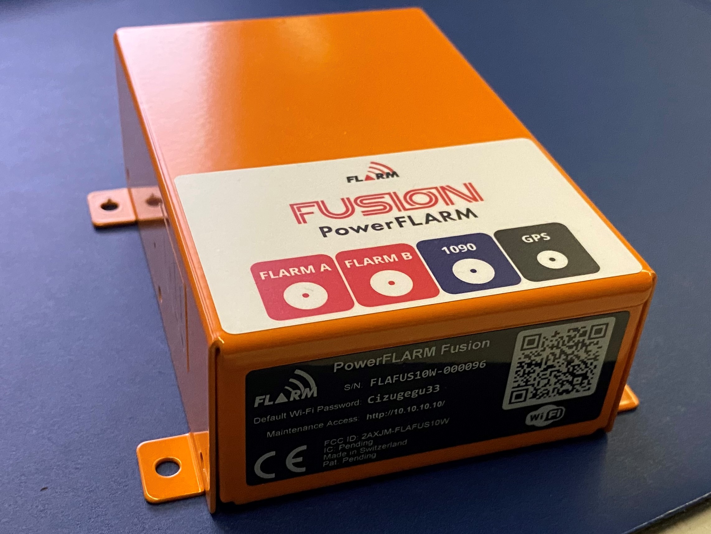
Text extracted from the exhibit documents filed with the FCC. Open a document above to read the original.
POWERFLARM FUSION INSTALLATION MANUAL Date: 2020-11-27 Version: 1.1 Page: 1 of 40 FLARM Technology Ltd Hinterbergstrasse 15 CH-6330 Cham Document Number: FTD-077 Document Status Published status Confidentiality status ☒ Draft ☐ Released ☐ Canceled ☐ Internal ☐ NDA ☒ Public Version Control Ver. Date Summary of changes 1.0 2020-11-10 Initial version 1.1 2020-11-27 Added note for RJ45 pin numbering. Conformity Declarations. 1.2 FCC and IC conformity declarations. POWERFLARM FUSION INSTALLATION MANUAL Date: 2020-11-27 Version: 1.1 Page: 2 of 40 FLARM Technology Ltd Hinterbergstrasse 15 CH-6330 Cham Document Number: FTD-077 Table of contents 1 General Overview .............................................................................. 4 1.1 System Description .................................................................. 6 1.2 Definitions .............................................................................. 7 1.2.1 Abbreviations ............................................................ 7 1.2.2 Terminology.............................................................. 8 1.3 Displays ................................................................................. 8 1.4 Radio Communication and Antennas ........................................... 8 1.5 Additional Documents, Data, and Information ............................. 10 1.6 Document Revisions ................................................................ 10 2 Installation ...................................................................................... 11 2.1 General Requirements and Advice on Installation ......................... 11 2.1.1 Minor Change and Standard Change ............................ 12 2.2 Housing ................................................................................ 12 2.3 Displays ................................................................................ 13 2.4 Connections and Cabling .......................................................... 14 2.4.1 Overview ................................................................. 14 2.4.2 General Advice ......................................................... 15 2.4.3 Circuit Breaker ......................................................... 15 2.4.4 Power Supply ........................................................... 15 2.4.5 Display ................................................................... 16 2.4.6 RJ45 – Power and Data Connections ............................ 16 2.4.7 D-sub DE-9 – Power, Data, and Audio Connections ........ 17 2.4.8 Audio Out ................................................................ 18 2.4.9 FLARM and 1090 MHz Antenna Connectors ................... 19 2.4.10 GPS Antenna (SMC Connector) ................................... 20 2.5 Antennas ............................................................................... 20 2.5.1 External Antennas .................................................... 20 2.5.2 Internal Antennas ..................................................... 22 2.6 USB Connector ....................................................................... 23 2.7 Firmware Updates ................................................................... 24 2.8 Configuration ......................................................................... 24 2.9 Annual Maintenance ................................................................ 25 POWERFLARM FUSION INSTALLATION MANUAL Date: 2020-11-27 Version: 1.1 Page: 3 of 40 FLARM Technology Ltd Hinterbergstrasse 15 CH-6330 Cham Document Number: FTD-077 2.10 Installation Verification ............................................................ 25 3 Technical Specification .................................................................... 26 4 Additional Information .................................................................... 27 4.1 Troubleshooting and Error Codes ............................................... 27 4.2 Warranty Information and Terms of Use ..................................... 27 4.3 Replacing PowerFLARM Core with PowerFLARM Fusion .................. 27 4.4 Replacing Classic FLARM with PowerFLARM Fusion ....................... 27 4.5 Conformity Declarations .......................................................... 28 4.5.1 CE .......................................................................... 28 4.5.2 FCC ........................................................................ 28 4.5.3 Industry Canada Notice and Marking ............................ 29 4.6 Maximum Antenna Gain ........................................................... 31 Appendix A – Mechanical Drawings ....................................................... 32 Appendix B – Acceptable Antennas and Cables ..................................... 33 Appendix C – FLARM Compatible Displays ............................................. 34 Appendix D – Installation Verification Checklist .................................... 36 Appendix E – End User License Agreement (EULA) ................................ 39 POWERFLARM FUSION INSTALLATION MANUAL Date: 2020-11-27 Version: 1.1 Page: 4 of 40 FLARM Technology Ltd Hinterbergstrasse 15 CH-6330 Cham Document Number: FTD-077 1 General Overview FLARM is the collision avoidance system and traffic awareness/electronic conspicuity technology used by General Aviation, light aircraft, and UAVs. It has been designed to support self-separation for both VFR and IFR in applicable airspace classes. Aircraft with a FLARM system alert the pilots when on a collision course with another aircraft. Similar to TCAS/TAS, visual and aural warnings indicate that a collision is imminent, requiring the pilots to take action. However, unlike TCAS, FLARM does not issue Resolution Advisories (RA), so pilots need to select the appropriate course of action themselves. FLARM works by calculating and broadcasting its own predicted future 3D flight path to nearby aircraft. At the same time, it receives the future flight path from surrounding ai…
Text truncated - open the document above for the full version.
SIQ Ljubljana, Mašera-Spasićeva ulica 10, SI-1000 Ljubljana, Slovenia T +386 1 4778 100, F +386 1 4778 444, [email protected], www.siq.si External photos Project file: C20201558 Date: 2021-02-01 Pages: 4 Product: Radio Module Type reference: PowerFLARM Fusion Page: 2 (4) Figure 1 Figure 2 Page: 3 (4) Figure 3 Figure 4 Page: 4 (4) Figure 5 Figure 6
SIQ Ljubljana, Mašera-Spasićeva ulica 10, SI-1000 Ljubljana, Slovenia T +386 1 4778 100, F +386 1 4778 444, [email protected], www.siq.si Internal photos Project file: C20201558 Date: 2020-12-07 Pages: 4 Product: Radio Module Type reference: PowerFLARM Fusion Page: 2 (4) Figure 1 Figure 2 Page: 3 (4) Figure 3 Figure 4 Page: 4 (4) Figure 5 Figure 6
SIQ Ljubljana, Mašera-Spasićeva ulica 10, SI-1000 Ljubljana, Slovenia T +386 1 4778 100, F +386 1 4778 444, [email protected], www.siq.si TN405E - 02 Test report Number: T251-0695/20 Project file: C20201558 Date: 2021-01-11 Pages: 102 Product: Radio Module Type reference: PowerFLARM Fusion Ratings: 12-32 Vdc Operating frequencies: 902,6 MHz - 927,4 MHz Protection class: III Trademark: Applicant: FLARM Technology Ltd. Hinterbergstrasse 15 CH-6330 Cham Switzerland Manufacturer: Placetec AG Industriestrasse 17, CH-4410 Liestal, Switzerland Place of manufacture: Placetec AG Industriestrasse 17, CH-4410 Liestal, Switzerland Summary of testing Testing method: 47 CFR Part 15, Subpart C (Clause 15.247) in conjuction with ANSI C63.10:2013 Testing location: SIQ Ljubljana, Mašera-Spasićeva ulica 10, SI-1000 Ljubljana, Slovenia Remarks: Date of receipt of test items: 2020-06-03 Number of items tested: 1 Date of performance of tests: 2020-07-03 - 2020-08-27 The test results presented in this report relate only to the items tested. The product complies with the requirements of the testing methods. / Tested by: Luka Cvajnar Approved by: Marjan Mak The report shall not be reproduced except in full. T251-0695/20 Page: 2 (102) CONTENTS page 1 GENERAL 3 1.1 EQUIPMENT UNDER TEST 3 1.2 GENERAL PRODUCT INFORMATION 3 2 0BTEST SUMMARY 4 2.1 OPERATING VOLTAGES/FREQUENCIES USED FOR TESTING 4 3 1BEMISSION TESTS (INTENTIONAL RADIATORS) 5 3.1 §15.203 ANTENNA REQUIREMENTS 5 3.2 §15.207 CONDUCTED EMISSION 6 3.3 §15.247 (A) (1) 20 DB BANDWIDTH 7 3.4 §15.247 (A) (1) TIME OF OCCUPANCY (DWELL TIME) 14 3.5 §15.247 (A) (1) NUMBER OF HOPPING FREQUENCIES 21 3.6 §15.247 (A) (1) CARRIER FREQUENCY SEPARATION 24 3.7 §15.247 (A) (1) PSEUDORANDOM FREQUENCY HOPPING SEQUENCE AND EQUAL HOOPING FREQUENCY USE 31 3.8 §15.247 (B) PEAK POWER OUTPUT 32 3.9 §15.247 (C) SPURIOUS RF CONDUCTED EMISSIONS 39 3.10 §15.247 RADIATED SPURIOUS EMISSIONS 52 3.11 §15.247 (D) BAND-EDGE COMPLIANCE OF RF CONDUCTED EMISSIONS 73 3.12 §15.247 (I) RF EXPOSURE COMPLIANCE REQUIREMENTS 82 4 TEST EQUIPMENT 83 5 CABLE LOSS AND ATTENUATION OF RADIATED EMISSION 84 6 CONVERSION FACTORS AND ALL OTHER FORMULAS 102 T251-0695/20 Page: 3 (102) 1 GENERAL History sheet Date Report No. Change Revision 2021-01-11 T251-0695/20 Initial Test Report issued. -- Environmental conditions: Ambient temperature: 15C to 35C Relative humidity: 30% to 60% Atmospheric pressure: 860 mbar to 1060 mbar 1.1 Equipment under test Radio Module Type: PowerFLARM Fusion FCC ID: 2AXJM-FLAFUS10W Tested SIQ sample number: S20204346 Auxiliary equipment used during the testing: Laptop, LENOVO, L560 1.2 General product information Supply voltage: 12-32 Vdc Rated RF output power: 16 dBm Modulation type: GFSK Operating frequency: 902.6 MHz – 927.4 MHz Number of channels: 64 Number of transmitters 2 Antenna type: Dipole antenna 915 MHz, Gain: 2.15 dBi The PowerFLARM Fusion is based on the PowerFLARM OEM suite of modules. The modules integrate the Nordic Semiconductor Single-chip 433/868/915 MHz Transceiver nRF905 using software to implement a frequency hopping spread spectrum (FHSS) radio interface with 63 channels (400 kHz spacing) from 902.6 MHz to 927.4 MHz. The system is designed to allow light aircraft and drones to communicate their locations to each other by continuously streaming their GPS locations. The system is intended to be used in aircraft only. PowerFLARM Fusion contains three (active) radio modules: The Application Module (AM) being the master (main) module, the Diversity Module (DM) being a slave (auxiliary) module, where both contain one nRF905 transceiver chip. The third module (Espressif ESP32) provides the 2.4 GHz interfaces (Bluetooth and Wi-FI). Other radio modules contained in PowerFLARM Fusion are passive, i.e., receive-only. The AM incorporates all of the functionality and software in a standalone form. The DM can only be connected to the AM, to complement the RF functionality, i.e., providing radio diversity. The DM does not contain software. T251-0695/20 Page: 4 (102) 2 0BTEST SUMMARY STANDARD Tested Sample yes no pass not pass FCC 47 CFR Part 15, Subpart C, §15.247 Note: All tests were conducted using ANSI C63.10-2013 Test Section within the report Conclusion §15.203 Antenna requirements 3.1 PASS §15.207 Conducted emission 3.2 N/A §15.247 (a) (1) 20 dB Bandwidth 3.3 PASS 99 % Bandwidth 3.3 PASS §15.247 (a) (1) Time of Occupancy (Dwell Time) 3.4 PASS §15.247 (a) (1) Number of Hopping Frequencies 3.5 PASS §15.247 (a) (1) Carrier Frequency Separation 3.6 PASS §15.247 (a) (1) Pseudorandom Frequency Hopping Sequence and Equal Hooping Frequency Use 3.7 PASS §15.247 (b) Peak Power Output 3.8 PASS §15.247 (d) Spurious RF Conducted Emissions 3.9 PASS §15.247 Radiated Spurious Emissions 3.10 PASS §15.247 (d) Band-edge Compliance of RF Conducted Emissions 3.11 PASS §15.247 (i) RF Exposure Compliance Requirements 3.12 PASS 2.1 Operating voltages/frequencies used for testing Test Operating conditions §15.207 Conducted emission / §15.247 (a) (1) 20 dB Bandwidth 12 Vdc 99 % Bandwidth 12 Vdc §15.247 (a) (1) Time of Occupancy (Dwell Time) 12 Vdc §15.247 (a) (1) Number of Hopping Frequencies 12 Vdc §15.247 (a) (1) Carrier Frequency Separation 12 Vdc §15.247 (b) Peak Power Output 12 Vdc §15.247 (d) Spurious RF Conducted Emissions 12 Vdc §15.247 Radiated Spurious Emissions 12 Vdc §15.247 (d) Band-edge Compliance of RF Conducted Emissions 12 Vdc T251-0695/20 Page: 5 (102) 3 1BEMISSION TESTS (Intentional Radiators) 3.1 §15.203 Antenna requirements Requirement An intentional radiator shall be designed to ensure that no antenna other than that furnished by the responsible party shall be used with the device. The use of a permanently attached antenna or of an antenna that uses a unique coupling to the intentional radiator shall be considered sufficient to comply with the provisions of this section. The manufacturer may design the unit so that a broken antenna can be replaced by the user, but the use o…
Text truncated - open the document above for the full version.
SIQ Ljubljana, Mašera-Spasićeva ulica 10, SI-1000 Ljubljana, Slovenia T +386 1 4778 100, F +386 1 4778 444, [email protected], www.siq.si Test setup photos Project file: C20201558 Date: 2020-10-13 Pages: 3 Product: Radio Module Type reference: PowerFLARM Fusion Page: 2 (3) Figure 1: Spurious emission 9 kHz 30 MHz Figure 2: Spurious emission 30 MHz-1000 MHz Page: 3 (3) Figure 3: Spurious emission 1-10 GHz Figure 4: Conducted measurements test setup
Hinterbergstrasse 15 · Cham, Zug · Switzerland
| # | Rule Parts | Frequency Range | Power Output |
|---|---|---|---|
| 1 | 15C | 902.6 MHz - 927.4 MHz | 52.00 mW |

Atom UAV MMCX
Equipment Class
DSS - Part 15 Spread Spectrum Transmitter
