2AXL8-ATX2410V4P1Non-Contact Vital Signs Monitor
Advanced TeleSensors, Inc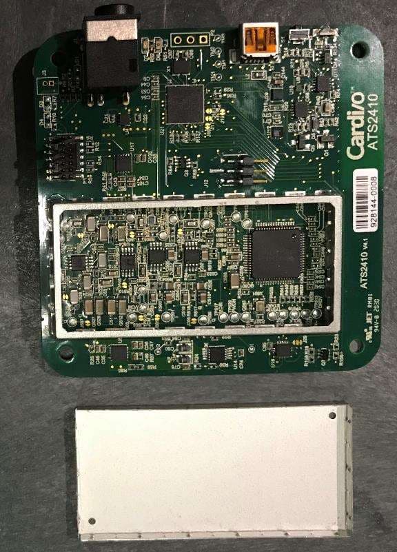
Click to zoom
Application Details
- Equipment Class
- DXX - Part 15 Low Power Communication Device Transmitter
- Date of Grant
- Oct 04, 2020
- Application Purpose
- Original Equipment
- Date of Application
- Oct 04, 2020
- Equipment Note
- Non-Contact Vital Signs Monitor
- Frequency Range
- 24133.00000000 - 24133.00000000
- Company
- Advanced TeleSensors, Inc
- Country
- United States
Documents & Files
Document Text
Text extracted from the exhibit documents filed with the FCC. Open a document above to read the original.
Users Manual
IFU-10-EUA Rev. 01 Date: 01Sep2020 Page 1 of 17 INSTRUCTIONS FOR USE CARDI/O ® [kar-dee-o] (remote patient monitor) for touchless, no-wearable use IFU-EUA Rev. 01 Date: 01Sep2020 Page 2 of 17 Device Description The Cardi/o ® Sensor device is a component of the Cardi/o ® remote patient monitoring (RPM) platform. The Cardi/o Sensor device is a wireless, no-touch/no-wearable vital signs sensor, set on a desktop or mounted to a wall to record heart rate, respiratory rate, and stress related to heart rate variability, and motion. The Cardi/o ® Sensor continuously gathers physiological data from the person being monitored and then transmits encrypted data via WiFi to the Cardi/o ® Cloud platform. The encrypted wireless data provided by the Cardi/o ® Sensor may be accessed and viewed via Cardi/o ® App for mobile phones or Cardi/o ® Central Dashboard web app for desktop computers. The data from the Cardi/o Sensor may be downloaded from the Cardi/o ® Cloud for storage or integrated into a Third-Party Relay Application via the APIs of the Cardi/o ® Software Library. The data provided by the Cardi/o Sensor is intended to aid caregivers in making diagnoses by providing additional information. During normal operation, data is collected via touchless radar sensing capability of the Cardi/o ® Sensor and transmitted immediately to the Cardi/o ® Cloud via WiFi. A continuous connection is needed between the Cardi/o ® Sensor and the Internet to facilitate continuous physiological data transmission. The continuous wireless transmission of data occurs with an update rate of 2 seconds between data collection and transmission. Patients may opt in to request assistance from healthcare providers through predefined alarm thresholds that, when exceeded, send alerts via a wall-mounted transceiver that is connected to the cloud. Indications for Use The Cardi/o ® RPM is a wireless “no-wearable” remote monitoring system intended for use by healthcare professionals for continuous collection of physiological data in healthcare settings as well as in environments where healthcare is administered, such as home healthcare services, assisted living and skilled nursing facilities. This physiological data can include heart rate, respiratory rate, heart rate variability, and motion. The RPM may be used for synchronous or asynchronous for telemedicine consultations. The Cardi/o ® Sensor is intended for use on general care patients who are 18 years of age or older who may be susceptible to decubitus ulcers of the skins, such as the elderly, for use as a general patient monitor, to provide physiological information. The collection and transmission of data is performed on the device. The data from the device is intended for use by healthcare professionals as an aid to remote diagnosis and treatment while preventing the spread of communicable diseases such as COVID-19. The device can be used on patients unable or averse to wearable patient monitors, such as patients living with dementia or autism. The device is not intended for use on critical care patients. The data provided by the Cardi/o ® Sensor may also be intended for trained technicians at a remote site to review the data and determine if they concur with the analysis made by the algorithm in the Cardi/o ® Sensor. The data collected by the Cardi/o ® Sensor is an adjunct to clinical assessment; clinician review of the data should precede any diagnosis or therapeutic intervention. IFU-EUA Rev. 01 Date: 01Sep2020 Page 3 of 17 Contraindications • The Cardi/o ® Sensor is not intended as a stand-alone diagnostic monitor for vital signs, but the data may be applicable for use in diagnosis. Warnings • Depending on wireless connectivity, a temporary interruption of data transmission is possible, which may impact continuous or real-time monitoring. Limited data will be stored on the device for transfer once connectivity is reestablished. • The Cardi/o ® Sensor is designed to monitor one individual at a time. Having more than one individual in the field of view of the sensor may produce skewed data that may not represent the parameters of the intended subject. • Disturbances to cardiac-respiratory signals include distortions due to foreign interference and noise artifacts may occur when using the Cardi/o ® Sensor. Do not rely entirely upon heart rate signals of the Cardi/o ® Sensor. Keep patients under close surveillance. • Automated interpretation of heart rate variability by the Cardi/o ® Sensor is a valuable tool when used properly. However, no automated interpretation is completely reliable, and a qualified physician shall review the interpretations before treatment, or non-treatment, of any patient. • Heart rate, respiratory rate, stress level (HRV), and motion data will not be transmitted or stored if the Sensor is not powered. • The patient must be in the field of view of the Cardi/o ® Sensor to collect physiological data. • Clinical validation has not been performed on patients who are pregnant or breastfeeding. Precautions • For data to be sent to a healthcare professional for review: o The Cardi/o ® Sensor must be properly used by the patient. o The patient must remain in range of their Sensor device. o The Cardi/o ® Sensor must have adequate power for data transmission. Notification of interruption in data collection of the Cardi/o ® Sensor will be indicated on the Cardi/o ® App when the Sensor device is offline and may also be sent via SMS Text if this feature is enabled. o The Sensor device must remain connected to the Internet and functional for data transmission. Wireless connectivity must be active for transmission of data from the Sensor device to the Cardi/o ® . • The healthcare professional can be notified when there are interruptions in data connectivity if this feature is enabled. • Physiological data collected by the Cardi/o ® Sensor for patients experiencing stress may indicate slightly higher or lower respiratory rate values, compared to visual observation. • Th…
Text truncated - open the document above for the full version.
Cover Letter(s)
3815 Jarrett Way, A100, Austin, TX 78782 USA T (512) 852-8057 Toll-free (888) 292-2208 advancedtelesensors.com Date: 21/9/2020 TUV SUD America Inc. 10 Centennial Drive Peabody, MA 01960, USA FCC ID: IC ID: Dear Sir or Madam, We, Advanced TeleSensors, Inc, 3815 Jarrett Way, Ste A 100, Austin, TX 78728, hereby authorize Eric Lifsey of Professional Testing (EMI) Inc. to act as our agent in all matters relating to applications for equipment authorization, including the signing of all documents relating to these matters. Yours sincerely, Name: Robert W. Hohman Title: Engineering Mgr 2AXL8-ATX2410V4P1 n/a
Cover Letter(s)
3815 Jarrett Way, A100, Austin, TX 78782 USA T (512) 852-8057 Toll-free (888) 292-2208 advancedtelesensors.com Date: 29/9/2020 Federal Communications Commission Equipment Authorization Branch 7435 Oakland Mills Road Columbia, MD 21046 Confidentiality Request FCC ID: 2AXL8-ATX2410V4P1 Pursuant to Sections 0.457(d)(1)(ii) and 0.459 of the Commission’s Rules, Advanced TeleSensors, Inc hereby requests permanent confidential treatment of information accompanying this application as outlined below: Schematics-ATS2410-V4.1_Schematic 1.6.pdf Bill of Materials/Parts List-BOM_ATS2410.pdf Block Diagram-BlockDiag_Cardio_ATS2410.pdf Theory of Operation/TOO_ATX2410_092820.pdf Advanced TeleSensors, Inc also hereby requests short-term confidential treatment of information accompanying this application as outlined below for a period of period of 90 days: Internal Photos External Photos User Manual Test Set-up Photographs The above materials contain trade secrets and proprietary information not customarily released to the public. The public disclosure of these matters might be harmful to the Applicant and provide unjustified benefits to its competitors. The Applicant understands that pursuant to Rule 0.457(d)(1)(ii), disclosure of this Application and all accompanying materials will not be made before the date of the Grant for this Application. Yours sincerely, Name: Robert W. Hohman Company: Advanced TeleSensors, Inc
External Photos
21941 External Photos Page 1 of 3 Side 1 of 6 Side 2 Side 3 Side 4 Side 5 Side 6 of 6 ***
ID Label/Location Info
FCC Label for ATS2410 The Square on the left side (as you view the label) will contain a QR Code with MAC ID and Serial number of this device. The rectangular area in the bottom-center will contain a barcode of the Serial Number of this device. The label would be placed on the back of the enclosure as indicated. The size of the label is 2-3/8” x 1-1/4”.
Internal Photos
21941 Internal Photos Page 1 of 3 Antenna/Top Side Back Side with Shield Back Side Shield Removed ***
RF Exposure Info
21941 ATS: ATX2410 Exposure Supplemental Report (Rev01) Page 1 of 3 Professional Testing (EMI) Inc. 1601 North A.W. Grimes Blvd., Suite B Round Rock, TX 78665 e-mail: [email protected] (512) 244-3371 Fax: (512) 244-1846 1.0 Maximum Permissible Exposure Evaluation (Supplements the test report.) The measured power is considered for the intended use of the device and resulting RF exposure to the user. 1.2 Criteria Section Reference Date 447498 D01 General RF Exposure Guidance v06 // RSS-102 Issue 5 2 Oct 2020 1.3 Procedure Using measurement of peak power and considering the intended application, determine the permissible exposure level, applicability of exclusion, or whether additional exposure tests (SAR) are indicated. When applicable justify conclusion for selected exposure level and separation distance. 1.4 Power to Exposure Calculation This device is operated typically indoors, either wall-mounted or on a desk. The operating band is 24000-24250 MHz. Power is determined from the measured field strength. The uncontrolled public separation distance is 20 cm. Table 1.4.1 Power Calculation Measured Power Field Strength dBμV/m* At Distance EIRP Power dBm Source Duty Cycle Factor dB Calculated Average Power dBm Calculated EIRP mW 107.7 3 m 12.5 0 12.5 17.7 *This is the peak measurement. 1.5 SAR Exemption Calculation – FCC 21941 ATS: ATX2410 Exposure Supplemental Report (Rev01) Page 2 of 3 Professional Testing (EMI) Inc. Field density is determined at 20 cm as: S = EIRP / (4 π 20 2 ) Ref. FCC Bulletin OET-65 Equation (4) S = 17.7 mW / 5026.55 cm 2 S = 0.0035 mW/cm 2 Therefore 0.0035 mW/cm 2 < 1 mW/cm 2 This device meets the OET 65 Limits for General Population/Uncontrolled Exposure, limit for field density of 1 mW/m 2 criteria in table (B), row 1500-100000 MHz. 1.6 SAR Exemption Calculation – IC Table 4 line 15000-150000 MHz power density limit: 10 W/m 2 or 1 mW/cm 2 Therefore 0.0035 mW/cm 2 < 1 mW/cm 2 This device meets the Table 4 Field Strength Limits for Devices Used by the General Public (Uncontrolled Environment), row 15000-150000 MHz, limit for field density of 10 W/m 2 criteria (or restated as 1 mW/cm 2 ) in RSS-102. Signed: Eric Lifsey 21941 ATS: ATX2410 Exposure Supplemental Report (Rev01) Page 3 of 3 Professional Testing (EMI) Inc. ***
Test Report
Project 21941-15 Advanced TeleSensors, Inc ATX2410 Wireless Certification Report Prepared for: Advanced TeleSensors, Inc. 3815 Jarrett Way Suite A100 Austin, TX 78728-1227 By Professional Testing (EMI), Inc. 1601 North A.W. Grimes Blvd., Suite B Round Rock, Texas 78665 1 Oct 2020 Reviewed by Written by Larry Finn Chief Technical Officer Eric Lifsey EMC Engineer Advanced TeleSensors, Inc – ATX2410 21941 Professional Testing (EMI) Inc. Page 2 of 26 Revision History Revision Number Description Date Draft 2 Draft for review. Added mains conducted emissions. 2 Oct 2020 Final 1 5 Oct 2020 Errata: None Advanced TeleSensors, Inc – ATX2410 21941 Professional Testing (EMI) Inc. Page 3 of 26 Table of Contents Revision History ............................................................................................................................................................. 2 1.0 Introduction .......................................................................................................................................................... 5 1.1 Scope ............................................................................................................................................................... 5 1.2 EUT Description ............................................................................................................................................. 5 1.3 EUT Operation ................................................................................................................................................ 5 1.4 Modifications to Equipment ............................................................................................................................ 5 1.5 Test Site .......................................................................................................................................................... 5 1.6 Measurement Correction Methods .................................................................................................................. 5 1.7 Applicable Documents .................................................................................................................................... 6 2.0 Fundamental Power, Clause 15.249(a), RSS-210 B.10 Table B2 ........................................................................ 7 2.1 Test Procedure ................................................................................................................................................ 7 2.2 Test Criteria .................................................................................................................................................... 7 2.3 Test Results ..................................................................................................................................................... 7 3.0 Occupied Bandwidth, Clause 2.1049, RSS-Gen 6.7 ............................................................................................ 9 3.1 Test Procedure ................................................................................................................................................ 9 3.2 Test Criteria .................................................................................................................................................... 9 3.3 Test Results ..................................................................................................................................................... 9 4.0 Radiated Spurious Emissions, Transmit Mode, Clause 15.249(a), RSS-210 Table B.2 .................................... 10 4.1 Test Procedure .............................................................................................................................................. 10 4.2 Test Criteria .................................................................................................................................................. 10 4.3 Test Results ................................................................................................................................................... 10 4.3.1 Up to 1 GHz ........................................................................................................................................ 11 4.3.2 Up to 18 GHz ...................................................................................................................................... 12 4.3.3 Up to 26.5 GHz.................................................................................................................................... 13 4.3.4 Up to 40 GHz ...................................................................................................................................... 14 4.3.1 Up to 50 GHz ...................................................................................................................................... 15 4.3.2 Up to 75 GHz ...................................................................................................................................... 16 4.3.3 Up to 100 GHz .................................................................................................................................... 17 5.0 Antenna Construction Requirements, Clause 15.203, RSS-Gen 6.8 .................................................................. 18 5.1 Procedure ...................................................................................................................................................... 18 5.2 Criteria .......................................................................................................................................................... 18 5.3 Results ........................................................................................................................................................... 18 6.0 Equipment ............................................................................................................................…
Text truncated - open the document above for the full version.
Test Setup Photos
21941 Test Setup Photos Page 1 of 5 Radiated Emissions to 1 GHz Radiated to 1 GHz Radiated Emissions 1 to 18 GHz Radiated Emissions 1 to 18 GHz Radiated Emissions 1 to 18 GHz Radiated 18 to 26.5 GHz Radiated 18 to 26.5 GHz Radiated 26.5 to 100 GHz Mains Conducted Mains Conducted ***
Contact Information
Applicant
Robert W Hohman(Engr Mgr)
Test Firm
Professional Testing (EMI), Inc.Larry Finn
Technical Specifications
| # | Rule Parts | Frequency Range | Power Output |
|---|---|---|---|
| 1 | 15C | 24.13 GHz - 24.13 GHz | - |