FCCID.CO- FCC ID Database
HomeCompaniesEquipment ClassesSearch

© 2026 FCC ID Database. All rights reserved.

AboutContactData sourced from FCC public records
  1. Home/
  2. Guangdong Uooser Acoustic Technology Co., LTD/
  3. 2AXLX-M12

2AXLX-M12Bluetooth Earphone M12

Guangdong Uooser Acoustic Technology Co., LTD
Bluetooth Earphone M12 - FCC ID 2AXLX-M12 - Guangdong Uooser Acoustic Technology Co., LTD
Click to zoom

Application Details

Equipment Class
DSS - Part 15 Spread Spectrum Transmitter
Date of Grant
Sep 22, 2020
Application Purpose
Original Equipment
Date of Application
Sep 22, 2020
Equipment Note
Bluetooth Earphone M12
Frequency Range
2402.00000000 - 2480.00000000
Company
Guangdong Uooser Acoustic Technology Co., LTD
Country
China

Documents & Files

Select a file to view

Users Manual

↗

Cover Letter(s)

↗
↗
↗

External Photos

↗

ID Label/Location Info

↗

Internal Photos

↗

RF Exposure Info

↗

Test Report

↗
↗

Test Setup Photos

↗

Document Text

Text extracted from the exhibit documents filed with the FCC. Open a document above to read the original.

Users Manual

M12 User Manual Wearing method Gently slide into ears, the earbuds tail align with the mouth Adjust the earbuds to where it doesn‘t move while wobbling head Main user interface A.Charging point B.Function button C.Microphone D.Charging USB Port E.Status LED Start Here a. Open Charging Dock case,two earbuds will power on and pair with each other automatically Open Close b. Pairing with cellphone Bluetooth Turn on Bluetooth Device name Available Devices M12 Available Devices M12 Open cellphone bluetooth and set it as Open detection, when “M12” appears in available devices, press to connect. The LED will be off after connected. (V oice Notice: Connected) c. Power off Put back the earbud to the charging dock and close the cap,the earbuds will power off,and the dock will charge the earbuds automatically. (Voice Notice: Power off) Open the case,earbud LED flash in white,two earbuds will power on and pair with each other automatically (Voice Notice:Power on ---> TWS connected --->Pairing) Charging More functions a.The LED flashes in Red and there is a Voice Notice when the Battery Power Low. d.It takes about 1.5h to fully charge the earbuds and charging dock batteries b.Without external power supply, the LED is on in red while charging and will be off after fully charged. c.With external power supply, the LED flash in blue while charging and will be on in blue after fully charged a.Touch the function button once to answer calls,press Funtion Button twice to reject calls. b.When playing music,To pause,please press the function button once;To play the previous song, please press and hold 2s for left earbud function button.To play next song,please press and hold 2s for right earbud function button; c.To increase volume,please press the function button of left earbud twice; To decrease volume,please press function button of the right earbud twice; To activate siri,please press function button three times. Status LED Charging USB Function Button Important Notice for Single Earbud using Manual pairing Press twice LR a.The earbuds can be used individually (each earbud pairs to separate cellphone) b.Open charging Dock cap,take out either earbud,wait for 10s, the LED flashes in white,and then open cellphone bluetooth and set it as open detection,when “M12”appears in available devices, press to connect. The LED will be off. (Voice Notice: Power on ---> Pairing) c.It will automatically connect to the cellphone,if it connected previously. Basic Parameter Important Notice Product NameM12Operation range10m Charging time1.5 hoursCall time5 hours Music Time4 hours Charging Input5V 300mA Battery TypePolymer Li-Ion Battery Earbud weight4g+4g Please make sure the product is fully charged before initial use. Please use the brand adaptor complying safety requirements to charge this product. If your cellphone can not find “M12”, please double check if your cellphone Bluetooth is at “Equipment visible mode”. After initial pairing,the earbuds will be automatically paired for repeat use. If no use for a long time, need to follow up pairing procedures to pair with the cellphone. If there is only one earbud has sound while in music mode, please restart the earbuds or re-pair manually. Security warning Please use the product in the temperature between 0 C-45 C. When the enviroment temperature is too high or low, it may cause the product malfunction. Please keep the product dry, do not contact water or humidity enviroment Please do not drop, throw, pull/drag the product to prevent damage. Please power off before clean the product. Please use the product at proper volume while listenning music or answering call, long time at high volume usage could lead to permanent hearing loss. The built in battery is not dismountable, please do not replace by yourself. If it's really necessary, please ask help from authorized service center. Please dispose the product according to local law, can not treat it as domestic garbage. Without adult supervision, please keep the product out of reach of children, the swallow of small components included may cause asphyxia. Warranty This product is covered under warranty for a period of one year from the date of purchase limited to normal use and maintenance of the machine parts, materials and functions. Problems and failures verified upon fur- ther identification, will be provided free repair and replacement parts. Excluding the following: A. Headset is beyond the warranty period; B. User does not follow the instructions. so that the headphone wire and earplug broken. C. Without the authorization to dismount, repair, alt eration structures; D. Can’t provide proof of purchase. E. Man made damage. F. Due to natural disasters and other force majeure (such as earthquakes, fires) product failure of damage causes; Warranty Card QC Report info Model # Inspector Date User’s name User’s telephone# User’s Add Date of purchase Invoice # Dealer’s name Dealer’s Add Dealer’s telephone# P/N:16-4BA10101D 1stly make sure the earbuds don’t connect any bluetooth devices. 2ndlyput two earbuds close within 10cm and press & hold two function buttons for 2s to power on both earbuds. 3rdlypress either function button twice,auto pairing completed when one LED flashes in white the other one is off. 4thlypress & hold either function button for 5s,two earbuds turn off at the same time,manual pairing completed. Questions & Answers AnswersReasonsQuestions earbuds not “power on” earbuds pairing failure charging dock LED not light on while putting in earbuds low volume charging dock not charging can’t find earbuds pairing name or pairing failure with cellphone charing protection earbuds not in pairing mode Re-“power on”the earbuds power off & re-power on cellphone celllphone bluetooth App error charge the charging Dock by external power the volume setting of the earbuds & cellphone not synchronized turn on cellphone bluetooth & synchronized its volume setting with the connected earbuds can’t detect the earbuds while they are fu…

Text truncated - open the document above for the full version.

Cover Letter(s)

(Guangdong Uooser Acoustic Technology Co., LTD) Federal Communications Commission Authorization and Evaluation Division Confidentiality Request regarding application for certification of FCC ID: 2AXLX-M12 Pursuant to Sections 0.457 and 0.459 of the Commission’s Rules, we hereby request confidential treatment of information accompanying this application as outlined below: Exhibit Type File Name Block Diagram, Schematics, Operational Description Block Diagram Schematics Operational Description The above materials contain trade secrets and proprietary information not customarily released to the public. The public disclosure of these materials may be harmful to the applicant and provide unjustified benefits to its competitors. The applicant understands that pursuant to Section 0.457 of the Rules, disclosure of this application and all accompanying documentation will not be made before the date of the Grant for this application. Sincerely, ( Wei Ming) Rev 11/20/07

Cover Letter(s)

Guangdong Uooser Acoustic Technology Co., LTD Model Difference 2020-09-17 EUT NAME: Bluetooth Earphone M12 FCC ID: 2AXLX-M12 MODEL : M12, MA12, MA12-H All the model are the same circuit and RF module, only for model name and color. Regards Sincerely Client’s signature Client’s name / title : Wei Ming / Manager Contact information / address: Room 301-2, building 9, longbi industrial zone, no.27, dafa road, dafa pu community, bantian street, longgang district, China

Cover Letter(s)

(Guangdong Uooser Acoustic Technology Co., LTD) Federal Communications Commission Authorization and Evaluation Division 1435 Oakland Mills Road Columbia, MD 21046 Date: 2020/09/04 SUBJECT: FCC Application for FCC ID: 2AXLX-M12 To Whom It May Concern: We, the undersigned, hereby authorize Alan Mei at Shenzhen BCTC Testing Co., Ltd. on our behalf, to apply to the Federal Communications Commission on our equipment. Any and all acts carried out by Alan Mei of Shenzhen BCTC Testing Co., Ltd. on our behalf shall have the same effect as acts of our own. This is to advise that we are in full compliance with the Anti- Drug Abuse Act. We, the applicant, are not subject to a denial of federal benefits pursuant to Section 5301 of the Anti-Drug Act of 1988, 21 USC853a, and no party to the application is subject to a denial of federal benefits pursuant to that section. Regards, ( Wei Ming)

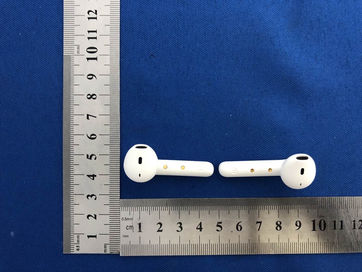
External Photos

External Photos

ID Label/Location Info

Label & label location FCC ID: 2AXLX-M12 Label location Label location

Internal Photos

Internal Photos Antenna

RF Exposure Info

RF EXPOSURE EVALUATION METHOD FCC ID: 2AXLX-M12 SAR Test Exclusion Thresholds for 100 MHz – 6 GHz and ≤ 50 mm Approximate SAR Test Exclusion Power Thresholds at Selected Frequencies and Test Separation Distances are illustrated in the following Table. The 1-g and 10-g SAR test exclusion thresholds for 100 MHz to 6 GHz at test separation distances ≤ 50 mm are determined by: [(max. power of channel, including tune-up tolerance, mW)/(min. test separation distance, mm)] · [√f(GHz)] ≤ 3.0 for 1-g SAR and ≤ 7.5 for 10-g extremity SAR,where f(GHz) is the RF channel transmit frequency in GHz Power and distance are rounded to the nearest mW and mm before calculation The result is rounded to one decimal place for comparison The test exclusions are applicable only when the minimum test separation distance is ≤ 50 mm and for transmission frequencies between 100 MHz and 6 GHz. When the minimum test separation distance is < 5 mm, a distance of 5 mm is applied to determine SAR test exclusion. BT-EDR max possible output power (PK,conducted):-1±1dbm 1. 5dBi logarithmic terms convert to numeric result is nearly 1.413 0dBm=1.00mW 2402MHz [(max. power of channel, including tune-up tolerance, mW)/(min. test separation distance,mm)] · [√f(GHz)]=1.00/5*√2. 402 =0. 31≤3.0 Threshold at which no SAR required is 10mw and ≤ 3.0 for 1-g SAR, Separation distance is 5mm. Modulation Frequency (MHz) Output Power (dBm) Max Antenna Gain (dBi) GFSK 2402 -2.22 1.5 GFSK 2441 -2.03 1.5 GFSK 2480 -2.39 1.5 Pi/4 DQPSK 2402 -1.34 1.5 Pi/4 DQPSK 2441 -1.13 1.5 Pi/4 DQPSK 2480 -1.48 1.5 2441MHz [(max. power of channel, including tune-up tolerance, mW)/(min. test separation distance,mm)] · [√f(GHz)]= 1.00/5*√2.441 =0.31≤3.0 Threshold at which no SAR required is 10mw and ≤ 3.0 for 1-g SAR, Separation distance is 5mm. 2480MHz [(max. power of channel, including tune-up tolerance, mW)/(min. test separation distance,mm)] · [√f(GHz)]=1.00/5*√2.48=0. 31≤3.0 Threshold at which no SAR required is 10mw and ≤ 3.0 for 1-g SAR, Separation distance is 5mm. Conclusion: No SAR is required.

Test Report

No.:BCTC/RF-EMC-007 Page: 1 of 61 Edition:A.1 TEST REPORT Shenzhen BCTC Testing Co., Ltd. Report No.: BCTC2009000004E Applicant: Guangdong Uooser Acoustic Technology Co., LTD Product Name: Bluetooth Earphone M12 Model/Type Ref.: M12 Tested Date: Aug. 31, 2020 to Sept. 07, 2020 Issued Date: Sept. 07, 2020 Report No.: BCTC2009000004E No.:BCTC/RF-EMC-007 Page: 2 of 61 Edition:A.1 FCC ID: 2AXLX-M12 Compiled by: Reviewed by: Approved by: Willem Wang Eric Yang Zero Zhou/Manager The test report is effective only with both signature and specialized stamp.This result(s) shown in this report refer only to the sample(s) tested. Without written approval of Shenzhen BCTC Testing Co., Ltd, this report can’t be reproduced except in full.The tested sample(s) and the sample information are provided by the client. Product Name: Bluetooth Earphone M12 Trademark: N/A Model/Type Ref.: M12 MA12, MA12-H Prepared For: Guangdong Uooser Acoustic Technology Co., LTD Address: Room 301-2, building 9, longbi industrial zone, no.27, dafa road, dafa pu community, bantian street, longgang district, China Manufacturer: Guangdong Uooser Acoustic Technology Co., LTD Address: Room 301-2, building 9, longbi industrial zone, no.27, dafa road, dafa pu community, bantian street, longgang district, China Prepared By: Shenzhen BCTC Testing Co., Ltd. Address: 1-2F, East of B Building, Pengzhou Industrial, Fuyuan 1st Road, Qiaotou Community, Fuyong Street, Bao’an District, Shenzhen, China Sample Received Date: Aug. 31, 2020 Sample tested Date: Aug. 31, 2020 to Sep. 07, 2020 Issue Date: Sep. 07, 2020 Report No.: BCTC2008000940-1E Test Standards FCC Part15.247 ANSI C63.10-2013 Test Results PASS Remark: This is Bluetooth Classic radio test report. Report No.: BCTC2009000004E No.:BCTC/RF-EMC-007 Page: 3 of 61 Edition:A.1 TABLE OF CONTENT Test Report Declaration Page 1. VERSION ............................................................. 5 2. TEST SUMMARY ...................................................... 6 3. MEASUREMENT UNCERTAINTY........................................ 7 4. PRODUCT INFORMATION AND TEST SETUP ............................ 8 4.1 Product Information ..................................................... 8 4.2 Test Setup Configuration ................................................ 8 4.3 Support Equipment ..................................................... 9 4.4 Channel List ........................................................... 9 4.5 Test Mode ............................................................ 10 4.6 table of parameters of text software setting ................................ 10 5. TEST FACILITY AND TEST INSTRUMENT USED ........................ 11 5.1 Test Facility ........................................................... 11 5.2 Test Instrument Used .................................................. 11 6. CONDUCTED EMISSIONS ............................................. 13 6.1 Block Diagram Of Test Setup ........................................... 13 6.2 Limit ................................................................. 13 6.3 Test procedure ........................................................ 13 6.4 EUT operating Conditions .............................................. 13 6.5 Test Result ........................................................... 14 7. RADIATED EMISSIONS ............................................... 16 7.1 Block Diagram Of Test Setup ........................................... 16 7.2 Limit ................................................................. 17 7.3 Test procedure ........................................................ 18 7.4 EUT operating Conditions .............................................. 19 7.5 Test Result ........................................................... 20 8. RADIATED BAND EMISSION MEASUREMENT AND RESTRICTED BANDS OF OPERATION .......................................................... 24 8.1 Block Diagram Of Test Setup ........................................... 24 8.2 Limit ................................................................. 24 8.3 Test procedure ........................................................ 25 8.4 EUT operating Conditions .............................................. 25 8.5 Test Result ........................................................... 26 9. CONDUCTED EMISSION .............................................. 27 9.1 Block Diagram Of Test Setup ........................................... 27 9.2 Limit ................................................................. 27 9.3 Test procedure ........................................................ 27 9.4 Test Result ........................................................... 28 10. 20 DB BANDWIDTH .................................................. 34 10.1 Block Diagram Of Test Setup .......................................... 34 10.2 Limit ................................................................ 34 10.3 Test procedure ....................................................... 34 10.4 Test Result .......................................................... 35 Report No.: BCTC2009000004E No.:BCTC/RF-EMC-007 Page: 4 of 61 Edition:A.1 11. MAXIMUM PEAK OUTPUT POWER .................................... 39 11.1 Block Diagram Of Test Setup .......................................... 39 11.2 Limit ................................................................ 39 11.3 Test procedure ....................................................... 39 11.4 Test Result .......................................................... 40 12. HOPPING CHANNEL SEPARATION .................................... 44 12.1 Block Diagram Of Test Setup .......................................... 44 12.2 Limit ................................................................ 44 12.3 Test procedure ....................................................... 44 12.4 Test Result .......................................................... 45 13. NUMBER OF HOPPING FREQUENCY .................................…

Text truncated - open the document above for the full version.

Test Report

Report No.: BCTC2009000004E No.:BCTC/RF-EMC-007 Page: 41 of 61 Edition:A.1 GFSK Middle Channel GFSK High Channel Report No.: BCTC2009000004E No.:BCTC/RF-EMC-007 Page: 42 of 61 Edition:A.1 Pi/4 DQPSK Low Channel Pi/4 DQPSK Middle Channel Report No.: BCTC2009000004E No.:BCTC/RF-EMC-007 Page: 43 of 61 Edition:A.1 Pi/4 DQPSK High Channel Report No.: BCTC2009000004E No.:BCTC/RF-EMC-007 Page: 44 of 61 Edition:A.1 12. HOPPING CHANNEL SEPARATION 12.1 Block Diagram Of Test Setup 12.2 Limit Frequency hopping systems shall have hopping channel carrier frequencies separated by a minimum of 25 kHz or the 20 dB bandwidth of the hopping channel, whichever is greater. Alternatively, frequency hopping systems operating in the 2400-2483.5 MHz band may have hopping channel carrier frequencies that are separated by 25 kHz or two-thirds of the 20 dB bandwidth of the hopping channel, whichever is greater, provided the systems operate with an output power no greater than 0.125W. 12.3 Test procedure 1. Remove the antenna from the EUT and then connect a low RF cable from the antenna port to the spectrum. 2. Set the spectrum analyzer: RBW = 30kHz. VBW = 100kHz , Span = 2.0MHz. Sweep = auto; Detector Function = Peak. Trace = Max hold. 3. Allow the trace to stabilize. Use the marker-delta function to determine the separation between the peaks of the adjacent channels. The limit is specified in one of the subparagraphs of this Section Submit this plot. Report No.: BCTC2009000004E No.:BCTC/RF-EMC-007 Page: 45 of 61 Edition:A.1 12.4 Test Result Modulation Test Channel Separation (MHz) Limit(MHz) Result GFSK Low 1.000 0.522 PASS GFSK Middle 1.002 0.521 PASS GFSK High 1.000 0.532 PASS Pi/4 DQPSK Low 0.996 0.821 PASS Pi/4 DQPSK Middle 1.000 0.822 PASS Pi/4 DQPSK High 1.002 0.811 PASS Test plots GFSK Low Channel Report No.: BCTC2009000004E No.:BCTC/RF-EMC-007 Page: 46 of 61 Edition:A.1 GFSK Middle Channel GFSK High Channel Report No.: BCTC2009000004E No.:BCTC/RF-EMC-007 Page: 47 of 61 Edition:A.1 Pi/4 DQPSK Low Channel Pi/4 DQPSK Middle Channel Report No.: BCTC2009000004E No.:BCTC/RF-EMC-007 Page: 48 of 61 Edition:A.1 Pi/4 DQPSK High Channel Report No.: BCTC2009000004E No.:BCTC/RF-EMC-007 Page: 49 of 61 Edition:A.1 13. NUMBER OF HOPPING FREQUENCY 13.1 Block Diagram Of Test Setup 13.2 Limit Frequency hopping systems in the 2400-2483.5 MHz band shall use at least 15 channels. 13.3 Test procedure 1. Remove the antenna from the EUT and then connect a low RF cable from the antenna port to the spectrum. 2. Set the spectrum analyzer: RBW = 100kHz. VBW = 300kHz. Sweep = auto; Detector Function = Peak. Trace = Max hold. 3. Allow the trace to stabilize. It may prove necessary to break the span up to sections. in order to clearly show all of the hopping frequencies. The limit is specified in one of the subparagraphs of this Section. 4. Set the spectrum analyzer: Start Frequency = 2.4GHz, Stop Frequency = 2.4835GHz. Sweep=auto; Report No.: BCTC2009000004E No.:BCTC/RF-EMC-007 Page: 50 of 61 Edition:A.1 13.4 Test Result Test Plots: 79 Channels in total GFSK Pi/4 DQPSK Report No.: BCTC2009000004E No.:BCTC/RF-EMC-007 Page: 51 of 61 Edition:A.1 14. DWELL TIME 14.1 Block Diagram Of Test Setup 14.2 Limit Frequency hopping systems in the 2400-2483.5 MHz band shall use at least 15 channels. The average time of occupancy on any channel shall not be greater than 0.4 seconds within a period of 0.4 seconds multiplied by the number of hopping channels employed. Frequency hopping systems may avoid or suppress transmissions on a particular hopping frequency provided that a minimum of 15 channels are used. 14.3 Test procedure 1. Remove the antenna from the EUT and then connect a low RF cable from the antenna port to the spectrum. 2. Set spectrum analyzer span = 0. Centred on a hopping channel; 3. Set RBW = 1MHz and VBW = 3MHz.Sweep = as necessary to capture the entire dwell time per hopping channel. Set the EUT for DH5, DH3 and DH1 packet transmitting. 4. Use the marker-delta function to determine the dwell time. If this value varies with different modes of operation (e.g.. data rate. modulation format. etc.). repeat this test for each variation. The limit is specified in one of the subparagraphs of this Section. Submit this plot(s). Report No.: BCTC2009000004E No.:BCTC/RF-EMC-007 Page: 52 of 61 Edition:A.1 14.4 Test Result DH5 Packet permit maximum 1600 / 79 / 6 hops per second in each channel (5 time slots RX, 1 time slot TX). DH3 Packet permit maximum 1600 / 79 / 4 hops per second in each channel (3 time slots RX, 1 time slot TX). DH1 Packet permit maximum 1600 / 79 /2 hops per second in each channel (1 time slot RX, 1 time slot TX). So, the Dwell Time can be calculated as follows: DH5:1600/79/6*0.4*79*(MkrDelta)/1000 DH3:1600/79/4*0.4*79*(MkrDelta)/1000 DH1:1600/79/2*0.4*79*(MkrDelta)/1000 Remark: Mkr Delta is once pulse time. Modulation Channel Data Packet pulse time(ms) Dwell Time(s) Limits(s) GFSK Middle DH1 0.429 0.137 0.4 DH3 1.698 0.272 0.4 DH5 2.960 0.316 0.4 Pi/4DQPSK Middle 2DH1 0.444 0.142 0.4 2DH3 1.710 0.274 0.4 2DH5 2.960 0.316 0.4 Test Plots GFSK DH1 Middle Channel Report No.: BCTC2009000004E No.:BCTC/RF-EMC-007 Page: 53 of 61 Edition:A.1 GFSK DH3 Middle Channel GFSK DH5 High Middle Channel Report No.: BCTC2009000004E No.:BCTC/RF-EMC-007 Page: 54 of 61 Edition:A.1 Pi/4DQPSK DH1 Middle Channel Pi/4DQPSK DH3 Middle Channel Report No.: BCTC2009000004E No.:BCTC/RF-EMC-007 Page: 55 of 61 Edition:A.1 Pi/4DQPSK DH5 Middle Channel Report No.: BCTC2009000004E No.:BCTC/RF-EMC-007 Page: 56 of 61 Edition:A.1 15. ANTENNA REQUIREMENT 15.1 Limit 15.203 requirement: For intentional device, according to 15.203: an intentional radiator shall be designed to ensure that no antenna other than that furnished by the responsible party shall be used with the device. 15.2 Test Result The EUT antenna is Chip antenna, fulfill the requirement of this section. Report No.: BCTC2009000004E No.:BCTC/RF-EMC-007 Page: 57 of 61 Edition:A.1 16. EUT PHOTOGRAPHS EUT Phot…

Text truncated - open the document above for the full version.

Test Setup Photos

Report No.: BCTC2009000004E No.:BCTC/RF-EMC-007 Page: 59 of 61 Edition:A.1 17. EUT TEST SETUP PHOTOGRAPHS Conducted emissions Radiated Measurement Photos Report No.: BCTC2009000004E No.:BCTC/RF-EMC-007 Page: 60 of 61 Edition:A.1

Contact Information

Applicant

Wei Ming(Manager)
[email protected]13823511676Fax: 0755-83400992

Test Firm

Shenzhen BCTC Testing Co., Ltd.Sally He
[email protected]15999690624

Technical Specifications

#Rule PartsFrequency RangePower Output
115C2.40 GHz - 2.48 GHz770.00 µW
Confidentiality
Long Term
Grant Notes
Power listed is conducted.

Other Applications from Guangdong Uooser Acoustic Technology Co., LTD

2AXLX-MA18

Bluetooth Earphone

Jul 24, 2022

Equipment Class

DSS - Part 15 Spread Spectrum Transmitter