2AXQO-Q9Bluetooth headphone
Zhong Tian Ding Sheng (Shenzhen) Industrial Co., Ltd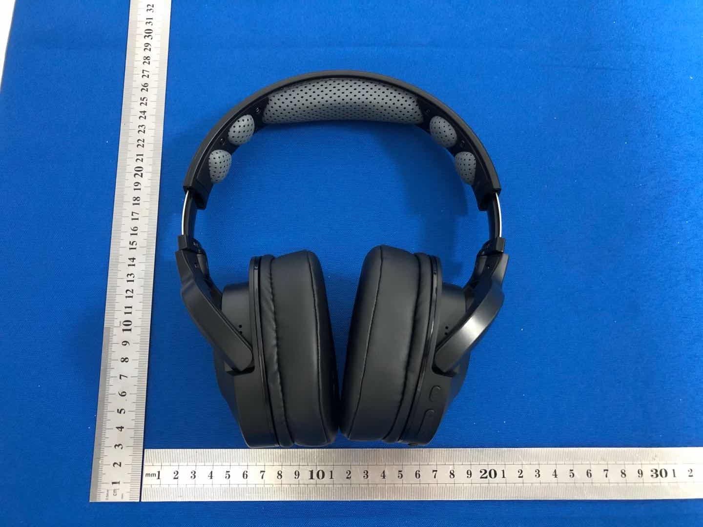
Click to zoom
Application Details
- Equipment Class
- DSS - Part 15 Spread Spectrum Transmitter
- Date of Grant
- Oct 31, 2020
- Application Purpose
- Original Equipment
- Date of Application
- Oct 31, 2020
- Equipment Note
- Bluetooth headphone
- Frequency Range
- 2402.00000000 - 2480.00000000
- Country
- China
Documents & Files
Document Text
Text extracted from the exhibit documents filed with the FCC. Open a document above to read the original.
Users Manual
Distributed by : GuangDong Kotion Electronics tech Co,.Ltd AddRoom 101 ,Building 1,NO18 ,2nd Road Sanjiang Industrial Areas,HengLi Town,DongGuan City,GuangDong Province Te l+86-0755-8486-2587 400-9955-829 Q9 Portable detachable gaming headset English...........................................................................4-6 日本語............................................................................7-9 Français.........................................................................10-13 Pусский язык................................................................13-16 Deutsch..........................................................................17-20 L'italiano.........................................................................20-23 Español .........................................................................23-26 中文 产品类型 喇叭直径 喇叭阻抗 电池容量 电池类型 充电时间 蓝牙耳机 40mm 32Ω±15% 600mAh 聚合物锂电池 3小时 ≥20小时 10米无阻碍物 3.7V DC4.75V-5.5V 耳机/USB充电线/说明书/ Line IN 连接线 耳机附件 续航时间 传输距离 工作电压 充电电压 产品参数 连接蓝牙耳机 功能介绍 1. 拨打/接听/挂断电话键,暂停/播放键,电源键. 2.“+”音量+(下一曲) ,按一下为下一曲,长按不放为音量加,音量 加到最大时有低沉的提示音. 3.“-”音量-(上一曲) ,按一下为上一曲,长按不放为音量减,音量 减到最小时有低沉的提示音. 4. 指示灯. 5. 耳机壳LED灯开关键,短按1S. 6. USB充电接口. 7.蓝牙麦克风. 8.Line In 接口. 9.Line线三节插头,插在耳机Line接口上. 10.麦克风静音开关. 11.麦克风. 12.耳机音量调节键. 13.Line线四节插头,适用于手机、平板电脑、笔记本电脑等3.5mm 单插孔音频设备. 1 1.有线无线,自由切换; 2.无线模式: 听音乐、 手机、 打电话、 看电影、 运动,请开启蓝牙模式。 3.有线模式: Xbox one、 PS4、 游戏手柄、 电脑、 平板电脑,请插入麦克风连接线。 4.横向90度自适应贴合耳壳,360度全包式耳罩,20度纵向自适应包裹,24h舒适透气佩戴。 适用环境 2 1.开机:在关机状态,长按 (3S 左右),发出“Power ON”提示音,指示灯红蓝交替闪烁; 2.配对:在开机状态,打开手机或其他设备上的蓝牙功能,并进行搜索或扫描,此时设备上搜索到附近蓝牙设备,点 PHOINIKAS Q9耳机进入配对,指示灯5S闪烁一次,配对成功。 3.正常播放模式:指示灯每隔5秒闪烁一次 ; 4.未连接成功模式:指示灯每隔5S闪烁两次,10分钟后自动关机,耳壳LED灯需手动关闭。 5.关机:在开机状态,长按 (3S ),发出“Power OFF”提示声音进入关机状态,指示灯灭,耳壳LED灯需手动关 闭。 1 7 6 5 4 2 3 8 1.当检测到有Line In 插入时,转换到Line In 模式,蓝牙断开; 2.低电压报警,当电压低于3.3V时,发出嘀嘀的报警声。插入DC电源时保持工作状态; 3.欠压自动关机,当电压低于3.1V时,蓝牙自动关闭整机,重新充电后,按开机键重新开机; 4.充电智能管理,插入DC电源供电,双色LED指示灯红灯亮,充电完成,红灯熄灭; 5.当有电话拨入时,音乐自动断开,短按 键,接通电话。结束通话,短按 键一次,音乐自动接入,当拨入电 话方结束通话时,无需任何操作,音乐自动接入; 6.当在听音乐时,连续短按 两次,可重拨最近一次来电记录或者去电记录。 其他功能 8 9 10 11 13 12 蓝牙耳机与电脑之间的连接 1.在电脑没有自带蓝牙功能的情况下,请另外购置蓝牙适配器; 2.将蓝牙适配器插入电脑的USB接口,按照电脑的提示安装好蓝牙适配器驱动,具体操作: A)打开控制面板,选择“声音和音频设备” B)选择“音频”选项卡,在“播放设备”和“录音设备”里头选择你刚装好的蓝牙声音设备设置好之后选择确 定,退出即可。 C)再选择“语音”选项卡,同样也是在“播放设备”里头选择你刚装好的蓝牙声音设备,设置好之后选择确定, 退出即可。 English Product type Speaker diameter: Speaker impedance Battery capacity Battery type Charging time Dynamic Earphone 40mm 32Ω±15% 600mah Polymer Lithium Battery 3 Hours ≥20 hours 10 m 3.7V DC4.75V-5.5V Headset/ Usb Charging Cable/line In Connection Cable Headset Accessories Duration time Transmission distance Working voltage Charging voltage Product parameters Connect to Bluetooth earphone Function introduction 1.Connected: continuously press button (about 3s), when heard sounding of “Power ON” and indicator lights' lighting red and blue color separately, turn on the bluetooth function of your mobile or other's equipment, and start to search or scan, when searched "PHOINIKAS Q9" and connected, the indicator lights will shine every five seconds,connected successfully. 2.Connected: when indicator lights’ lighting red and blue color separately, turn on the bluetooth function of your mobile or other’s equipment, and start to search or scan, when searched "PHOINIKAS Q9" and connected, the indicator lights will shine every five seconds, connected successfully. 3. Playing mode:indicator lights will shine one time every five seconds. 4.Unconnected mode: indicator lights will shine two times every five seconds, and after 10 minutes, earphone will turn off automatically. (The LED lights need to be closed by manual) 5.Turn off : continuously press button ( about 3s), when heard sounding of “Power Off”, indicator lights will be off . (The LED lights need to be closed by manual) 1. Dial/Answer/Hang up button; Pause/Play button Power button; . 2Volume + (next song), press once to next song,long press and not release to increase volume, and when volume comes to maximum, there will be deep tone; 3. - Volume - (previous song), press once to previous song, llong press and not release to reduce volume, and when volume comes to minimum, there will be deep tone. 4. Indicator light . 5. LED light on-off button 6. USB charging interface 7. MIC 8. Line in jack. 9. Line cable triple plug, insert in headset Line interface; 10. One mute button 11. Microphone 12. Slide voice controllor 13. Line quadri plug, applies to the 3.5 quadrupole single jack audio device such as mobile phone, tablet PC, notebook computer, etc. 3.打开蓝牙管理软件,同时按住蓝牙耳机上的功能键5秒左右,当两种颜色的指示灯快速交替闪烁时,表明蓝牙耳机 已处于配对状态,只有在这种情况下,蓝牙适配器才有可能搜索到蓝牙耳机; 4.单击“我的蓝牙”,选择“搜索蓝牙设备”来搜索周边的蓝牙设备,如蓝牙耳机等; 5.如果搜索到附近有蓝牙设备的话,被搜索到的设备就会列出; 6.在搜索到设备上点右键,然后再选择“配对”; 7.在弹出的对话框里输入“0000”作为配对码; 8.若电脑自带蓝牙适配器,并且安装驱动和软件后,你先开始搜索,若搜寻到蓝牙耳机,可直接连接,试一下蓝牙耳 机,如果有声,则设置成功。 1.手机无法搜素到蓝牙耳机? A)确认蓝牙耳机是否开机(如开机,蓝红指示灯交替闪烁) B)如果确认已开机仍然无法搜索到,请重启蓝牙和手机。 2.蓝牙耳机和手机连接之后总是断线或是有杂音? A)蓝牙电量不足,需要尽快给蓝牙耳机充电; B)手机和蓝牙之间有阻碍或距离超出信号接收距离,请不要用手捂住蓝牙,为了保持信号的连续稳定性,请尽量保 持蓝牙和手机在同一方向。 3.其他蓝牙手机用户是否会听到我的通话内容? 耳机与蓝牙手机配对,会建立仅供这两个蓝牙设备使用的专用链接路线,根据耳机所采用的蓝牙技术,第三方是不 容易监听到通话内容的,而且蓝牙无线信号的射频功率远远小于普通的移动电话,所以这些信号很难被第三方侦查 到。 4.当手机与蓝牙耳机超出有效距离后会怎样? 当手机与蓝牙耳机超出有效距离后,蓝牙耳机与手机的连接会自动断开,当回到有效距离内时,耳机会自动与手机 连接,不需要任何设置,但是部分手机不支持该项功能,需要在设置列表内找到蓝牙设备选择连接即可。 5.如何给蓝牙耳机充电? A)将充电器插头插进耳机中,将充电器带有释放标签的一面朝下,耳机的正面朝上; B)将充电器的另一端插进电源插座中,充电时,耳机的指示器亮起直至充电结束,第一次充电时间大约需要8个小 时,以后充电3小时左右; C)当充电结束时(指示灯关闭),从电源插座中取下充电器,按充电器插头上的释放键,将充电器从耳机中取下。 (注:您在驾驶车辆时,可用原装的车载电源充电器给蓝牙耳机充电) 异常情况解决方案 1.为了避免损伤你的听力,请限制你在高音量下使用耳机的时间,并将音量设定在一个安全的水平。音量越高,安全 聆听时间便越短; 2.身处有潜在危险的场所时,请暂停使用耳机,为防止损坏或出现故障; 3.请不要将耳机暴露在过高温度的场所,例如加热设施附近或受阳关直接照射的汽车内; 4.请不要将耳机浸入水中; 5.请不要使用任何含酒精氨,进行清洁。如有需要,请使用软布进行清洁; 6.请不要将耳机的储存在温度低于-15度或者高于35度的地方,在低温条件下,电池的寿命可能会缩短; 7.请使用指定的USB充电设备。(充电电压DC4.75V-5.5V ) 重要事项 1 7 6 5 4 2 3 8 43 1.The mobile phone can’t search the Bluetooth headset? A) Confirm if Bluetooth headset is power on or off (if power on, blue and red indicator light flash alternately) B) If it is power on and still can’t search, please reboot Bluetooth and mobile phone. 2.After connecting the Bluetooth headset…
Text truncated - open the document above for the full version.
Cover Letter(s)
Zhong Tian Ding Sheng (Shenzhen) Industrial Co., Ltd Model Difference 2020-10-11 EUT NAME: Bluetooth headphone FCC ID: 2AXQO-Q9 MODEL : Q9,B3520 All the model are the same circuit and RF module, except model names. . Regards Sincerely Client’s signature Client’s name / title : Beijun Liu / Manager Contact information / address: Room 1920, South China Development Center No. 1 Huanan Avenue, Pinghu Street, Longgang District Shenzhen Guangdong Province i i
External Photos
External Photos
ID Label/Location Info
Label & label location Size:40*20mm Bluetooth headphone FCC ID: 2AXQO-Q9 This device complies with part 15 of the FCC Rules. Operation is subject to the following two conditions: (1) This device may not cause harmful interference, and (2) This device must accept any interference received, including interference that may cause undesired operation. Label location
Internal Photos
Internal Photos Antenna
RF Exposure Info
RF EXPOSURE EVALUATION METHOD FCC ID: 2AXQO-Q9 SAR Test Exclusion Thresholds for 100 MHz – 6 GHz and ≤ 50 mm Approximate SAR Test Exclusion Power Thresholds at Selected Frequencies and Test Separation Distances are illustrated in the following Table. The 1-g and 10-g SAR test exclusion thresholds for 100 MHz to 6 GHz at test separation distances ≤ 50 mm are determined by: [(max. power of channel, including tune-up tolerance, mW)/(min. test separation distance, mm)] · [√f(GHz)] ≤ 3.0 for 1-g SAR and ≤ 7.5 for 10-g extremity SAR,where f(GHz) is the RF channel transmit frequency in GHz Power and distance are rounded to the nearest mW and mm before calculation The result is rounded to one decimal place for comparison The test exclusions are applicable only when the minimum test separation distance is ≤ 50 mm and for transmission frequencies between 100 MHz and 6 GHz. When the minimum test separation distance is < 5 mm, a distance of 5 mm is applied to determine SAR test exclusion. BT-EDR max possible output power (PK,conducted):4±1dbm 0dBi logarithmic terms convert t o numeric result is nearly 1 5dbm=3.16mW 2402MHz [(max. power of channel, including tune-up tolerance, mW)/(min. test separation distance,mm)] · [√f(GHz)]=3.16/5*√2.402 =0.98≤3.0 Modulation Frequency (MHz) Output Power (dBm) Max Antenna Gain (dBi) GFSK 2402 0.67 0 GFSK 2441 0.90 0 GFSK 2480 0.84 0 Pi/4 DQPSK 2402 2.83 0 Pi/4 DQPSK 2441 3.06 0 Pi/4 DQPSK 2480 2.99 0 8DPSK 2402 3.33 0 8DPSK 2441 3.57 0 8DPSK 2480 3.43 0 Threshold at which no SAR required is 10mw and ≤ 3.0 for 1-g SAR, Separation distance is 5mm. 2441MHz [(max. power of channel, including tune-up tolerance, mW)/(min. test separation distance,mm)] · [√f(GHz)]= 3.16/5*√2.441=0.99≤3.0 Threshold at which no SAR required is 10mw and ≤ 3.0 for 1-g SAR, Separation distance is 5mm. 2480 MHz [(max. power of channel, including tune-up tolerance, mW)/(min. test separation distance,mm)] · [√f(GHz)]=3.16 /5*√2.48=0.10≤3.0 Threshold at which no SAR required is 10mw and ≤ 3.0 for 1-g SAR, Separation distance is 5mm. Conclusion: No SAR is required.
Test Report
No.:BCTC/RF-EMC-005 Page: 1 of 70 Edition:A.1 TEST REPORT Report No.: BCTC2009000498E Applicant: Zhong Tian Ding Sheng (Shenzhen) Industrial Co., Ltd Product Name: Bluetooth headphone Model/Type Ref.: Q9 Tested Date: Sep. 07, 2020 to Sep. 15, 2020 Issued Date: Sep. 15, 2020 Shenzhen BCTC Testing Co., Ltd. Report No.: BCTC2009000498E No.:BCTC/RF-EMC-005 Page: 2 of 70 Edition:A.1 FCC ID : 2AXQO-Q9 The test report is effective only with both signature and specialized stamp.This result(s) shown in this report refer only to the sample(s) tested. Without written approval of Shenzhen BCTC Testing Co., Ltd, this report can’t be reproduced except in full.The tested sample(s) and the sample information are provided by the client. Product Name: Bluetooth headphone Trademark: N/A Model/Type Ref.: Q9 B3520 Prepared For: Zhong Tian Ding Sheng (Shenzhen) Industrial Co., Ltd Address: Room 1920, South China Development Center No. 1 Huanan Avenue, Pinghu Street, Longgang District Shenzhen, Guangdong Province, China Manufacturer: GuangDong Kotion Electronics tech Co,.Ltd Address: Room 101 ,Building 1,NO18 ,2nd Road Sanjiang Industrial Areas,HengLi Town,DongGuan City,GuangDong Province Prepared By: Shenzhen BCTC Testing Co., Ltd. Address: 1-2F, East of B Building, Pengzhou Industrial, Fuyuan 1st Road, Qiaotou Community, Fuyong Street, Bao’an District, Shenzhen, China Sample Received Date: Sep. 07, 2020 Sample tested Date: Sep. 07, 2020 to Sep. 15, 2020 Issue Date: Sep. 15, 2020 Report No.: BCTC2009000498E Test Standards FCC Part15.247 ANSI C63.10-2013 Test Results PASS Remark: This is Bluetooth Classic radio test report. Tested by: Approved by: Sam zeng/Project Handler Zero Zhou/Reviewer Report No.: BCTC2009000498E No.:BCTC/RF-EMC-005 Page: 3 of 70 Edition:A.1 TABLE OF CONTENT Test Report Declaration Page 1. VERSION ............................................................ 5 2. TEST SUMMARY ..................................................... 6 3. MEASUREMENT UNCERTAINTY ....................................... 7 4. PRODUCT INFORMATION AND TEST SETUP ........................... 8 4.1 Product Information ..................................................... 8 4.2 Test Setup Configuration ................................................ 8 4.3 Support Equipment ..................................................... 9 4.4 Channel List ........................................................... 9 4.5 Test Mode ............................................................ 10 4.6 table of parameters of text software setting ................................ 10 5. TEST FACILITY AND TEST INSTRUMENT USED ........................ 11 5.1 Test Facility ........................................................... 11 5.2 Test Instrument Used .................................................. 11 6. CONDUCTED EMISSIONS ............................................ 13 6.1 Block Diagram Of Test Setup ........................................... 13 6.2 Limit ................................................................. 13 6.3 Test procedure ........................................................ 13 6.4 EUT operating Conditions .............................................. 13 6.5 Test Result ........................................................... 14 7. RADIATED EMISSIONS .............................................. 16 7.1 Block Diagram Of Test Setup ........................................... 16 7.2 Limit ................................................................. 17 7.3 Test procedure ........................................................ 18 7.4 EUT operating Conditions .............................................. 19 7.5 Test Result ........................................................... 20 8. RADIATED BAND EMISSION MEASUREMENT AND RESTRICTED BANDS OF OPERATION .......................................................... 24 8.1 Block Diagram Of Test Setup ........................................... 24 8.2 Limit ................................................................. 24 8.3 Test procedure ........................................................ 25 8.4 EUT operating Conditions .............................................. 25 8.5 Test Result ........................................................... 26 9. CONDUCTED EMISSION ............................................. 27 9.1 Block Diagram Of Test Setup ........................................... 27 9.2 Limit ................................................................. 27 9.3 Test procedure ........................................................ 27 9.4 Test Result ........................................................... 28 10. 20 DB BANDWIDTH .................................................. 37 10.1 Block Diagram Of Test Setup .......................................... 37 10.2 Limit ................................................................ 37 10.3 Test procedure ....................................................... 37 Report No.: BCTC2009000498E No.:BCTC/RF-EMC-005 Page: 4 of 70 Edition:A.1 10.4 Test Result .......................................................... 38 11. MAXIMUM PEAK OUTPUT POWER .................................... 43 11.1 Block Diagram Of Test Setup .......................................... 43 11.2 Limit ................................................................ 43 11.3 Test procedure ....................................................... 43 11.4 Test Result .......................................................... 44 12. HOPPING CHANNEL SEPARATION ................................... 49 12.1 Block Diagram Of Test Setup .......................................... 49 12.2 Limit ................................................................ 49 12.3 Test procedure ....................................................... 49 12.4 Test Result .......................................................... 50 13. NUMBER OF HOPPING FREQUENCY .................................. 55 13.1 Block Diagram Of Test Setup ..…
Text truncated - open the document above for the full version.
Test Report
Report No.: BCTC2009000498E No.:BCTC/RF-EMC-005 Page: 30 of 70 Edition:A.1 8DPSK Low Channel 8DPSK Middle Channel 8DPSK High Channel Report No.: BCTC2009000498E No.:BCTC/RF-EMC-005 Page: 31 of 70 Edition:A.1 GFSK Transmitting Band edge-left side GFSK Hopping Band edge-left side Report No.: BCTC2009000498E No.:BCTC/RF-EMC-005 Page: 32 of 70 Edition:A.1 GFSK Transmitting Band edge-right side GFSK Hopping Band edge-right side Report No.: BCTC2009000498E No.:BCTC/RF-EMC-005 Page: 33 of 70 Edition:A.1 Pi/4 DQPSK Transmitting Band edge-left side Pi/4 DQPSK Hopping Band edge-left side Report No.: BCTC2009000498E No.:BCTC/RF-EMC-005 Page: 34 of 70 Edition:A.1 Pi/4 DQPSK Transmitting Band edge-right side Pi/4 DQPSK Hopping Band edge-right side Report No.: BCTC2009000498E No.:BCTC/RF-EMC-005 Page: 35 of 70 Edition:A.1 8DPSK Transmitting Band edge-left side 8DPSK Hopping Band edge-left side Report No.: BCTC2009000498E No.:BCTC/RF-EMC-005 Page: 36 of 70 Edition:A.1 8DPSK Transmitting Band edge-right side 8DPSK Hopping Band edge-right side Report No.: BCTC2009000498E No.:BCTC/RF-EMC-005 Page: 37 of 70 Edition:A.1 10. 20 DB BANDWIDTH 10.1 Block Diagram Of Test Setup 10.2 Limit N/A 10.3 Test procedure 1. Set RBW = 30kHz. 2. Set the video bandwidth (VBW) ≥ 3 x RBW. 3. Detector = Peak. 4. Trace mode = max hold. 5. Sweep = auto couple. 6. Allow the trace to stabilize. 7. Measure the maximum width of the emission that is constrained by the frequencies associated with the two outermost amplitude points (upper and lower frequencies) that are attenuated by 6 dB relative to the maximum level measured in the fundamental emission. . Report No.: BCTC2009000498E No.:BCTC/RF-EMC-005 Page: 38 of 70 Edition:A.1 10.4 Test Result Temperature: 26°C Relative Humidity: 54% Test Voltage : DC 3.7V Remark N/A Modulation Test Channel Bandwidth(MHz) GFSK Low 1.031 GFSK Middle 1.031 GFSK High 1.031 Pi/4 DQPSK Low 1.357 Pi/4 DQPSK Middle 1.345 Pi/4 DQPSK High 1.351 8DPSK Low 1.348 8DPSK Middle 1.349 8DPSK High 1.345 Test plots GFSK Low Channel Report No.: BCTC2009000498E No.:BCTC/RF-EMC-005 Page: 39 of 70 Edition:A.1 GFSK Middle Channel GFSK High Channel Report No.: BCTC2009000498E No.:BCTC/RF-EMC-005 Page: 40 of 70 Edition:A.1 Pi/4 DQPSK Low Channel Pi/4 DQPSK Middle Channel Report No.: BCTC2009000498E No.:BCTC/RF-EMC-005 Page: 41 of 70 Edition:A.1 Pi/4 DQPSK High Channel 8DPSK Low Channel Report No.: BCTC2009000498E No.:BCTC/RF-EMC-005 Page: 42 of 70 Edition:A.1 8DPSK Middle Channel 8DPSK High Channel Report No.: BCTC2009000498E No.:BCTC/RF-EMC-005 Page: 43 of 70 Edition:A.1 11. MAXIMUM PEAK OUTPUT POWER 11.1 Block Diagram Of Test Setup 11.2 Limit FCC Part15 (15.247) , Subpart C Section Test Item Limit Frequency Range (MHz) Result 15.247(b)(1) Peak Output Power 0.125 watt or 21dBm 2400-2483.5 PASS 11.3 Test procedure 1. Remove the antenna from the EUT and then connect a low RF cable from the antenna port to the spectrum. 2. Set the spectrum analyzer: RBW = 3MHz. VBW = 3MHz. Sweep = auto; Detector Function = Peak. 3. Keep the EUT in transmitting at lowest, medium and highest channel individually. Record the max value. Report No.: BCTC2009000498E No.:BCTC/RF-EMC-005 Page: 44 of 70 Edition:A.1 11.4 Test Result Temperature: 26°C Relative Humidity: 54% Test Voltage : DC 3.7V Remark: N/A Modulation Test Channel Output Power (dBm) Limit (dBm) GFSK Low 0.67 21 GFSK Middle 0.90 21 GFSK High 0.84 21 Pi/4 DQPSK Low 2.83 21 Pi/4 DQPSK Middle 3.06 21 Pi/4 DQPSK High 2.99 21 8DPSK Low 3.33 21 8DPSK Middle 3.57 21 8DPSK High 3.43 21 Test plots GFSK Low Channel Report No.: BCTC2009000498E No.:BCTC/RF-EMC-005 Page: 45 of 70 Edition:A.1 GFSK Middle Channel GFSK High Channel Report No.: BCTC2009000498E No.:BCTC/RF-EMC-005 Page: 46 of 70 Edition:A.1 Pi/4 DQPSK Low Channel Pi/4 DQPSK Middle Channel Report No.: BCTC2009000498E No.:BCTC/RF-EMC-005 Page: 47 of 70 Edition:A.1 Pi/4 DQPSK High Channel 8DPSK Low Channel Report No.: BCTC2009000498E No.:BCTC/RF-EMC-005 Page: 48 of 70 Edition:A.1 8DPSK Middle Channel 8DPSK High Channel Report No.: BCTC2009000498E No.:BCTC/RF-EMC-005 Page: 49 of 70 Edition:A.1 12. HOPPING CHANNEL SEPARATION 12.1 Block Diagram Of Test Setup 12.2 Limit Frequency hopping systems shall have hopping channel carrier frequencies separated by a minimum of 25 kHz or the 20 dB bandwidth of the hopping channel, whichever is greater. Alternatively, frequency hopping systems operating in the 2400-2483.5 MHz band may have hopping channel carrier frequencies that are separated by 25 kHz or two-thirds of the 20 dB bandwidth of the hopping channel, whichever is greater, provided the systems operate with an output power no greater than 0.125W. 12.3 Test procedure 1. Remove the antenna from the EUT and then connect a low RF cable from the antenna port to the spectrum. 2. Set the spectrum analyzer: RBW = 30kHz. VBW = 100kHz , Span = 2.0MHz. Sweep = auto; Detector Function = Peak. Trace = Max hold. 3. Allow the trace to stabilize. Use the marker-delta function to determine the separation between the peaks of the adjacent channels. The limit is specified in one of the subparagraphs of this Section Submit this plot. Report No.: BCTC2009000498E No.:BCTC/RF-EMC-005 Page: 50 of 70 Edition:A.1 12.4 Test Result Modulation Test Channel Separation (MHz) Limit(MHz) Result GFSK Low 1.004 0.687 PASS GFSK Middle 1.002 0.687 PASS GFSK High 1.000 0.687 PASS Pi/4 DQPSK Low 1.000 0.905 PASS Pi/4 DQPSK Middle 1.000 0.897 PASS Pi/4 DQPSK High 0.994 0.901 PASS 8DPSK Low 1.008 0.899 PASS 8DPSK Middle 0.994 0.899 PASS 8DPSK High 0.994 0.897 PASS Test plots GFSK Low Channel
Test Report
Report No.: BCTC2009000498E No.:BCTC/RF-EMC-005 Page: 51 of 70 Edition:A.1 GFSK Middle Channel GFSK High Channel Report No.: BCTC2009000498E No.:BCTC/RF-EMC-005 Page: 52 of 70 Edition:A.1 Pi/4 DQPSK Low Channel Pi/4 DQPSK Middle Channel Report No.: BCTC2009000498E No.:BCTC/RF-EMC-005 Page: 53 of 70 Edition:A.1 Pi/4 DQPSK High Channel 8DPSK Low Channel Report No.: BCTC2009000498E No.:BCTC/RF-EMC-005 Page: 54 of 70 Edition:A.1 8DPSK Middle Channel 8DPSK High Channel Report No.: BCTC2009000498E No.:BCTC/RF-EMC-005 Page: 55 of 70 Edition:A.1 13. NUMBER OF HOPPING FREQUENCY 13.1 Block Diagram Of Test Setup 13.2 Limit Frequency hopping systems in the 2400-2483.5 MHz band shall use at least 15 channels. 13.3 Test procedure 1. Remove the antenna from the EUT and then connect a low RF cable from the antenna port to the spectrum. 2. Set the spectrum analyzer: RBW = 100kHz. VBW = 300kHz. Sweep = auto; Detector Function = Peak. Trace = Max hold. 3. Allow the trace to stabilize. It may prove necessary to break the span up to sections. in order to clearly show all of the hopping frequencies. The limit is specified in one of the subparagraphs of this Section. 4. Set the spectrum analyzer: Start Frequency = 2.4GHz, Stop Frequency = 2.4835GHz. Sweep=auto; Report No.: BCTC2009000498E No.:BCTC/RF-EMC-005 Page: 56 of 70 Edition:A.1 13.4 Test Result Test Plots: 79 Channels in total GFSK Pi/4 DQPSK Report No.: BCTC2009000498E No.:BCTC/RF-EMC-005 Page: 57 of 70 Edition:A.1 8DPSK Report No.: BCTC2009000498E No.:BCTC/RF-EMC-005 Page: 58 of 70 Edition:A.1 14. DWELL TIME 14.1 Block Diagram Of Test Setup 14.2 Limit Frequency hopping systems in the 2400-2483.5 MHz band shall use at least 15 channels. The average time of occupancy on any channel shall not be greater than 0.4 seconds within a period of 0.4 seconds multiplied by the number of hopping channels employed. Frequency hopping systems may avoid or suppress transmissions on a particular hopping frequency provided that a minimum of 15 channels are used. 14.3 Test procedure 1. Remove the antenna from the EUT and then connect a low RF cable from the antenna port to the spectrum. 2. Set spectrum analyzer span = 0. Centred on a hopping channel; 3. Set RBW = 1MHz and VBW = 3MHz.Sweep = as necessary to capture the entire dwell time per hopping channel. Set the EUT for DH5, DH3 and DH1 packet transmitting. 4. Use the marker-delta function to determine the dwell time. If this value varies with different modes of operation (e.g.. data rate. modulation format. etc.). repeat this test for each variation. The limit is specified in one of the subparagraphs of this Section. Submit this plot(s). Report No.: BCTC2009000498E No.:BCTC/RF-EMC-005 Page: 59 of 70 Edition:A.1 14.4 Test Result DH5 Packet permit maximum 1600 / 79 / 6 hops per second in each channel (5 time slots RX, 1 time slot TX). DH3 Packet permit maximum 1600 / 79 / 4 hops per second in each channel (3 time slots RX, 1 time slot TX). DH1 Packet permit maximum 1600 / 79 /2 hops per second in each channel (1 time slot RX, 1 time slot TX). So, the Dwell Time can be calculated as follows: DH5:1600/79/6*0.4*79*(MkrDelta)/1000 DH3:1600/79/4*0.4*79*(MkrDelta)/1000 DH1:1600/79/2*0.4*79*(MkrDelta)/1000 Remark: Mkr Delta is once pulse time. Modulation Channel Data Packet pulse time(ms) Dwell Time(s) Limits(s) GFSK Middle DH1 0.405 0.130 0.4 DH3 1.698 0.272 0.4 DH5 2.940 0.314 0.4 Pi/4DQPSK Middle 2DH1 0.412 0.132 0.4 2DH3 1.698 0.272 0.4 2DH5 2.970 0.317 0.4 8DPSK Middle 3DH1 0.412 0.132 0.4 3DH3 1.704 0.273 0.4 3DH5 2.970 0.317 0.4 Report No.: BCTC2009000498E No.:BCTC/RF-EMC-005 Page: 60 of 70 Edition:A.1 Test Plots GFSK DH1 Middle Channel GFSK DH3 Middle Channel Report No.: BCTC2009000498E No.:BCTC/RF-EMC-005 Page: 61 of 70 Edition:A.1 GFSK DH5 High Middle Channel Pi/4DQPSK DH1 Middle Channel Report No.: BCTC2009000498E No.:BCTC/RF-EMC-005 Page: 62 of 70 Edition:A.1 Pi/4DQPSK DH3 Middle Channel Pi/4DQPSK DH5 Middle Channel Report No.: BCTC2009000498E No.:BCTC/RF-EMC-005 Page: 63 of 70 Edition:A.1 8DPSK DH1 Middle Channel 8DPSK DH3 Middle Channel Report No.: BCTC2009000498E No.:BCTC/RF-EMC-005 Page: 64 of 70 Edition:A.1 8DPSK DH5 Middle Channel Report No.: BCTC2009000498E No.:BCTC/RF-EMC-005 Page: 65 of 70 Edition:A.1 15. ANTENNA REQUIREMENT 15 .1 Limit 15.203 requirement: For intentional device, according to 15.203: an intentional radiator shall be designed to ensure that no antenna other than that furnished by the responsible party shall be used with the device. 15.2 Test Result The EUT antenna is PCB antenna, fulfill the requirement of this section. Report No.: BCTC2009000498E No.:BCTC/RF-EMC-005 Page: 66 of 70 Edition:A.1 16. EUT PHOTOGRAPHS EUT Photo 1 EUT Photo 2 Report No.: BCTC2009000498E No.:BCTC/RF-EMC-005 Page: 67 of 70 Edition:A.1 EUT Photo 3 Report No.: BCTC2009000498E No.:BCTC/RF-EMC-005 Page: 68 of 70 Edition:A.1 17. EUT TEST SETUP PHOTOGRAPHS Conducted emissions Report No.: BCTC2009000498E No.:BCTC/RF-EMC-005 Page: 69 of 70 Edition:A.1 Radiated Measurement Photos Report No.: BCTC2009000498E No.:BCTC/RF-EMC-005 Page: 70 of 70 Edition:A.1 STATEMENT 1.The equipment lists are traceable to the national reference standards. 2.The test report can not be partially copied unless prior written approval is issued from our lab. 3.The test report is invalid without stamp of laboratory. 4.The test report is invalid without signature of person(s) testing and authorizing. 5.The test process and test result is only related to the Unit Under Test. 6.The quality system of our laboratory is in accordance with ISO/IEC17025. 7.If there is any objection to report, the client should inform issuing laboratory within 15 days from the date of receiving test report. Address: 1-2F, East of B Building, Pengzhou Industrial Park, Fuyuan 1st Road, Qiaotou, Fuyong Street, Ba o'an District,Shenzhen,Guangdong,China TEL:400-788-9558 P. C.: 518103 FAX:0755-33229357 Website:http://www.bctc-lab.com E-Mail:[email protected] ※※※※※ END ※※※※※
Test Setup Photos
Shenzhen BCTC Testing Co., Ltd. Report No.: BCTC2009000498E 1. EUT TEST SETUP PHOTOGRAPHS Spurious emissions Te s t Report Tel: 400-788-9558 Web: https://www.bctc-lab.com BCTC/RF-EMC-0 07 Ver.:A.0 Page 1 of 2 Shenzhen BCTC Testing Co., Ltd. Report No.: BCTC2009000498E Conducted emissions ※※※※※ END OF REPORT ※※※※※ Te s t Report Tel: 400-788-9558 Web: https://www.bctc-lab.com BCTC/RF-EMC-0 07 Ver.:A.0 Page 2 of 2
Contact Information
Applicant
Beijun Liu
Test Firm
Shenzhen BCTC Testing Co., Ltd.Sally He
[email protected]15999690624
Technical Specifications
| # | Rule Parts | Frequency Range | Power Output |
|---|---|---|---|
| 1 | 15C | 2.40 GHz - 2.48 GHz | 2.28 mW |
Other Applications from Zhong Tian Ding Sheng (Shenzhen) Industrial Co., Ltd
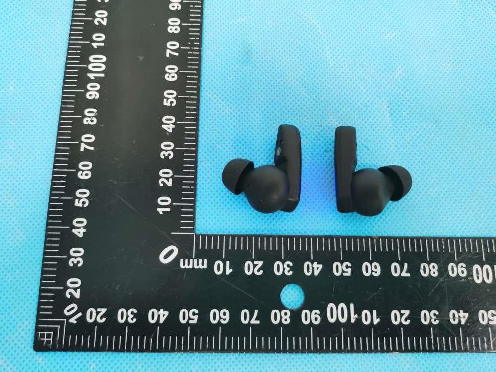
2AXQO-Q15
Jun 21, 2022TWS Wireless Earbuds
Equipment Class
DXX - Part 15 Low Power Communication Device Transmitter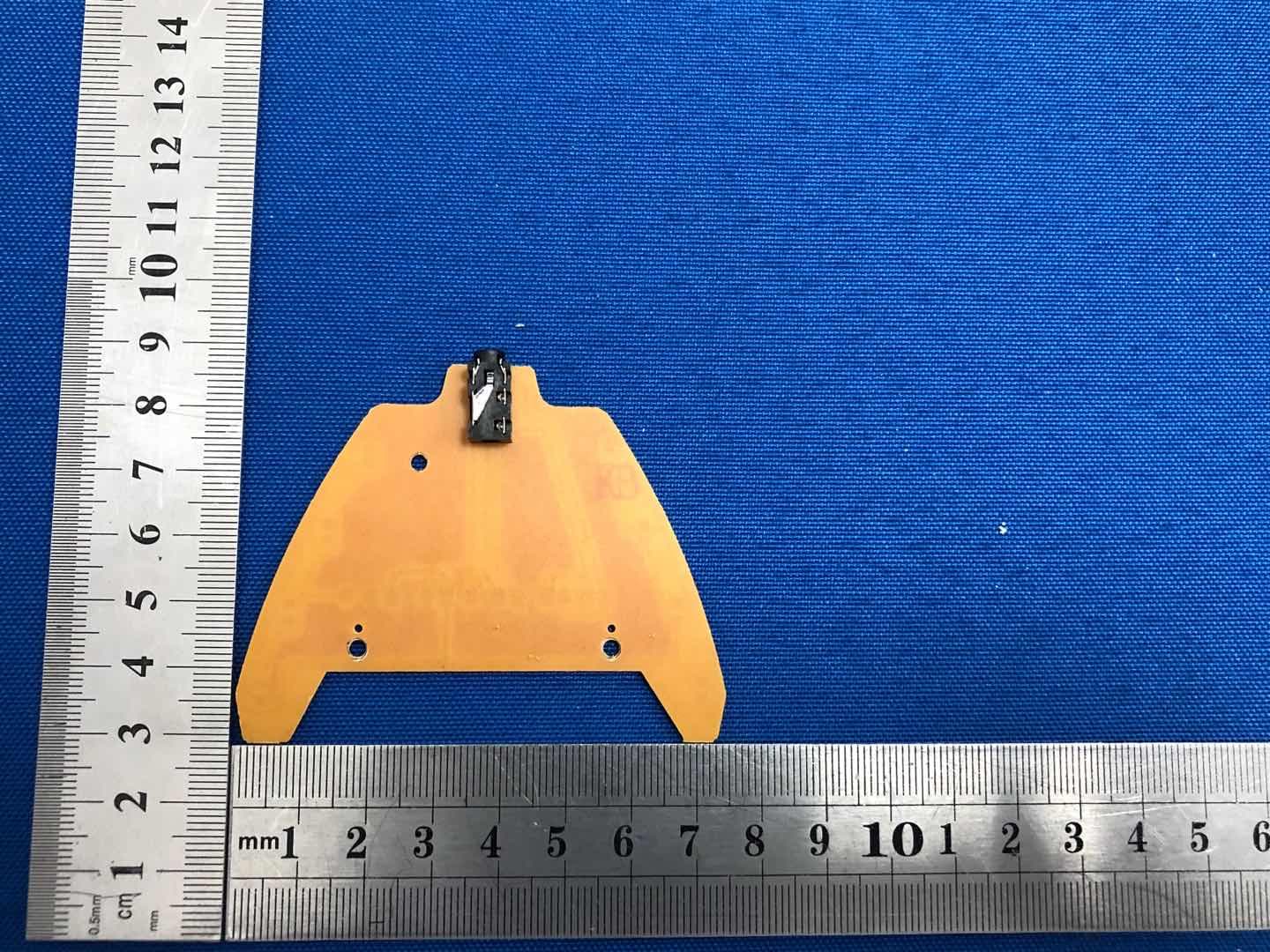
2AXQO-Q10
Oct 31, 2020Bluetooth headphone
Equipment Class
DSS - Part 15 Spread Spectrum Transmitter