2AXU3CC2500A1SCC2500A1S RF Module
Shenzhen Jinghua Displays Electronics Co., Ltd.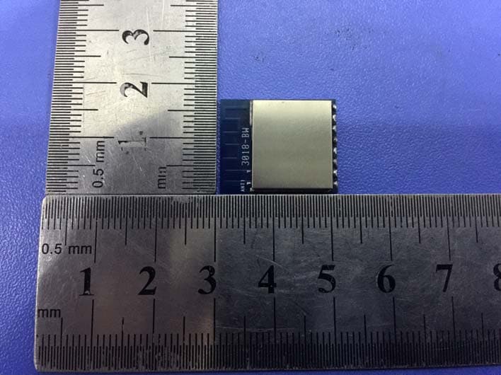
Click to zoom
Application Details
- Equipment Class
- DXX - Part 15 Low Power Communication Device Transmitter
- Date of Grant
- Mar 05, 2021
- Application Purpose
- Original Equipment
- Date of Application
- Mar 04, 2021
- Equipment Note
- CC2500A1S RF Module
- Frequency Range
- 2414.50000000 - 2449.50000000
- Country
- China
Documents & Files
Document Text
Text extracted from the exhibit documents filed with the FCC. Open a document above to read the original.
Users Manual
FINAL SPECIFICATION CC2500A1S RF Module REV:A1 PAGE 1 OF 7 DOCUMENT NUMBER AND REVISION CC2500-A1 RF Module REV:A1 DOCUMENT TITLE: SPECIFICATION OF RF Module CUSTOMER PART NO. Product Name CC2500A1S RF Module MODEL NUMBER CC2500A1S SAMPLE LOT NO. CUSTOMER APPROVAL DATE PRELIMINARY SPECIFICATION FINAL SPECIFICATION AND SAMPLE Shenzhen Jinghua Displays Electronics Co., Ltd. 4 th floor, 2 nd building, Jinghua displays Park, No.3 Liuhe Road, Liuyue Community, Henggang Street, Longgang District, Shenzhen China Tel: 86-755-82442519, 82487795 Fax: 86-755-82262610 86-755-82441596, 82448287 DEPARTMENT NAME SIGNATURE DATE PREPARED BY HuangXiangli CHECKED BY / APPROVED BY Yu Hao FINAL SPECIFICATION CC2500A1S RF Module REV:A1 PAGE 2 OF 7 URL: www.china-lcd.com DOCUMENT REVISION HISTORY: DOCUMENT REVISION DATE DESCRIPTION CHANGED BY A 2020.09.30 First Issue. HuangXiangli FINAL SPECIFICATION CC2500A1S RF Module REV:A1 PAGE 3 OF 7 CONTENTS Page No. 1. GENERAL DESCRIPTION 4 2. MECHANICAL SPECIFICATIONS 4 3. INTERFACE SIGNALS 5 4. ABSOLUTE MAXIMUM RATINGS 6 5. ELECTRICAL SPECIFICATIONS 7 FINAL SPECIFICATION CC2500A1S RF Module REV:A1 PAGE 4 OF 7 Specification of CC2500 RF Module 1. GENERAL DESCRIPTION The CC2500 module is a low cost and highly integrated 2.4GHz RF transceiver designed for very low power wireless applications. These pre-certified RF modules, working in the license free ISM band of 2.4GHz MHz can be easily integrated into your application, thereby reducing development time and cost. 2. MECHANICAL SPECIFICATIONS The mechanical detail is shown in Fig. 1 and Table 1 as below: Table 1 Parameter Specifications Unit Outline dimensions 20.80(L) x 18.20(W) x0.8(H) mm Figure 1(a): Module’s outline FINAL SPECIFICATION CC2500A1S RF Module REV:A1 PAGE 5 OF 7 3. INTERFACE SIGNALS SPI interface assignment : Pin No Symbol Function Remark 1 VCC Power 1.8V-3.6V 2 GND Power Ground 3 SI Digital Input Serial configuration interface, data input 4 SCLK Digital Input Serial configuration interface, clock input 5 SO Digital Onput Serial configuration interface, data output. 6 GNDO2 Digital Output Digital output pin for general use: Test signals/ FIFO status signals/Clear Channel Indicator/ Clock output, down-divided from XOSC/Serial output RX data 7 GNDO0 Digital I/O Digital output pin for general use: Test signals/ FIFO status signals/Clear Channel Indicator/ Clock output, down-divided from XOSC/Serial output RX data/ Serial input TX data 8 CSN Digital Input Serial configuration interface, chip select FINAL SPECIFICATION CC2500A1S RF Module REV:A1 PAGE 6 OF 7 4. ABSOLUTE MAXIMUM RATINGS Item Symbol Unit Min Max Note Power voltage VCC V -0.3 +3.6 1 Voltage on any digital pin V -0.3 VDD+0.3 , max 3.6 1 Voltage ramp-up rate VCC kV/μs 120 1 Input RF level dBm +10 1 Operation Temperature Topr ºC -40 +85 3 Notes 1、If used beyond the absolute maximum ratings, the product may be permanently damaged. It is strongly recommended that the device be used within the electrical characteristics in normal operations. If exposed to the condition not within the electrical characteristics, it may affect the reliability of the device. 2、The operating temperature is defined as the temperature range where the products operation is guaranteed. All the contents of electrical and optical specifications are guaranteed under the room temperature condition. FINAL SPECIFICATION CC2500A1S RF Module REV:A1 PAGE 7 OF 7 5. ELECTRICAL SPECIFICATIONS Operating Conditions : Parameter Sym. Min Typ. Max Unit Operating temperature Topr -40 85 ºC Operating supply voltage VCC 1.8 3.6 V General Characteristics : Ta = 25°C Item Min Ty p Max Unit Condition/Note Frequency range 2414.5 2449.35 MHz Data rate 1.2 500 kbps FSK 1.2 250 kbps GFSK and OOK 26 500 kbps (Shaped)MSK(also known as differential offset QPSK) Optional Manchester encoding(halves the data rate) Rx Current 15 mA Receive sensitivity Data rate=1.2kbps -10 6 dBm RF output Max.power 0 dBm PM3 Current Power down mode 0.4 uA FINAL SPECIFICATION CC2500A1S RF Module REV:A1 PAGE 8 OF 7 FCC Statement This device complies with part 15 of the FCC rules. Operation is subject to the following two conditions: (1) thi s device may not cause harmful interference, and (2) this device must accept any interference received, incl uding interference that may cause undesired operation. Changes or modifications not expressly approved by the party responsible for compliance could void the user’s authority to operate the equipment. NOTE: This equipment has been tested and found to comply with the limits for a Class B digital device, pursua nt to part 15 of the FCC Rules. These limits are designed to provide reasonable protection against harmful inte rference in a residential installation. This equipment generates uses and can radiate radio frequency energy a nd, if not installed and used in accordance with the instructions, may cause harmful interference to radio com munications. However, there is no guarantee that interference will not occur in a particular installation. If this equipment does cause harmful interference to radio or television reception, which can be determined by turn ing the equipment off and on, the user is encouraged to try to correct the interference by one or more of the following measures: ‐ Reorient or relocate the receiving antenna. ‐ Increase the separation between the equipment and receiver. ‐Connect the equipment into an outlet on a circuit different from that to which the receiver is connected. ‐Consult the dealer or an experienced radio/TV technician for help important announcement Important Note: In the event that these conditions cannot be met (for example certain laptop configurations or co-location with another transmitter), then the FCC authorization is no longer considered valid and the FCC ID cannot be used on the final product. In these circumstances, the OEM integrator will be responsible for re-evaluating the end product (including the transmitter) and obtaining a separate…
Text truncated - open the document above for the full version.
Cover Letter(s)
CONFIDENTIALITY REQUEST for Certification Service in USA Federal Communication Commission Equipment Authorization Division, Application Processing Branch 7435 Oakland Mills Road Columbia, MD 21046 Date:<2021-2-8> Pursuant to Paragraphs §0.457 and 0.459 of the Commission’s Rules (47 C.F.R.) and Section §552(b)(4) of the Freedom of Information Act, we requests confidentiality for the following products: FCC ID Model name 2AXU3CC2500A1S CC2500A1S For the product stated above, we request that the following information be held confidential; Exhibits Long-Term Confidentiality Short-Term Confidentiality Short-Term Confidentiality Days External Photos Internal Photos Block Diagram Schematics Test Setup Photos User’s Manual Parts List Tune Up Operational Descriptions The long-term confidentiality exhibits contain our trade secrets and proprietary information that could be of benefit to our competitors. The short-term confidentiality on the basis of ensuring that business sensitive information remains confidential until the actual marketing of our new device. If you have any questions, please feel free to contact me at the address shown below. Sincerely, Name/Title: Tingyan Wang/Laboratory Engineer Company: Shenzhen Jinghua Displays Electronics Co., Ltd. Address: Jinghua Displays Park, No.3 Liuhe Road, Longgang District Shenzhen China Phone: 0755 8213 1561 Fax: 0755 8226 2610 E-Mail: [email protected]
Cover Letter(s)
Shenzhen Jinghua Displays Electronics Co., Ltd. Jinghua Displays Park, No.3 Liuhe Road, Longgang District Shenzhen China Federal Communications Commission Authorization and Evaluation Division Equipment Authorization Branch 7435 Oakland Mills Road Columbia, MD 21046 2021-2-8 To whom it may concern: We, Shenzhen Jinghua Displays Electronics Co., Ltd. the undersigned, hereby authorize Eurofins Product Service GmbH to act on our behalf in all matters relating to applications for equipment authorization FCC ID: 2AXU3CC2500A1S including the signing of all documents related to these matters. Any and all acts carried out by Eurofins Product Service GmbH on our behalf shall have the same effect as acts of our own. We also hereby certify that no party to this application is subject to a denial of benefits, including FCC benefits, pursuant to Section 5301 of the Anti-Drug Abuse Act of 1988, 21 U.S.C. 862. Sincerely, Name/Title: Tingyan Wang/Laboratory Engineer Company: Shenzhen Jinghua Displays Electronics Co., Ltd. Address: Jinghua Displays Park, No.3 Liuhe Road, Longgang District Shenzhen China Phone: 0755 8213 1561 Fax: 0755 8226 2610 E-Mail: [email protected]
Cover Letter(s)
Shenzhen Jinghua Displays Electronics Co., Ltd. Jinghua Displays Park, No.3 Liuhe Road, Longgang District Shenzhen China Module Approval Request Letter 2021-2-8 To: Federal Communications Commission Authorization and Evaluation Division 7435 Oakland Mills Road Columbia, MD Subjects: Module Approval Request Letter The Device,FCC ID: 2AXU3CC2500A1S, is seeking FCC authorization as a modular transmitter. The EUT meets the requirement for modular approval as detailed in FCC Public Notice DA 00-1407. Compliance to each of the requirement is described below: (a) The radio elements must have the radio frequency circuitry be shielded. Physical/discrete and tuning capacitors may be located external to the shield, but must be on the module assembly. Yes the module with a shield. (b) The module shall have buffered modulation/data input(s) (if such inputs are provided) to ensure that the module will comply with the requirements set out in the applicable RSS standard under conditions of excessive data rates or over-modulation. Yes. (c) The module shall have its own power supply regulation on the module. This is to ensure that the module will comply with the requirements set out in the applicable standard regardless of the design of the power supplying circuitry in the host device which houses the module. The modular has an onboard 3.3V regulator(Support UART (3.3V TTL level) interface). (d) The module shall comply with the provisions for external power amplifiers and antennas detailed in this standard. The equipment certification submission shall contain a detailed description of the configuration of all antennas that will be used with the module. The modular has a External antenna which comply with the antenna requirement of Section 15.203. (e) The module shall be tested for compliance with the applicable standard in a stand-alone configuration, i.e. the module must not be inside another device during testing. The modular was tested in a standalone configuration apart from host units. (f) The module shall comply with the Category I equipment labeling requirements and CFR § 15.212(a)(1)(vi). The modular has its own FCC ID number. (g) The module shall comply with any applicable FCC RF exposure requirement which are based on the intended use/configurations. Not applicable,(Because the modular application FCC part 15.249 rules) (h) The modular transmitter complies with all applicable FCC rules. Instructions for maintaining compliance are given in the user instructions. Yes If you have any questions, please feel free to contact us at the address shown below Sincerely, Name/Title: Tingyan Wang/Laboratory Engineer Company: Shenzhen Jinghua Displays Electronics Co., Ltd. Address: Jinghua Displays Park, No.3 Liuhe Road, Longgang District Shenzhen China Phone: 0755 8213 1561 Fax: 0755 8226 2610 E-Mail: [email protected]
External Photos
Page: 3 of 6 FCC ID: 2AXU3CC2500A1S & IC: 26955-CC2500A1S TB-RF-074-1.0 Appendix III EUT Photographs Photo 1 Appearance of EUT Photo 2 Appearance of EUT Antenna
ID Label/Location Info
Page: 1 of 6 FCC ID: 2AXU3CC2500A1S & IC: 26955-CC2500A1S TB-RF-074-1.0 AppendixIFCC ID&IC Label FCC ID: 2AXU3CC2500A1S IC: 26955-CC2500A1S HVIN/Model: CC2500A1S Page: 2 of 6 FCC ID: 2AXU3CC2500A1S & IC: 26955-CC2500A1S TB-RF-074-1.0 Appendix II ID&IC Label Location ID&IC LOCATION
Internal Photos
Page: 3 of 6 FCC ID: 2AXU3CC2500A1S & IC: 26955-CC2500A1S TB-RF-074-1.0 Appendix III EUT Photographs Photo 1 Appearance of EUT Photo 2 Appearance of EUT Antenna Page: 4 of 6 FCC ID: 2AXU3CC2500A1S & IC: 26955-CC2500A1S TB-RF-074-1.0 Photo 3 Appearance of EUT
Test Report
Shenzhen Toby Technology Co., Ltd. Report No.: TB-FCC176406 Page: 1 of 35 TB-RF-074-1.0 1/F.,Building 6, Rundongsheng Industrial Zone, Longzhu, Xixiang, Bao'an District, Shenzhen, Guangdong, China Tel: +86 75526509301 Fax: +86 75526509195 FCC Radio Test Report FCC ID: 2AXU3CC2500A1S Report No. : TB-FCC176406 Applicant : Shenzhen Jinghua Displays Electronics Co., Ltd. Equipment Under Test (EUT) EUT Name : CC2500A1S RF Module Model No. : CC2500A1S Series Model No. : N/A Brand Name : N/A Sample ID : TBBJ-20200909-12-1#&TBBJ-20200909-12-1# Receipt Date : 2020-09-28 Test Date : 2020-09-29 to 2021-01-19 Issue Date : 2021-01-20 Standards : FCC Part 15, Subpart C 15.249 Test Method : ANSI C63.10: 2013 Conclusions : PASS In the configuration tested, the EUT complied with the standards specified above, The EUT technically complies with the FCC requirements Test/Witness Engineer : Rebeca Engineer Supervisor : Ivan Su Approved & Authorized : Ray Lai This report details the results of the testing carried out on one sample. The results contained in this test report do not relate to other samples of the same product. The manufacturer should ensure that all products in series production are in conformity with the product sample detailed in the report. Report No.: TB-FCC176406 Page: 2 of 35 TB-RF-074-1.1 Contents CONTENTS ............................................................................................................................................. 2 1. GENERAL INFORMATION ABOUT EUT ............................................................................. 5 1.1 Client Information ................................................................................................................. 5 1.2 General Description of EUT (Equipment Under Test) ................................................... 5 1.3 Block Diagram Showing the Configuration of System Tested ...................................... 6 1.4 Description of Support Units .............................................................................................. 6 1.5 Description of Test Mode .................................................................................................... 6 1.6 Description of Test Software Setting ................................................................................ 7 1.7 Measurement Uncertainty .................................................................................................. 8 1.8 Test Facility ........................................................................................................................... 8 2. TEST SUMMARY ....................................................................................................................... 9 3. TEST SOFTWARE ..................................................................................................................... 9 4. TEST EQUIPMENT .................................................................................................................. 10 5. CONDUCTED EMISSION TEST ........................................................................................... 11 5.1 Test Standard and Limit .................................................................................................... 11 5.2 Test Setup ........................................................................................................................... 11 5.3 Test Procedure ................................................................................................................... 11 5.4 EUT Operating Mode ........................................................................................................ 12 5.5 Deviation From Test Standard ......................................................................................... 12 5.6 Test Data ............................................................................................................................. 12 6. RADIATED EMISSION TEST ................................................................................................ 13 6.1 Test Standard and Limit .................................................................................................... 13 6.2 Test Setup ........................................................................................................................... 14 6.3 Test Procedure ................................................................................................................... 15 6.4 EUT Operating Condition ................................................................................................. 16 6.5 Deviation From Test Standard ......................................................................................... 16 6.6 Test Data ............................................................................................................................. 16 7. BANDWIDTH TEST ................................................................................................................. 17 7.1 Test Setup ........................................................................................................................... 17 7.2 Test Procedure ................................................................................................................... 17 7.3 EUT Operating Condition ................................................................................................. 17 7.4 Deviation From Test Standard ......................................................................................... 17 7.5 Test Data ............................................................................................................................. 17 8. ANTENNA REQUIREMENT ................................................................................................... 18 8.1 Standard Requirement ...................................................................................................... 18 8.2 Antenna Connected Construction ......................…
Text truncated - open the document above for the full version.
Test Setup Photos
Page: 5 of 6 FCC ID: 2AXU3CC2500A1S & IC: 26955-CC2500A1S TB-RF-074-1.0 Appendix IV EUT Test Photographs 15C Test Setup Photo of Setup for Radiated Emission (Above 1 GHz) Photo of Setup for Radiated Emission (Below 1 GHz) Page: 6 of 6 FCC ID: 2AXU3CC2500A1S & IC: 26955-CC2500A1S TB-RF-074-1.0 Photo of Setup for Conducted Emission
Contact Information
Applicant
Tingyan Wang(Laboratory Engineer)
Test Firm
Shenzhen Toby Technology Co., Ltd.Ray Lai
Technical Specifications
| # | Rule Parts | Frequency Range | Power Output |
|---|---|---|---|
| 1 | 15C | 2.41 GHz - 2.45 GHz | - |