2AXUT-UNI4260 GHz Radar Module
Augmented Radar Imaging, Inc.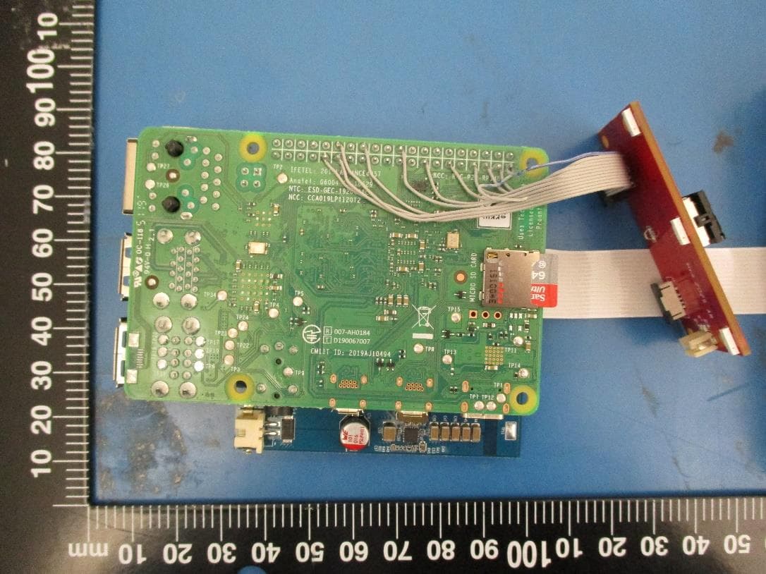
Click to zoom
Application Details
- Equipment Class
- DXX - Part 15 Low Power Communication Device Transmitter
- Date of Grant
- Dec 16, 2020
- Application Purpose
- Original Equipment
- Date of Application
- Dec 16, 2020
- Equipment Note
- 60 GHz Radar Module
- Frequency Range
- 60000.00000000 - 64000.00000000
- Country
- United States
Documents & Files
Document Text
Text extracted from the exhibit documents filed with the FCC. Open a document above to read the original.
Users Manual
QA-FR-175-A User’s Guide November 2020 Revision 1.0 ARI UNI42 60GHz Radar Module 1. Introduction The UNI42 radar module from Augmented Radar Imaging is an easy-to-use board that contains 60-GHz mmWave Radar transceiver with patch antennas etched on PCB and acts as a Radar front-end module. It can be used in various applications where object detection, distance measurement, or speed measurement are required. The radar module is equipped with 12-pin and 32-pin connectors to interface external peripherals and host boards so that the users can customize for their specific applications. 2. Hardware Features 2.1. Features Radar tuning frequency: 60-64GHz Number of Receivers: 4 Number of Transmitter: 3 Processing: MCU, FFT accelerator, DSP Memory: 1.75 MB Antenna: microstrip patch antenna Onboard temperature sensor 2.2. Interface Connectors There are two connectors on the UNI42 Radar module. They are used as interface to the host system and/or peripherals. The pins include power rails, SPI interface, I2C bus, and other miscellaneous signals. Pin Number Description Pin Number Description 1 3V3 2 DRV_INT_L 3 GND 4 I2C_SCL 5 I2C_SDA 6 RESET_L 7 SPI_CS_L 8 SPI_CLK 9 SPI_MISO 10 SPI_MOSI 11 5V 12 GND Table 1: J1 12-pin Connector Pinout QA-FR-175-A Pin Number Description Pin Number Description 1 3V3 2 5V 3 I2C_SDA 4 5V 5 I2C_SCL 6 GND 7 SPI_CS_L 8 TXD0 9 GND 10 RXD0 11 RESET_L 12 FAN_CTRL 13 PWR_DWN_L 14 GND 15 DRV_INT_L 16 SOP2 17 3V3 18 EN_3V 19 RADAR_NRST 20 GND 21 RXD4 22 RADAR_GPIO_0 23 NC 24 NC 25 NC 26 SPI_CLK 27 NC 28 NC 29 SPI_MISO 30 NC 31 SPI_MOSI 32 NC Table 2: J2 32-pin Connector Pinout 2.3. Onboard Antenna The UNI42 Radar module has built-in microstrip patch antennas for both transmitters and receivers. The antennas are connected directly to the Radar transceiver chip via microstrip transmission lines, and the connections are permanent. Per FCC regulation, the end user is prohibited from modifying any part of the antennas and the feed traces. 3. System Integration Considerations 3.1. Hardware Brief/general discussion on how end user could integrate this module with a host system, from HW perspective. 3.2. Software The module is configured by the host through commands sent over the UART port. Please consult with the module manufacturer for details. 3.3. Test Modes When the UNI42 Radar module is installed in a host, the host manufacturer may need to disable the module in order to perform certain tests such as FCC Part 15 Subpart B. In order to disable the transmitter, the following command should be issued to the module over the UART port: sensorStop To return the transmitter to its normal operating state, the following command should be issued to the module over the UART port: sensorStart QA-FR-175-A 4. Regulatory Compliance 4.1. Operational Considerations TheUNI42 Radar module is designed to transmit at power level that meets the FCC EIRP peak power requirement. The host manufacturer does not have the ability to adjust the output power. 4.2. RF Exposure Considerations In accordance to the EN 62311 RF exposure test on the Radar transceiver, a minimum separation distance of 20 centimeters should be maintained between the user and the UNI42 Radar module during operation. This equipment complies with FCC radiation exposure limits set forth for an uncontrolled environment. End users must follow the specific operating instructions for satisfying RF exposure compliance. This transmitter must be at least 20 cm from the user and must not be co-located or operating in conjunction with any other antenna or transmitter. The information in this guide may change without notice. The manufacturer assumes no responsibility for any errors that may appear in this guide This equipment complies with the IC RSS-102 radiation exposure limits set forth for an uncontrolled environment. This equipment should be installed and operated with a minimum distance of 20 cm between the radiator and your body. Énoncé d'exposition aux rayonnements: Cet équipement est conforme aux limites d'exposition aux rayonnements ioniques RSS-102 Pour un environnement incontrôlé. Cet équipement doit être installé et utilisé avec un Distance minimale de 20 cm entre le radiateur et votre corps. 4.3. Label and Compliance Information The UNI42 Radar module is shipped with FCC/IC ID label permanently affixed to its RF shield. The label is shown below: Figure 3: FCC/IC Label 4.4. Part 15 Subpart B Disclaimer The UNI42 Radar module is only authorized for FCC Part 15.255 and IC RSS-210 rules (intentional transmitter). While this module is also FCC Part 15b and/or IC ES-003 compliant (unintentional radiator), the end user must ensure the final host product still meets Part 15b and/or QA-FR-175-A IC ES-003 compliance through testing with the UNI42 module installed. 4.5. FCC Statements per 47 CFR §15.105 Class B Device Note: This equipment has been tested and found to comply with the limits for a Class B digital device, pursuant to part 15 of the FCC Rules. These limits are designed to provide reasonable protection against harmful interference when the equipment is operated in a commercial environment. This equipment generates, uses, and can radiate radio frequency energy and, if not installed and used in accordance with the instruction manual, may cause harmful interference to radio communications. Operation of this equipment in a residential area is likely to cause harmful interference in which case the user will be required to correct the interference at his own expense. per 47 CFR §15.19 This device complies with part 15 of the FCC Rules. Operation is subject to the following two conditions: (1) This device may not cause harmful interference, and (2) this device must accept any interference received, including interference that may cause undesired operation. per 47 CFR §15.21 The user’s manual or instruction manual for an intentional or unintentional radiator shall caution the user that changes or modifications not expressly ap…
Text truncated - open the document above for the full version.
Cover Letter(s)
QA-FR-172-A FCC Confidential Authorization November 2, 2020 FEDERAL COMMUNICATIONS COMMISSIONS Authorization and Evaluation Division 7435 Oakland Mills Road Columbia, MD 21046 Subject: Confidentiality Request regarding application for certification of FCC ID: 2AXUT-UNI42 In accordance with Sections 0.457 and 0.459 of the Commission’s Rules, Augmented Radar Imaging, Inc. hereby requests long-term confidential treatment of information accompanying this application as outlined below: Block Diagram Schematics Operation Description As well as short-term confidential (45 days) treatment of information accompanying this application as outlined below: Internal Photos User’s Manual External Photos Test Set-up Photos The above materials contain proprietary and confidential information not customarily released to the public. The public disclosure of these materials provides unjustified benefits to its competitors in the market. Sincerely, David Xu Principal RF Engineer Augmented Radar Imaging, Inc. 1680 Holt Avenue, Los Altos, CA 94024
Cover Letter(s)
QA-FR-175-A Modular Approval Letter November 2, 2020 FEDERAL COMMUNICATIONS COMMISSIONS Authorization and Evaluation Division 7435 Oakland Mills Road Columbia, MD 21046 Subject: Modular Approval Letter The Device, FCC ID: 2AXUT-UNI42, is seeking FCC authorization as a modular transmitter. The EUT meets the requirement for modular approval as detailed in FCC Public Notice DA 00-1407. Compliance to each of the requirements is described below: 1. The modular transmitter must have its own RF shielding. The radio elements of the module is covered by a shield. Please refer to User Guide for a photo of the device showing the RF shield. 2. The modular transmitter must have buffered modulation/data inputs. This module accepts a number of serial data inputs from the host system for proper operations of the Radar chip, and all inputs are buffered. 3. The modular transmitter must have its own power supply regulator. The module has multiple voltage regulators on board: 5V, 3.3V, 1.8V, 1.24V, and 1V. Please refer to the schematics in the submission package. 4. The modular transmitter must comply with the antenna requirement of section 15.203 and 15.204(c). The onboard antenna is permanently etched onto the PCB and connected to the transmitter via RF trace. Tampering with the antenna is prohibited. 5. The modular transmitter must be tested in a stand-alone configuration. The device is tested with supporting equipment such as computer. The emission from the device is recorder after emission from supporting equipment has been removed. Please refer to the test reports. 6. The modular transmitter must be labeled with its own FCC ID number. The module is labeled with FCC ID number and the label is affixed to the RF shield. Please refer to exhibition Label for FCC ID for the drawing in the User’s Guide. 7. The modular transmitter must comply with any specific rule or operating requirements and the manufacturer must provide adequate instruction along with the module to explain any such requirements. The device is compliant with all applicable FCC rules. Detailed instructions for maintaining compliance are given in the User’s Guide. 8. The modular transmitter must comply with any applicable RF exposure requirements. QA-FR-175-A The device is compliant with all applicable RF exposure requirements. RF Exposure is addressed in the RF Exposure exhibition section of the User’s Guide. Sincerely Yours, David Xu Principal RF Engineer Augmented Radar Imaging, Inc. 1680 Holt Avenue, Los Altos, CA 94024
External Photos
Augmented Radar Imaging, Inc. FCC ID: 2AXUT-UNI42; IC: 26578-UNI42 EUT External Photographs 1.1 EUT Front View 1.2 EUT Rear View Antenna Augmented Radar Imaging, Inc. FCC ID: 2AXUT-UNI42; IC: 26578-UNI42 1.3 EUT with Debug Board and Screen view 1.4 EUT with Debug Board Front View Augmented Radar Imaging, Inc. FCC ID: 2AXUT-UNI42; IC: 26578-UNI42 1.5 EUT with Debug Board Rear View
ID Label/Location Info
ARI UNI42 FCC/IC Label The UNI42 Radar module is shipped with FCC/IC ID label permanently affixed to its RF shield. The label is shown below: Figure 1 FCC/IC Label Figure 2 Label Location on RF Shield
Internal Photos
Augmented Radar Imaging, Inc. FCC ID: 2AXUT-UNI42; IC: 26578-UNI42 EUT Internal Photographs 1.1 EUT Internal View 1.2 EUT Internal View Zoom
Test Report
Note: This test report is prepared for the customer shown above and for the device described herein. It may not be duplicated or used in part without prior written consent from Bay Area Compliance Laboratories Corp. This report must not be used by the customer to claim product certification, approval, or endorsement by A2LA*, NIST, or any agency of the Federal Government. * This report may contain data that are not covered by the A2LA accreditation and are marked with an asterisk “*” (Rev.2) FCC PART 15, SUBPART C ISEDC RSS-210, ISSUE 10, DECEMBER 2019 TEST REPORT For Augmented Radar Imaging, Inc. 1680 Holt Ave, Los Altos, CA 94024, United States R e p o r t T y p e : O r i g i n a l R e p o r t P r o d u c t T y p e : R a d a r M o d u l e Prepared By: Zhao Zhao Test Engineer Report Number: R2010224-255 Report Date: 2020-11-12 Reviewed By: Simon Ma RF Supervisor Bay Area Compliance Laboratories Corp. 1274 Anvilwood Ave., Sunnyvale, CA 94089, USA Tel: (408) 732-9162, Fax: (408) 732 9164 FCC ID: 2AXUT-UNI42 IC: 26578-UNI42 Augmented Radar Imaging, Inc. FCC ID: 2AXUT-UNI42; IC: 26578-UNI42 Report Number: R2010224-255 Page 2 of 51 FCC Part 15C/ISEDC RSS-210 Test Report TABLE OF CONTENTS 1 General Description ..................................................................................................................................................... 5 1.1 Product Description for Equipment Under Test (EUT) ...................................................................................... 5 1.2 Objective ............................................................................................................................................................. 5 1.3 Related Submittal(s)/Grant(s) ............................................................................................................................. 5 1.4 Test Methodology ............................................................................................................................................... 5 1.5 Measurement Uncertainty ................................................................................................................................... 6 1.6 Test Facility Registrations .................................................................................................................................. 6 1.7 Test Facility Accreditations ................................................................................................................................ 6 2 System Test Configuration.......................................................................................................................................... 9 2.1 Justification ......................................................................................................................................................... 9 2.2 EUT Exercise Software....................................................................................................................................... 9 2.3 Equipment Modifications.................................................................................................................................... 9 2.4 Local Support Equipment ................................................................................................................................... 9 2.5 Support Equipment ........................................................................................................................................... 10 2.6 Interface Ports and Cabling ............................................................................................................................... 10 3 Summary of Test Results ............................................................................................................................................ 11 4 FCC §15.203 & ISEDC RSS-Gen §6.8 - Antenna Requirements ............................................................................ 12 4.1 Applicable Standards ........................................................................................................................................ 12 4.2 Antenna Description ......................................................................................................................................... 12 5 FCC §2.1091, §15.255(g) & ISEDC RSS-102 - RF Exposure ................................................................................... 13 5.1 Applicable Standards ........................................................................................................................................ 13 5.2 MPE Prediction ................................................................................................................................................. 14 5.3 MPE Results for FCC and IC ............................................................................................................................ 15 6 FCC §15.207 & ISED RSS-Gen §8.8 - AC Line Conducted Emissions ................................................................... 16 6.1 Applicable Standards ........................................................................................................................................ 16 6.2 Test Setup ......................................................................................................................................................... 16 6.3 Test Procedure .................................................................................................................................................. 16 6.4 Corrected Amplitude and Margin Calculation .................................................................................................. 17 6.5 Test Setup Block Diagram ................................................................................................................................ 17 6.6 Test Equipment List and Details ....................................................................…
Text truncated - open the document above for the full version.
Test Setup Photos
Augmented Radar Imaging, Inc. FCC ID: 2AXUT-UNI42; IC: 26578-UNI42 Annex A (Normative) - Test Setup Photographs 1.1 Radiated Spurious Emission 30MHz-1 GHz Front View 1.2 Radiated Spurious Emission 30MHz-1 GHz Rear View Augmented Radar Imaging, Inc. FCC ID: 2AXUT-UNI42; IC: 26578-UNI42 1.3 Radiated Spurious Emission 1-18 GHz Front View 1.4 Radiated Spurious Emission 1-18 GHz Rear View Augmented Radar Imaging, Inc. FCC ID: 2AXUT-UNI42; IC: 26578-UNI42 1.5 Radiated Spurious Emission 18-26.5 GHz Front View 1.6 Radiated Spurious Emission 18-26.5 GHz Rear View Augmented Radar Imaging, Inc. FCC ID: 2AXUT-UNI42; IC: 26578-UNI42 1.7 Radiated Spurious Emission 26.5-40 GHz Front View 1.8 Radiated Spurious Emission 26.5-40 GHz Rear View Augmented Radar Imaging, Inc. FCC ID: 2AXUT-UNI42; IC: 26578-UNI42 1.9 Radiated Spurious Emission above 40 GHz Front View 1.10 Radiated Spurious Emission above 40 GHz Rear View Augmented Radar Imaging, Inc. FCC ID: 2AXUT-UNI42; IC: 26578-UNI42 1.11 AC Line Conducted Emissions Front View 1.12 AC Line Conducted Emissions Side View
Contact Information
Applicant
David Xu
Test Firm
Bay Area Compliance Laboratories Corp.Lisa Tang
Technical Specifications
| # | Rule Parts | Frequency Range | Power Output |
|---|---|---|---|
| 1 | 15C | 60.00 GHz - 64.00 GHz | 7.60 mW |