Text extracted from the exhibit documents filed with the FCC. Open a document above to read the original.
NOTE: This equipment has been tested and found to comply with the limits for a Class B digital device, pursuant to part 15 of the FCC Rules. These limits aredesigned to provide reasonable protection against harmful interference in a residential installation. This equipment generates uses and can radiate radio frequency energy and, if not installed and used in accordance with the instructions, may cause harmful interference to radio communications. However, there is no guarantee that interference will not occur in a particular installation. If this equipment does cause harmful interference to radio or television reception, whichcan be determined by turning the equipment off and on, the user is encouraged totry to correct the interference by one or more of the following measures: - Reorient or relocate the receiving antenna. - Increase the separation between the equipment and receiver. -Connect the equipment into an outlet on a circuit different from that to which the receiver is connected. -Consult the dealer or an experienced radio/TV technician for help Changes or modifications not expressly approved by the party responsible for compliancecould void the user's authority to operate the equipment. This device complies with Part 15 of the FCC Rules. Operation is subject to the following two conditions: (1) this device may not cause harmful interference, and (2) this device must accept any interference received, including interference that may cause undesired operation.
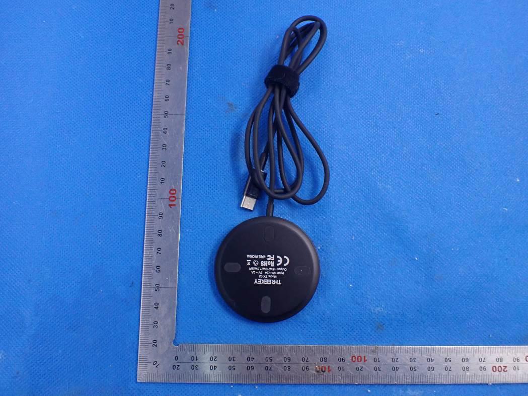
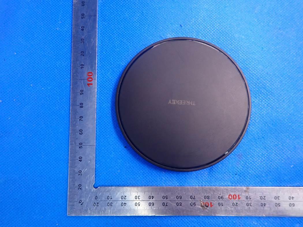
External Photos TOP VIEW OF EUT BOTTOM VIEW OF EUT FRONT VIEW OF EUT BACK VIEW OF EUT LEFT VIEW OF EUT RIGHT VIEW OF EUT VIEW OF EUT (PORT)
FCC ID Label Location FCC ID: 2AXWP-TK-01
Internal Photos OPEN VIEW OF EUT INTERNAL VIEW OF EUT-1 INTERNAL VIEW OF EUT-2 INTERNAL VIEW OF EUT-3 INTERNAL VIEW OF EUT-4 Antenna
Dongguan Sanqishi Technology Co.,Ltd Declaration concerning Antenna Specification It is hereby declared that the product Model No.: TK-01 FCC ID: 2AXWP-TK-01 fulfills the requirement in FCC test relating to the antenna type. The device specified above confirms to the FCC recommendations for internal antenna type(s) described below: 1. Type of antenna: Coil Antenna Frequency range: 110-205 kHz The mounting of the antenna is fixed to the radio module and no other antenna should be used. Company name: Dongguan Sanqishi Technology Co.,Ltd Address: Room 701, 101 Jinfenghuang Avenue, Fenggang Town, Dongguan, Guangdong, China Place: Dongguan city Date: 2020-11-20 Signature:
Page 1 of 14 RF Exposure Report Report No.: AGC11398201001FH03 APPLICATION PURPOSE : Original Equipment PRODUCT DESIGNATION : Wireless charger BRAND NAME : N/A MODEL NAME : TK-01 APPLICANT : Dongguan Sanqishi Technology Co.,Ltd DATE OF ISSUE : Nov. 13, 2020 STANDARD(S) : KDB680106 D01 RF Exposure Wireless Charging Base App v03 REPORT VERSION : V1.0 Attestation of Global Compliance(Shenzhen) Co., Ltd Report No.: AGC11398201001FH03 Page 2 of 14 REPORT REVISE RECORD Report Version Revise Time Issued Date Valid Version Notes V1.0 / Nov. 13, 2020 Valid Initial Release Report No.: AGC11398201001FH03 Page 3 of 14 TABLE OF CONTENTS 1. VERIFICATION OF CONFORMITY ............................................................................................................... 4 2. GENERAL INFORMATION ............................................................................................................................ 5 2.1. PRODUCT DESCRIPTION ..................................................................................................................... 5 3. DESCRIPTION OF TEST MODES................................................................................................................. 6 4. SYSTEM TEST CONFIGURATION ............................................................................................................... 6 5. TEST FACILITY ............................................................................................................................................. 7 6. RADIO FREQUENCY (RF) EXPOSURE TEST ............................................................................................. 8 6.1. LIMITS ..................................................................................................................................................... 8 6.2. TEST SETUP ........................................................................................................................................... 8 APPENDIX A: PHOTOGRAPHS OF TEST SETUP ......................................................................................... 11 Report No.: AGC11398201001FH03 Page 4 of 14 1. VERIFICATION OF CONFORMITY Applicant Dongguan Sanqishi Technology Co.,Ltd Address Room 701, 101 Jinfenghuang Avenue, Fenggang Town, Dongguan, Guangdong Manufacturer Shenzhen Joway Power Supply Co., Ltd. Address Floor 1-5 of Bldg 10th and Bldg 11th, Antuoshan High-Tech Industrial Park, Sha'er Community, Shajing Street, Bao'an District, Shenzhen Factory Shenzhen Joway Power Supply Co., Ltd. Address loor 1-5 of Bldg 10th and Bldg 11th, Antuoshan High-Tech Industrial Park, Sha'er Community, Shajing Street, Bao'an District, Shenzhen Product Designation Wireless charger Brand Name N/A Test Model: TK-01 Date of test Oct. 26, 2020 to Nov. 13, 2020 Deviation No any deviation from the test method Condition of Test Sample Normal Report Template AGCRT-US-BR/RF We hereby certify that: The above equipment was tested by Attestation of Global Compliance(Shenzhen) Co., Ltd. The test data, data evaluation, test procedures, and equipment configurations shown in this report were made in accordance with the procedures given in KDB680106 D01. The results of testing in this report apply to the product/system which was tested only. Prepared By Sky Dong (Project Engineer) Nov. 13, 2020 Reviewed By Max Zhang (Reviewer) Nov. 13, 2020 Approved By Forrest Lei (Authorized Officer) Nov. 13, 2020 Report No.: AGC11398201001FH03 Page 5 of 14 2. GENERAL INFORMATION 2.1.PRODUCT DESCRIPTION A major technical description of EUT is described as following Operation Frequency 110-205 kHz Test Frequency 145kHz Maximum field strength 52.75dBuV/m(PK)@3m Number of channels 1 Antenna Designation Coil Antenna (Met 15.203 Antenna requirement) Hardware Version V0.0 Software Version V0.0 Power Supply DC 9V by adapter Report No.: AGC11398201001FH03 Page 6 of 14 3. DESCRIPTION OF TEST MODES NO. TEST MODE DESCRIPTION 1 Wireless charging Mode(Full load) 2 Wireless charging Mode(Half load) 3 Wireless charging Mode(Null load) Note: 1. The mode 1 was the worst case and only the data of the worst case record in this report. 4. SYSTEM TEST CONFIGURATION Item Equipment Model No. ID or Specification Remark 1 Through Surface Wireless Charger ARC-H (LD) 2AXWP-TK-01 EUT 2 Adapter MX24Z1-1900940 DC 9V AE 3 Wireless Load N/A 10W AE Report No.: AGC11398201001FH03 Page 7 of 14 5. TEST FACILITY TEST EQUIPMENT LIST Description Manufacturer Model S/N Cal. Date Cal. Due Broadband Field Meter Narda Safety Test Solutions GmbH ELT-400 J-0004 May 25,2020 May 24,2021 Probe FHP Narda Safety Test Solutions GmbH 2300/90.10 J-0015 May 25,2020 May 24,2021 TestSite Attestation of Global Compliance(Shenzhen) Co., Ltd Location 1-2/F,Building19,JunfengIndustrialPark,ChongqingRoad,HepingCommunity,FuhaiSt reet,Bao'anDistrict,Shenzhen,Guangdong,China Designation Number CN1259 FCC Test Firm Registration Number 975832 A2LA Cert. No. 5054.02 Description Attestation of Global Compliance(Shenzhen) Co., Ltd is accredited by A2LA Report No.: AGC11398201001FH03 Page 8 of 14 6. RADIO FREQUENCY(RF) EXPOSURETEST 6.1. LIMITS For devices designed for typical desktop applications, such a wireless charging pads, RF exposure evaluation should be conducted assuming a user separation distance of 15 cm. E and H field strength measurements or numerical modeling may be used to demonstrate compliance. Measurements should be made from all sides and the top of the primary/client pair, with the 15 cm measured from the center of the probe(s) to the edge of the device. Emissions between 100 kHz to 300 kHz should be assessed versus the limits at 300 kHz in Table 1 of Section 1.1310: 614 V/m and 1.63 A/m. 6.2. TEST SETUP Note: Position A: Front of EUT; Position B: Left of EUT; Position C: back of EUT; Position D: Right of EUT; Position E: Top of EUT(20 cm measure distance); Report No.: AGC11398201001FH03 Page 9 of 14 6.3. TEST PROCEDURE The EUT was placed on a non-conductive table top and theโฆ
Text truncated - open the document above for the full version.
Page 1 of 29 FCC Test Report Report No.: AGC11398201001FE04 FCC ID : 2AXWP-TK-01 APPLICATION PURPOSE : Original Equipment PRODUCT DESIGNATION : Wireless charger BRAND NAME : N/A MODEL NAME : TK-01 APPLICANT : Dongguan Sanqishi Technology Co.,Ltd DATE OF ISSUE : Nov. 13, 2020 STANDARD(S) TEST PROCEDURE(S) : FCC Part 15 Rules REPORT VERSION : V1.0 Attestation of Global Compliance (Shenzhen) Co., Ltd Report No.: AGC11398201001FE04 Page 2 of 29 REPORT REVISE RECORD Report Version Revise Time Issued Date Valid Version Notes V1.0 / Nov. 13, 2020 Valid Initial Release Report No.: AGC11398201001FE04 Page 3 of 29 TABLE OF CONTENTS 1. VERIFICATION OF CONFORMITY ............................................................................................................... 4 2. GENERAL INFORMATION ............................................................................................................................ 5 2.1. PRODUCT DESCRIPTION ..................................................................................................................... 5 3. MEASUREMENT UNCERTAINTY ................................................................................................................. 6 4. DESCRIPTION OF TEST MODES ................................................................................................................. 7 5. SYSTEM TEST CONFIGURATION ............................................................................................................... 8 5.1. CONFIGURATION OF EUT SYSTEM ..................................................................................................... 8 5.2. EQUIPMENT USED IN EUT SYSTEM ..................................................................................................... 8 5.3. SUMMARY OF TEST RESULTS .............................................................................................................. 8 6. TEST FACILITY ............................................................................................................................................. 9 7. RADIATED EMISSION ................................................................................................................................. 10 7.1TEST LIMIT ............................................................................................................................................. 10 7.2. MEASUREMENT PROCEDURE ............................................................................................................ 11 7.3. TEST SETUP ......................................................................................................................................... 12 7.4. TEST RESULT ....................................................................................................................................... 13 8. 20DB BANDWIDTH ..................................................................................................................................... 16 8.1. MEASUREMENT PROCEDURE ........................................................................................................... 16 8.2. TEST SET-UP (BLOCK DIAGRAM OF CONFIGURATION) ................................................................... 16 8.3. MEASUREMENT RESULTS .................................................................................................................. 17 9. FCC LINE CONDUCTED EMISSION TEST ................................................................................................ 18 9.1. LIMITS OF LINE CONDUCTED EMISSION TEST ................................................................................ 18 9.2. BLOCK DIAGRAM OF LINE CONDUCTED EMISSION TEST .............................................................. 18 9.3. PRELIMINARY PROCEDURE OF LINE CONDUCTED EMISSION TEST ............................................ 19 9.4. FINAL PROCEDURE OF LINE CONDUCTED EMISSION TEST .......................................................... 19 9.5. TEST RESULT OF LINE CONDUCTED EMISSION TEST .................................................................... 20 APPENDIX A: PHOTOGRAPHS OF TEST SETUP ........................................................................................ 22 APPENDIX B: PHOTOGRAPHS OF EUT ....................................................................................................... 24 Report No.: AGC11398201001FE04 Page 4 of 29 1. VERIFICATION OF CONFORMITY Applicant Dongguan Sanqishi Technology Co.,Ltd Address Room 701, 101 Jinfenghuang Avenue, Fenggang Town, Dongguan, Guangdong Manufacturer Shenzhen Joway Power Supply Co., Ltd. Address Floor 1-5 of Bldg 10th and Bldg 11th, Antuoshan High-Tech Industrial Park, Sha'er Community, Shajing Street, Bao'an District, Shenzhen Factory Shenzhen Joway Power Supply Co., Ltd. Address loor 1-5 of Bldg 10th and Bldg 11th, Antuoshan High-Tech Industrial Park, Sha'er Community, Shajing Street, Bao'an District, Shenzhen Product Designation Wireless charger Brand Name N/A Test Model TK-01 Date of test Oct. 26, 2020 to Nov. 13, 2020 Deviation No any deviation from the test method Condition of Test Sample Normal Test Result Pass Report Template AGCRT-US-BR/RF We hereby certify that: The above equipment was tested by Attestation of Global Compliance (Shenzhen) Co., Ltd. The test data, data evaluation, test procedures, and equipment configurations shown in this report were made in accordance with the procedures given in ANSI C63.10 (2013) and the energy emitted by the sample EUT tested as described in this report is in compliance with Section 15.207, 15.209, 15.203 of the FCC Part 15, Subpart C Rules. The results of testing in this report apply to the product/system which was tested only. Prepared By Sky Dong (Project Engineer) Nov. 13, 2020 Reviewed By Max Zhang (Reviewer) Nov. 13, 2020 Approved By Forrest Lei (Authorized Officer) Nov. 13, 2020 Report No.: AGC11398201001FE04 Page 5 of 29 2. GENERAL INFORMATION 2.1. PRODUCT DESCRIPTโฆ
Text truncated - open the document above for the full version.
Test Setup Photos FCC RADIATED EMISSION TEST SETUP BELOW 1GHZ FCC LINE CONDUCTED EMISSION TEST SETUP
| # | Rule Parts | Frequency Range | Power Output |
|---|---|---|---|
| 1 | 15C | 0.11 MHz - 0.205 MHz | - |

Wireless charger
Equipment Class
DCD - Part 15 Low Power Transmitter Below 1705 kHz