FCCID.CO- FCC ID Database
HomeCompaniesEquipment ClassesSearch

© 2026 FCC ID Database. All rights reserved.

AboutContactData sourced from FCC public records
  1. Home/
  2. DTDS Technology Pvt Limited/
  3. 2AXXTDTDS-622LORAMO

2AXXTDTDS-622LORAMOLORA Module-DTDS-622

DTDS Technology Pvt Limited
LORA Module-DTDS-622 - FCC ID 2AXXTDTDS-622LORAMO - DTDS Technology Pvt Limited
Click to zoom

Application Details

Equipment Class
DSS - Part 15 Spread Spectrum Transmitter
Date of Grant
Nov 29, 2020
Application Purpose
Original Equipment
Date of Application
Nov 28, 2020
Equipment Note
LORA Module-DTDS-622
Frequency Range
902.30000000 - 914.90000000
Company
DTDS Technology Pvt Limited
Country
India

Documents & Files

Select a file to view

Users Manual

↗

Cover Letter(s)

↗
↗
↗

External Photos

↗

ID Label/Location Info

↗

Internal Photos

↗

RF Exposure Info

↗

Test Report

↗

Test Setup Photos

↗

Document Text

Text extracted from the exhibit documents filed with the FCC. Open a document above to read the original.

Users Manual

DTDS LoRa Module User Manual LoRa Module – DTDS-622 DTDS-622 Product Manual Page 2 DTDS2130001 Rev 1.2 User Manual October 2020 Contents Product Description .................................................................................................................................... 3 General Features ......................................................................................................................................... 3 Applications ................................................................................................................................................. 3 Package View .............................................................................................................................................. 4 Pin I/O Description and Serial Configuration .......................................................................................... 5 Connection Circuit ...................................................................................................................................... 6 Technical Specifications ............................................................................................................................. 7 Physical Dimensions ................................................................................................................................... 8 Notes ............................................................................................................................................................. 9 FCC Compliance Statement (USA) FCC ID: 2AXXTDTDS-622LORAMO Compliance Statements: This device complies with Part 15 of the FCC Rules. Operation is subject to the following two conditions: 1. This device may not cause harmful interference. 2. This device must accept any interference received, including, an interference that may cause undesired operation. Caution Statements: • Any changes or modifications not expressly approved by the party responsible for compliance could void the user’s authority to operate this equipment. • This equipment should be installed and operated with a minimum distance of 20 cm between the radiator and your body. This module is labelled with its own FCC ID. The end product using this module is required to display a label on itself referring to the enclosed module details. The final product must be labelled with the following: “Contains FCC ID: 2AXXTDTDS-622LORAM” The OEM using this product should not provide information to end user regarding installation or removal of this transmitter RF module or information to change RF related parameters in the user manual or by any means, with the end product. The OEM shall integrate the module as per the module Integration guidelines and grant condition. The OEM is responsible for ensuring compliance with the applicable FCC rules for the transmitters operating individually and simultaneously. DTDS-622 Product Manual Page 3 DTDS2130001 Rev 1.2 User Manual October 2020 Product Description DTDS LoRa-622 is a low cost, low power consumption long range solution for wireless communication. The module complies with both Class A and Class C LoRaWAN protocol specifications. It is suitable for Long Range sensor-based applications interfaced with an external host MCU. It also provides high interference immunity and meets all the LoRaWAN protocol specifications. General Features 1. TCXO enabled stable clock. 2. Operating Temperature range -40 °C to +85 °C. 3. AT Commands Interface over UART. 4. Low power consumption. 5. Assembly pads for easy PCB mounting. 6. Highly compact Form Factor of 15 x 26 x 5 mm. Applications 1. Water Meters 2. Energy Meters 3. Home Automation 4. Lighting Monitoring and Control 5. Environmental Sensors 6. Smart Cities 7. Other IoT Products DTDS-622 Product Manual Page 4 DTDS2130001 Rev 1.2 User Manual October 2020 Package View Figure 1- Top View of DTDS-622 Module DTDS-622 Product Manual Page 5 DTDS2130001 Rev 1.2 User Manual October 2020 Pin I/O Description and Serial Configuration Pin Number Pin Name Pin Type Pin Description 1 GND - Ground 2 GND - Ground 3 GND - Ground 4 GPIO/AN0 I/O Analog Input/GPIO 5 Reserved - Reserved for future use 6 Reserved - Reserved for future use 7 Reserved - Reserved for future use 8 Reserved - Reserved for future use 9 NC - No Connection 10 VDD_MAIN I Supply for the Main Board 11 Reserved - Reserved for future use 12 Reserved - Reserved for future use 13 NC - No Connection 14 GND - Ground 15 NC - No Connection 16 UART_TxD O AT Commands Transmit to Host 17 UART_RxD I AT Commands Receive from Host 18 NC - No Connection 19 GPIO/AN3 I/O Analog Input/GPIO 20 GPIO/AN2 I/O Analog Input/GPIO 21 GPIO/AN1 I/O Analog Input/GPIO 22 VDD_RF I Supply for the RF Module 23 GND - Ground 24 GND - Ground 25 ANT I/O Antenna Signal 26 GND - Ground Table 1 - Pin Description for DTDS-622 Module Configuration Items Value Baud rate 115200 bps Data bit 8 bits Parity bit None Stop bit 1 bit Flow control None Local echo back No Line terminator Transmission: CR+LF Reception: CR+LF Table 2 – Serial/ UART Configuration DTDS-622 Product Manual Page 6 DTDS2130001 Rev 1.2 User Manual October 2020 Connection Circuit Figure 2- Connection Diagram for User Application Note: Antenna does not form the scope of supply with the module. An external Antenna can be connected to the UFL connector available on the module or the Antenna output from the module can be extended to an SMA or any other type of connector on the host application board. The recommended Antenna is 50 Ohms terminated Taoglas T1.92.2113 Omnidirectional Antenna with a peak gain not exceeding 2.14 dBi in the bent configuration. DTDS-622 Product Manual Page 7 DTDS2130001 Rev 1.2 User Manual October 2020 Technical Specifications Parameters Typical Specifications Units Mechanical Specification Size 15(W) X 27(L) X 5(H) mm Package 26 pins, SMD - Electrical Specification Power Supply 3 – 3.7, 3.3 Typical V Standby Current < 4 mA Sleep Current ≈15 μA TX Cur…

Text truncated - open the document above for the full version.

External Photos

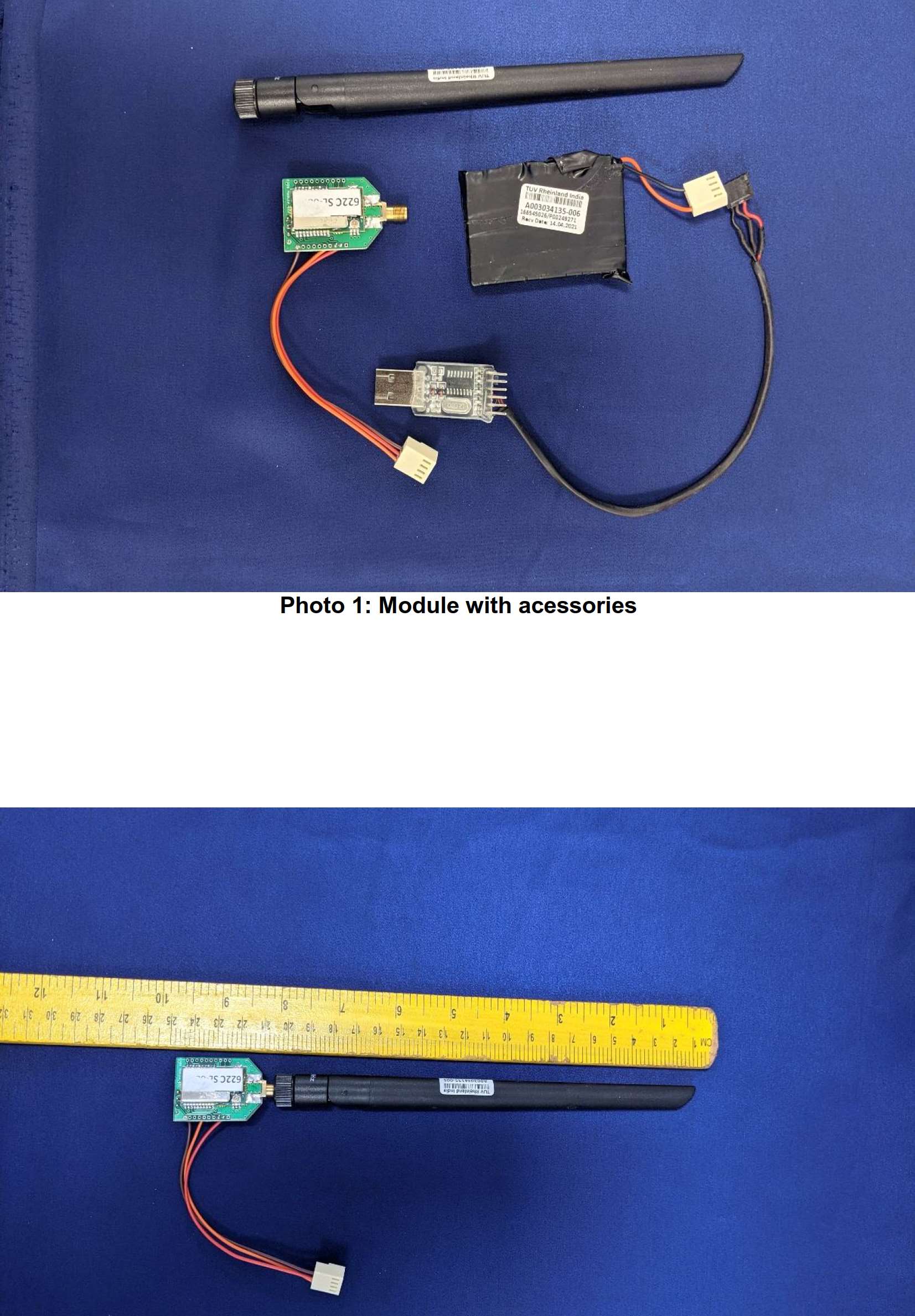
Produkte Products www.tuv.com EUT External Photos ReferenceTest Report No:ULRTC568820300000058F Seite 1 von 4 Page 1 of 4 EUT External Photo Photo 1: Module inside plastic enclosure Photo 3: Module connected to external antenna Produkte Products www.tuv.com EUT External Photos ReferenceTest Report No:ULRTC568820300000058F Seite 2 von 4 Page 2 of 4 Photo 6: Plastic Enclosure Open Photo 7: Module used with supporting board for testing purpose Produkte Products www.tuv.com EUT External Photos ReferenceTest Report No:ULRTC568820300000058F Seite 3 von 4 Page 3 of 4 Photo 8: Module used with supporting board for testing purpose Photo 8: Module and supporting board Produkte Products www.tuv.com EUT External Photos ReferenceTest Report No:ULRTC568820300000058F Seite 4 von 4 Page 4 of 4 Photo 8: battery connected to Module via supporting board and USB cable used for the configuration of module via supporting board

Internal Photos

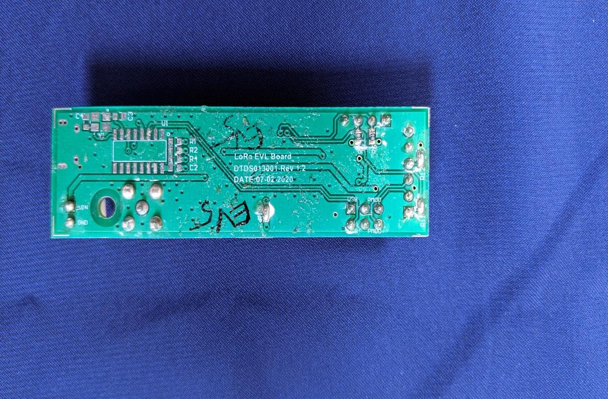
Produkte Products www.tuv.com EUT Internal Photos ReferenceTest Report No:ULRTC568820300000058F Seite 1 von 3 Page 1 of 3 EUT Internal Photo Photo 1: Module Front view Photo 2: Module Rear view Produkte Products www.tuv.com EUT Internal Photos ReferenceTest Report No:ULRTC568820300000058F Seite 2 von 3 Page 2 of 3 Photo 3: Module with shield Photo 4: Module Dimentional view Produkte Products www.tuv.com EUT Internal Photos ReferenceTest Report No:ULRTC568820300000058F Seite 3 von 3 Page 3 of 3 Photo 5: Module Dimentional view

RF Exposure Info

Produkte Products www.tuv.com ReferenceTest Report No:ULRTC568820300000058F Seite 1 von 2 Page 1 of 2 1 Radio Frequency Human Exposure Evaluation: 1.1 RF Exposure Measurement The limit for Maximum Permissible Exposure (MPE) specified in FCC 1.1310. The gain of the antennas used in the product is extracted from the Antenna data sheets provided and also the maximum total power input to the antenna is measured. Through the Friis transmission formula and the maximum gain of the antenna, we can calculate the distance, away from the product, where the limit of MPE is reached. Although the Friis Transmission formula is far field assumption, the calculated result of that is an over-prediction for near field power density. It is taken as worst case to specify the safety range. 1.2 RF Exposure Limit According to FCC 1.1310: The criteria listed in the following table shall be used to evaluate the environmental impact of the human exposure to radio-frequency (RF) radiation as specified in 1.1307 (b) showed in Table. F or ƒ = Frequency in MHz Produkte Products www.tuv.com ReferenceTest Report No:ULRTC568820300000058F Seite 2 von 2 Page 2 of 2 1.3 Assessment Conditions Protocol Frequency band (MHz) Maximum conducted output power in (dBm)* Tune-up tolerance Output power including tune-up tolerance (mW) Antenna gain in Linear Scale Power density (mw/cm2 ) Limit(mw/ cm2) Sub GHz 908.5 16.26 ±1 53.210 1.3212 0.01399 0.6056 *Note: Manufacturer declared TuneUp tollarance of ±1dB is considered in the calculation Antenna gain : Staight 1.21 dBi Friis Formula Friis Formula is used for assessment of power density. Friis Transmission Formula: Pd = (Pout * G) / (4*pi*r²) Where Pd = power density in mW/cm² Pout = output power to antenna in mW G = gain of antenna in linear scale Pi = 3.1416 r = Minimum distance between observation point and the center of radiator in cm If we know the maximum gain of the antenna and the total output power to the antenna, through calculation, we will know MPE value at distance 20cm (MPE evaluation performed with minimum separation distance from the User is 20cm).

Test Report

Prüfbericht – Produkte Test Report - Products Prüfbericht-Nr.: Test report no.: ULR-TC568820300000058F Auftrags-Nr.: Order no.: 166450461 0030 Seite 1 von 48 Page 1 of 48 Kunden-Referenz-Nr.: Client reference no.: NA Auftragsdatum: Order date: 2020-03-31 Auftraggeber: Client: DTDS Technology Private Ltd 4-4-82/22, Near Veera Reddy Nagar, Nacharam Main Road, Hyderabad - 500076 Prüfgegenstand: Test item: DTDS’s 622 Module for LoRa communication Bezeichnung / Serien -Nr.: Identification / Serial no.: DTDS’s 622 Module / 20080001 Auftrags-Inhalt: Order content: Testing and issue of Test Report and Grant Certificate Prüfgrundlage: Test specification: FCC Part 15 Subpart C 15.247, 15.207 & 15.203 Wareneingangsdatum: Date of sample receipt: 2020-10-12 Prüfmuster-Nr.: Test sample no: A002856270-001 Prüfzeitraum: Testing period: 2020-10-12 - 2020-11-04 Ort der Prüfung: Place of testing: Wireless laboratory, Bangalore Prüflaboratorium: Testing laboratory: TÜV Rheinland (India) Pvt. Ltd. 27/B,2nd cross road, Electronic city Phase1, Banglore-560100, India FCC Test Site Registration No: 496599 Prüfergebnis*: Test result*: Pass geprüft von: tested by: genehmigt von: authorized by: Datum: Date: 2020-11-04 Ausstellatum: Issue date: 2020-11-24 Stellung / Position: Rajesh M Gowda Engineer Stellung / Position: Mahammadgouse Kaladagi Assistant Manager Sonstiges / Other: FCC ID : 2AXXTDTDS-622LORAMO Zustand des Prüfgegenstandes bei Anlieferung: Condition of the test item at delivery: Prüfmuster vollständig und unbeschädigt Test item complete and undamaged * Legende: 1 = sehr gut 2 = gut 3 = bef riedigend 4 = ausreichend 5 = mangelhaf t P(ass) = entspricht o.g. Prüfgrundlage(n) F(ail) = entspricht nicht o.g. Prüfgrundlage(n) N/A = nicht anwendbar N/T = nicht getestet * Legend: 1 = very good 2 = good 3 = satisfactory 4 = sufficient 5 = poor P(ass) = passed a.m. test specification(s) F(ail) = failed a.m. test specification(s) N/A = not applicable N/T = not tested Dieser Prüfbericht bezieht sich nur auf das o.g. Prüfm uster und darf ohne Genehm igung der Prüfstelle nicht auszugsw eise vervielfältigt w erden. Dieser Bericht berechtigt nicht zur Verwendung eines Prüfzeichens. This test report only relates to the a. m. test sample. Without permission of the test center this test report is not permitted to be duplicated in extracts. This test report does not entitle to carry any test mark. T ÜV Rheinland (India) Pvt. Ltd, Plot No.27/B, 2nd Cross, Electronic city, Industrial Area, Phase I, Hosur Road Bangalore-560 100, India Mail: [email protected] ∙ Web: www.ind.tuv.com Produkte Products www.tuv.com Prüfbericht - Nr.: Test Report No.: ULR-TC568820300000058F Seite 2 von 48 Page 2 of 48 TEST SUMMARY Test Item FCC Result Maximum conducted (Peak) output power 15.247 (b)(2) Pass Occupied bandwidth and 20dB Bandwidth 15.247 (a) (i) Pass Number of Hopping channels 15.247 (a) (i) Pass Carrier Frequency Separation 15.247 (a) (1) Pass Time of Occupancy (Dwell Time) 15.247 (a) (i) Pass Emissions in non-restricted frequency bands 15.247 (d) Pass Spurious Radiated Emissions and Restricted Bands of Operation FCC 15.209 / FCC 15.205 Pass Antenna requirement 15.203 Pass Product Category: Electronics Testing Test Discipline: EMC Test Facility Produkte Products www.tuv.com Prüfbericht - Nr.: Test Report No.: ULR-TC568820300000058F Seite 3 von 48 Page 3 of 48 REVISION HISTORY OF THIS REPORT Report Number Version Description Issue date ULR-TC568820300000058F 01 Initial issue of report 2020-11-18 ULR-TC568820300000058F 02 Reviewer comments Updated 2020-11-24 Produkte Products www.tuv.com Prüfbericht - Nr.: Test Report No.: ULR-TC568820300000058F Seite 4 von 48 Page 4 of 48 Table of Contents 1 GENERAL REMARKS ........................................................................................................................ 5 1.1 Attachments .............................................................................................................................. 5 2 TEST SITES ..................................................................................................................................... 6 2.1 Testing Facilities ........................................................................................................................ 6 2.2 List of Test and Measurement Instruments ..................................................................................... 6 3 GENERAL PRODUCT INFORMATION ................................................................................................. 8 3.1 Product Function and Intended Use .............................................................................................. 8 3.2 Ratings and System Details of Equipment under Test ...................................................................... 8 3.3 Measurement Uncertainty: ........................................................................................................... 9 4 TEST SET-UP AND OPERATION MODE .............................................................................................10 4.1 Principle of Configuration Selection ..............................................................................................10 4.2 Test Operation and Test Software................................................................................................10 4.3 Special Accessories and Auxiliary Equipment ................................................................................10 4.4 Countermeasures to achieve EMC Compliance .............................................................................10 4.5 List of frequencies .....................................................................................................................10 5 TEST METHODOLOGY.....................................................................................................................11 5.1 Radiated Emission Test..............................................................................…

Text truncated - open the document above for the full version.

Test Setup Photos

Produkte Products www.tuv.com Test Setup Photos ReferenceTest Report No:ULRTC568820300000058F Seite 1 von 5 Page 1 of 5 Frequency range :9KHz–30MHz Polarization : Parallel Frequency range :9KHz–30MHz Polarization : Perpendicular Produkte Products www.tuv.com Test Setup Photos ReferenceTest Report No:ULRTC568820300000058F Seite 2 von 5 Page 2 of 5 Frequency range :30MHz–200MHz Polarization : Vertical Frequency range : 30MHz–200MHz Polarization : Horizontal Produkte Products www.tuv.com Test Setup Photos ReferenceTest Report No:ULRTC568820300000058F Seite 3 von 5 Page 3 of 5 Frequency range :200MHz–1GHz Polarization : Vertical Frequency range :200MHz–1GHz Polarization : Horizontal Produkte Products www.tuv.com Test Setup Photos ReferenceTest Report No:ULRTC568820300000058F Seite 4 von 5 Page 4 of 5 Frequency range :1GHz-18GHz Polarization : Vertical Frequency range :1GHz-18GHz Polarization : Horizontal Produkte Products www.tuv.com Test Setup Photos ReferenceTest Report No:ULRTC568820300000058F Seite 5 von 5 Page 5 of 5 Conducted Test Setup

Contact Information

Applicant

Seshadri Srinivasan(Chief Technical Officer)
[email protected]+918008377798Fax: +91 40 2717 6123

Test Firm

TUV Rheinland (India) Pvt. Ltd.B R Guruprasad
[email protected]+91 8046498000

Technical Specifications

#Rule PartsFrequency RangePower Output
115C902.3 MHz - 914.9 MHz42.27 mW
Modular Type
Single Modular Approval
Confidentiality
Long Term
Grant Notes
Output power listed is peak conducted. This grant is valid only when the module is sold to OEM integrators and must be installed by the OEM integrators. This device is to be used only for mobile and fixed application. The antenna(s) used for this transmitter must be installed to provide a separation distance of at least 20 cm from all persons and must not be co-located or operating in conjunction with any other antenna or transmitter, except in accordance with FCC multi-transmitter evaluation procedures as documented in this filing. End-users may not be provided with the module installation instructions. OEM integrators and end-users must be provided with transmitter operating conditions for satisfying RF exposure compliance.
Other Applications from DTDS Technology Pvt Limited

DTDS 622 Module for LoRa communication - FCC ID 2AXXTDTDS-622C-LORA - DTDS Technology Pvt Limited
2AXXTDTDS-622C-LORA

DTDS 622 Module for LoRa communication

May 16, 2021

Equipment Class

DSS - Part 15 Spread Spectrum Transmitter