2AXYD-US068SFWDTwo Way Radio
Shenzhen Firward Technology Co.,Ltd
Click to zoom
Application Details
- Equipment Class
- TNF - Licensed Non-Broadcast Transmitter Held to Face
- Date of Grant
- Apr 26, 2021
- Application Purpose
- Original Equipment
- Date of Application
- Apr 26, 2021
- Equipment Note
- Two Way Radio
- Frequency Range
- 450.00000000 - 470.00000000
- Country
- China
Documents & Files
Document Text
Text extracted from the exhibit documents filed with the FCC. Open a document above to read the original.
Users Manual
Occupational/Controlled Use The radio transmitter is used in situations in which persons are exposed as consequence of their employment provided those persons are fully aware of the potential for exposure and can exercise control over their exposure. Attention: This radio complieswith IEEE and ICNIRP exposure limits for occupational/controlled RF exposure emvironment at operating duty factors of up to 50% an d is authorized by the FCC for occupational use only. An appropriate warning lable is affixed to all units. In order to comply with RF exposure requirements, a minimum distance of 2.5cm must be maintained when held-to-face, and body-worn operations are restricted to the approved original acessories (belt clip)a minimum distance of 0 cm. Do not use this device when antenna shows obvious damages. Our two way radio generators RF electromagnetic energy during transmit mode.This radio is designed for and classified as Ā Occupational Use Only ā ,meaning it must be used only during the course of employment by individuals aware of the hazards,and the ways To Minimize Such hazards. This radio is NOT intended for use by the Ā General Population ā in an uncontrolled environment. This radio has been tested and complies with the FCC RF exposure limits for Ā Occupational Use Only ā .Inaddition, our two way radio complies with the following Standards and Guidelines with regard to RF energy and electromagnetic energy levels an d evaluation of such levels for exposure to humans: ---IEEE Std. 1528:2013 and KDB447498, Evaluati ng Compliance with FCC Guidelines for Human Exposure to Radio Frequency Electromagnetic Fields. ---American National Standards Institute (C95.1-1992), IEEE Standard for Safety Levels with Respect to Human Exposure to Radio Frequency Electromagnetic Fields, 3 kHz to 300 GHz. ---American National Standards Institute (C95 .3-1992), IEEE Recommended Practice for the Measurement of Potentially Hazardous Electromagnetic Fields-RF and Microwave. The information listed above provides the user with the information needed to make him or her aware of RF exposure, and what to do to as-sure that this radio operates with the FCC RF exposure limits of this radio. Electromagnetic Interference/Compatibility During transmissions, two way radio generates RF energy that can possibly cause interference with other devices or systems. To avoid such interference, turn off the radio in areas where signs are posted to do so. DO NOT operate the transmitter in areas that are sensitive to electromagnetic radiation such as hospitals, aircraft,and blasting sites. This device complies with Part 15 of the FCC Rules. Operation is subject to the condition that this device does not cause harmful interference. FCC Regulatory Conformance This equipment has been tested and found to comply with the lim its for a Class B digital device, pursuant to Part 15 of FCC Rules. These limits are designed to provide reasonable p rotection against harmful interference in a residential installation. This equipm ent generates and can radiate radio frequency energy. If not installed and used in accordance with the instructions, it may cause harmful interference to radio communications. However, there is no guar antee that interference will not occur in a particular installation. Verification of harmful interfere nce by this equipment to radio or television reception can be determined by turning it off and then on. The user is encouraged to try to correct the interference by one or more of the following measures: - Reorient or relocate the receiving antenna. - Increase the separation between the equipment and receiver. - Connect the equipment into an outlet on a circuit different fro m that to which the receiver is connected. - Consult the dealer or an experienced radio/TV technician for he lp. Changes or modifications not expressly approved by the party re sponsible for compliance could void the user's authority to operate the equipment. This device complies with Part 15 of the FCC Rules. Operation i s subject to the condition that this device does not cause harmful interference. This device complies with part 15 of the FCC Rules. Operation i s subject to the following two conditions: (1) This device may not cause harmful interference, and (2) thi s device must accept any interference received, including interference that may cause undesired opera tion. RF Exposure Compliance and Control Guidelines and Operating Instructions To control your exposure and ensure compliance with the occupat ional/ controlled environmental exposure limits, always adhere to the following procedures. Guidelines: • Do not remove the RF Exposure Label from the device. • User awareness instructions should accompany device when tran sferred to other users. • Do not use this device if the operational requirements descri bed herein are not met. Operating Instructions: • Transmit no more than the rated duty factor of 50% of the tim e. To transmit (talk), press the Push-to-Talk (PTT) key. To receive calls, release the [PTT] key . Transmitting 50% of the time, or less, is important because the radio generates measurable RF energy only when transmitting (in terms of measuring for standards compliance). • Keep the radio unit at least 2.5cm away from the face. Keepin g the radio at the proper distance is important as RF exposure decreases with distance from the anten na. The antenna should be kept away from the face and eyes. • When worn on the body, always place the radio in an approved holder, holster, case, or body harness or by use of the correct clip for this product. Use of non-appr oved accessories may result in exposure levels which exceed the FCC's occupational/ controlled environm ental RF exposure limits. • Use of non-approved antennas, batteries, and accessories caus es the radio to exceed the FCC RF exposure guidelines. • Contact your local dealer for the product's optional accessor ies. MODIFACATION OF THIS DEVICE TO RECEIVER CELLULAR RADIOTELEPHONE SERV…
Text truncated - open the document above for the full version.
Cover Letter(s)
Shenzhen Firward Technology Co.,Ltd 501 Juji Science&Technology Building, Bianyabian Xueziwei Baoan Ave.Shajing,Shenzhen,Guangdong,China ___________________________________________________________________________________________ Date: 2021-04-06 FCC Part90 Letter FEDERAL COMMUNICATIONS COMMISSION Authorization and Evaluation Division 7435 Oakland Mills Road Columbia, MD 21046 Subject: FCC ID: 2AXYD-US068SFWD Dear Sir/Madam, This equipment meets the requirements of the FCC Rules, Parts 90.203(e) and (g), as applicable. Programming software of this products could ONLY program the Call ID, PTT ID,encryption, 2-Tone,5-Tone , Scrambler ,contacts these kinds of function that will not influence on transmit and power. The operator can not program transmit frequencies using the equipment’s external operation controls. We are requesting certification under Part(s) of the Commission’s Rules listed above to allow operation of this equipment. The transmitter is intended for work related occupational use only under Part 90 of the FCC rules. The subject transmitter complies with Section 90.203 of the Rules in that the operator cannot directly program transmit frequencies using the unit's normally accessible external controls Sincerely Yours, Signature: ___________________ Alisa Li Shenzhen Firward Technology Co.,Ltd
Cover Letter(s)
Shenzhen Firward Technology Co.,Ltd 501 Juji Science&Technology Building, Bianyabian Xueziwei Baoan Ave.Shajing,Shenzhen,Guangdong,China Apr. 06, 2021 FEDERAL COMMUNICATIONS COMMISSIONS Authorization and Evaluation Division Subject: Extended Frequencies Justification for Certification of Transmitter with FCC ID: 2AXYD-US068SFWD Dear Sir/Madam, This transmitter was designed to operate in following frequency ranges: 450-470MHz To aid equipment authorization in other countries which accept the United States FCC Grant for Certification, Shenzhen Firward Technology Co.,Ltd is requesting that the FCC lists the frequencies 450-470MHz, under FCC Rule Parts 90 on the FCC Grant. Shenzhen Firward Technology Co.,Ltd attests that the Is two way radio will not be marketed to USA users with the frequency band which is not allowed by the rule part 90. Per the FCC’s KDB634817 guidance, as an alternative to listing the exact frequencies, we acknowledge that it’s a violation of the FCC Rules if this device operates on unauthorized frequencies. Also, equipment programming is the responsibility of Authorized Service Personnel, the Is two way radio complies with 47 CFR Part 90.203(e), in that the operator cannot directly program the transmit frequencies using the normally accessible external controls. Please contact me if you require any additional information. Sincerely Yours, Signature: ___________________ Alisa Li Shenzhen Firward Technology Co.,Ltd Frequency Range (MHz) FCC Rule Part 450-454 FCC Part90 455-460 FCC Part90 460-462.5375 FCC Part90 462.7375-467.5375 FCC Part90 467.7375-470 FCC Part90
Cover Letter(s)
Mar.24, 2021 Federal Communication Commission Authorization and Evaluation Division FCC ID: 2AXYD-US068SFWD Re: Confidentiality Request Pursuant to Sections 0.457 and 0.459 of the Commission’s Rules, the applicant hereby requests confidential treatment of information applied this application as outlined below: 1: Block Diagram 2: Circuit Diagram 3: Operational Description 4: Parts List 5: Turn Up Procedure The above materials contain trade secrets and proprietary information not customarily released to the public. The public disclosure of these matters might be harmful to the applicant and provide unjustified benefits to its competitors. The Applicant understands that pursuant to Rules 0.457, disclosure of this Application and all accompanying documentation will not be made before the date of the Grant for this application. Sincerely, Shenzhen Firward Technology Co.,Ltd Contact person: Alisa Li Title:Manager
External Photos
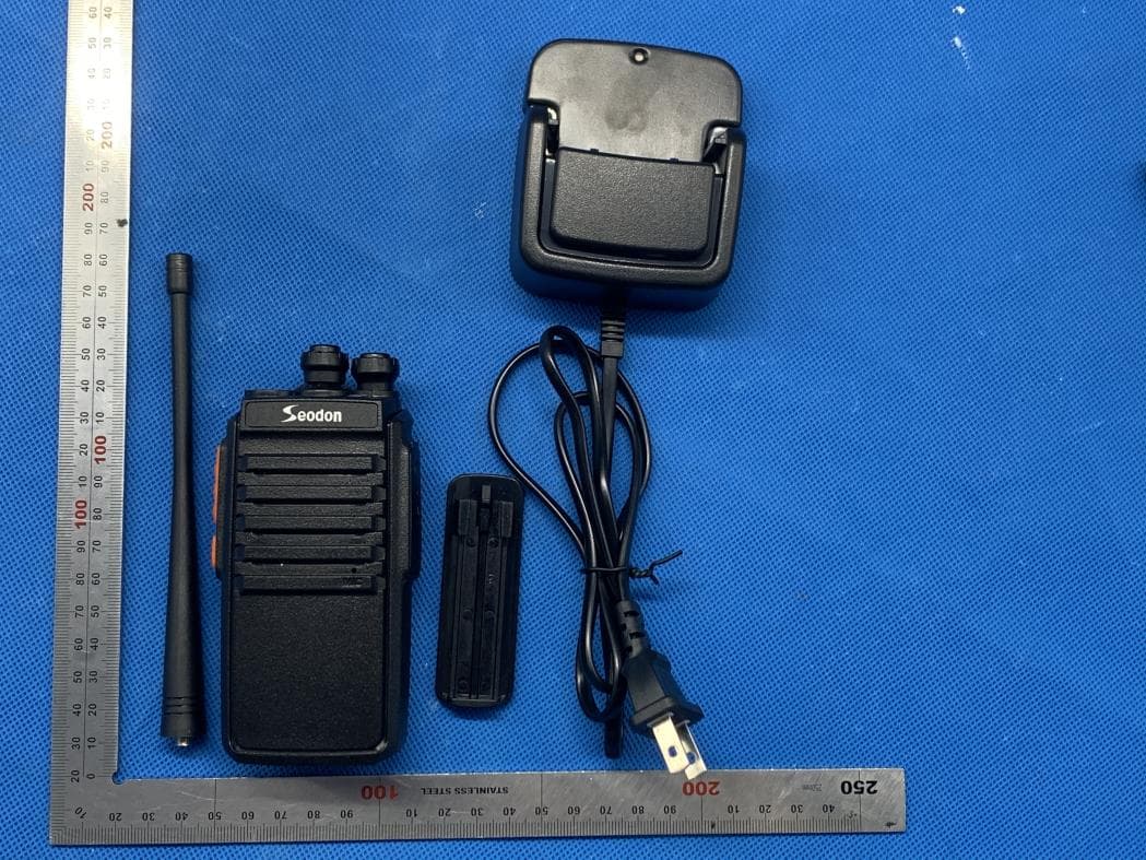
External Photos ALL VIEW OF SERIAES MODEL ALL VIEW OF SERIES MODEL-BACK VIEW SED-8S SED-6 ALL VIEW OF EUT TOP VIEW OF EUT Antenna BOTTOM VIEW OF EUT FRONT VIEW OF EUT BACK VIEW OF EUT LEFT VIEW OF EUT RIGHT VIEW OF EUT ALL VIEW OF EUT TOP VIEW OF EUT Antenna BOTTOM VIEW OF EUT FRONT VIEW OF EUT BACK VIEW OF EUT LEFT VIEW OF EUT RIGHT VIEW OF EUT
ID Label/Location Info
FCC ID Label Location FCC ID: 2AXYD-US068SFWD
Internal Photos
Internal Photos OPEN VIEW-1 OF EUT OPEN VIEW-1 OF EUT OPEN VIEW-2 OF EUT INTERNAL VIEW-1 OF EUT INTERNAL VIEW-2 OF EUT INTERNAL VIEW-2 OF EUT INTERNAL VIEW-3 OF EUT INTERNAL VIEW-4 OF EUT OPEN VIEW-1 OF EUT OPEN VIEW-1 OF EUT OPEN VIEW-2 OF EUT INTERNAL VIEW-1 OF EUT INTERNAL VIEW-2 OF EUT INTERNAL VIEW-3 OF EUT INTERNAL VIEW-4 OF EUT INTERNAL VIEW-5 OF EUT
RF Exposure Info
Page 1 of 20 CALIBRATION DATA PROBE CALIBRATION DATA Page 2 of 20 Page 3 of 20 Page 4 of 20 Page 5 of 20 Page 6 of 20 Page 7 of 20 Page 8 of 20 Page 9 of 20 Page 10 of 20 DAE CALIBRATION DATA Page 11 of 20 Page 12 of 20 Page 13 of 20 Page 14 of 20 Page 15 of 20 DIPOLE CALIBRATION DATA Page 16 of 20 Page 17 of 20 Page 18 of 20 Page 19 of 20 Page 20 of 20
RF Exposure Info
Page 1 of 39 SAR Test Report Report No.: AGC11438210101FH01 FCC ID : 2AXYD-US068SFWD PRODUCT DESIGNATION : Two-way radio BRAND NAME : Seodon, Firward MODEL NAME : SED-6, SED-8S APPLICANT : Shenzhen Firward Technology Co., Ltd DATE OF ISSUE : Mar. 23,2021 STANDARD(S) : IEEE Std. 1528:2013 FCC 47 CFR Part 2§2.1093:2013 IEEE Std C95.1 ™-2005 IEC 62209-1: 2016 REPORT VERSION : V1.0 Attestation of Global Compliance(Shenzhen) Co., Ltd. Report No.: AGC11438210101FH01 Page 2 of 39 Report Revise Record Report Version Revise Time Issued Date Valid Version Notes V1.0 / Mar. 23,2021 Valid Initial Release Report No.: AGC11438210101FH01 Page 3 of 39 Test Report Applicant Name Shenzhen Firward Technology Co., Ltd Applicant Address 501 Juji Science&Technology Building, Bianyabian Xueziwei Baoan Ave. Shajing, Shenzhen, Guangdong, China Manufacturer Name Shenzhen Firward Technology Co., Ltd Manufacturer Address 501 Juji Science&Technology Building, Bianyabian Xueziwei Baoan Ave. Shajing, Shenzhen, Guangdong, China Factory Name Shenzhen Firward Technology Co., Ltd Factory Address 501 Juji Science&Technology Building, Bianyabian Xueziwei Baoan Ave. Shajing, Shenzhen, Guangdong, China Product Designation Two-way radio Brand Name Seodon, Firward Model Name SED-6, SED-8S Different Description Only model, brand and shell design are different The brand of SED-6 is Firward and the brand of SED-8S is Seodon. EUT Voltage DC3.7 V Applicable Standard IEEE Std. 1528:2013 FCC 47 CFR Part 2§2.1093:2013 IEEE Std C95.1 ™-2005 IEC 62209-1: 2016 Test Date Mar. 23,2021 Report Template AGCRT- US -PTT/SAR (2018-02-02) Note: The results of testing in this report apply to the product/system which was tested only. Prepared By Thea Huang (Project Engineer) Mar. 23,2021 Reviewed By Angela Li (Reviewer) Mar. 23,2021 Approved By Forrest Lei (Authorized Officer) Mar. 23,2021 Report No.: AGC11438210101FH01 Page 4 of 39 TABLE OF CONTENTS 1. SUMMARY OF MAXIMUM SAR VALUE ....................................................................................................... 5 2. GENERAL INFORMATION ............................................................................................................................ 6 2.1. EUT DESCRIPTION ...................................................................................................................................... 6 3. SAR MEASUREMENT SYSTEM ..................................................................................................................... 7 3.1. THE DASY5 SYSTEM USED FOR PERFORMING COMPLIANCE TESTS CONSISTS OF FOLLOWING ITEMS.................... 7 3.2. DASY5 E-FIELD PROBE .............................................................................................................................. 8 3.3. DATA ACQUISITION ELECTRONICS DESCRIPTION ............................................................................................. 8 3.4. ROBOT ....................................................................................................................................................... 9 3.5. LIGHT BEAM UNIT ....................................................................................................................................... 9 3.6. DEVICE HOLDER ....................................................................................................................................... 10 3.7. MEASUREMENT SERVER ............................................................................................................................ 10 3.8. PHANTOM ............................................................................................................................................... 11 4. SAR MEASUREMENT PROCEDURE .......................................................................................................... 12 4.1. SPECIFIC ABSORPTION RATE (SAR) ........................................................................................................... 12 4.2. SAR MEASUREMENT PROCEDURE ............................................................................................................. 13 5. TISSUE SIMULATING LIQUID ..................................................................................................................... 15 5.1. THE COMPOSITION OF THE TISSUE SIMULATING LIQUID ................................................................................... 15 5.2. TISSUE DIELECTRIC PARAMETERS FOR HEAD AND BODY PHANTOMS .............................................................. 15 5.3. TISSUE CALIBRATION RESULT ..................................................................................................................... 16 6. SAR SYSTEM CHECK PROCEDURE ......................................................................................................... 17 6.1. SAR SYSTEM CHECK PROCEDURES ........................................................................................................... 17 7. EUT TEST POSITION ................................................................................................................................... 19 7.1. BODY WORN POSITION .............................................................................................................................. 19 8. SAR EXPOSURE LIMITS ............................................................................................................................ 20 9. TEST FACILITY ........................................................................................................................................... 21 10. TEST EQUIPMENT LIST ........................................................................................................................... 22 11. MEASUREMENT UNCERTAINTY .............................................................................................................. 23 12. POWER MEASUREMENT ......................................................................…
Text truncated - open the document above for the full version.
Test Report
Page 1 of 58 Report No.: AGC11438210101FE10 FCC ID : 2AXYD-US068SFWD PRODUCT DESIGNATION : Two-way radio BRAND NAME : Seodon, Firward MODEL NAME : SED-6, SED-8S APPLICANT : Shenzhen Firward Technology Co.,Ltd DATE OF ISSUE : Mar. 22, 2021 STANDARD(S) : FCC Part 90 Rules REPORT VERSION : V 1.0 Attestation of Global Compliance (Shenzhen) Co., Ltd FCC Test Report Report No.:AGC11438210101FE10 Page 2 of 58 Report Revise Record Report Version Revise Time Issued Date Valid Version Notes V1.0 / Mar. 22, 2021 Valid Initial Release Report No.:AGC11438210101FE10 Page 3 of 58 TABLE OF CONTENTS 1. VERIFICATION OF COMPLIANCE ....................................................................................... 5 2. GENERAL INFORMATION .................................................................................................... 6 2.1PRODUCT DESCRIPTION ........................................................................................................................ 6 2.2RELATED SUBMITTAL(S) / GRANT (S) .................................................................................................... 9 2.3 TEST METHODOLOGY ........................................................................................................................... 9 2.4 ADDRESS OF THE TEST LABORATORY ............................................................................................... 9 2.5 TEST FACILITY ........................................................................................................................................ 9 2.6 SPECIAL ACCESSORIES ...................................................................................................................... 10 2.7 EQUIPMENT MODIFICATIONS ............................................................................................................. 10 3. SYSTEM TEST CONFIGURATION ...................................................................................... 11 3.1EUT CONFIGURATION ............................................................................................................................ 11 3.2 EUT EXERCISE ...................................................................................................................................... 11 3.3 MEASUREMENT UNCERTAINTY ........................................................................................................... 11 3.4 CONFIGURATION OF TESTED SYSTEM ............................................................................................. 12 4. SUMMARY OF TEST RESULTS ......................................................................................... 13 5. DESCRIPTION OF TEST MODES ...................................................................................... 15 6. FREQUENCY TOLERANCE ............................................................................................... 16 6.1 PROVISIONS APPLICABLE ................................................................................................................... 16 6.2 MEASUREMENT PROCEDURE ............................................................................................................ 16 6.3 TEST SETUP BLOCK DIAGRAM ........................................................................................................... 17 6.4 TEST RESULTS ..................................................................................................................................... 18 7. EMISSION BANDWIDTH ....................................................................................................... 19 7.1 PROVISIONS APPLICABLE ................................................................................................................... 19 7.2 MEASUREMENT PROCEDURE ............................................................................................................ 19 7.3 TEST SETUP BLOCK DIAGRAM ........................................................................................................... 19 7.4 MEASUREMENT RESULT ..................................................................................................................... 21 8.UNWANTED RADIATION .................................................................................................... 24 8.1 PROVISIONS APPLICABLE ................................................................................................................... 24 8.2 MEASUREMENT PROCEDURE ............................................................................................................ 24 8.3 TEST SETUP BLOCK DIAGRAM ........................................................................................................... 25 8.4 MEASUREMENT RESULTS: .................................................................................................................. 26 8.5 EMISSION MASK PLOT ......................................................................................................................... 35 9.MODULATION CHARACTERISTICS ..................................................................................... 38 9.1 PROVISIONS APPLICABLE ................................................................................................................... 38 Report No.:AGC11438210101FE10 Page 4 of 58 9.2 MEASUREMENT METHOD ................................................................................................................... 38 9.3 MEASUREMENT RESULT ..................................................................................................................... 39 10.MAXIMUMN TRANSMITTER POWER (CONDUCTED OUTPUT POWER) PEAK POWER 42 10.1 PROVISIONS APPLICABLE ................................................................................................................. 42 10.2 TEST PROCEDURE ............................................................................................................................. 42 10.3 TEST CONFIGURATION ..........…
Text truncated - open the document above for the full version.
Test Setup Photos
Test Setup Photos RADIATED EMISSION BELOW 1G TEST SETUP RADIATED EMISSION ABOVE 1G TEST SETUP CONDUCTED TEST SETUP
Test Setup Photos
Test Setup Photos Face Up with 2.5 cm Separation Distance. Body Back Touch with all accessories The thickness of EUT is 3.0 cm 25mm
Contact Information
Applicant
Alisa Li(Boss)
Test Firm
Attestation of Global Compliance (Shenzhen) Co., LDoris Li
[email protected]+86-755-25234088
Technical Specifications
| # | Rule Parts | Frequency Range | Power Output | Emission | Tolerance |
|---|---|---|---|---|---|
| 1 | 90 | 450 MHz - 470 MHz | 2 W | 11K0F3E | 2.5000000000 ppm |
Other Applications from Shenzhen Firward Technology Co.,Ltd
2AXYDSED-8
Nov 30, 2020Two-way radio
Equipment Class
CSR - Scanning Receiver