2AXYM-N2OTAA01Noah Multifunction Leak Sensor
Kairos Water, Inc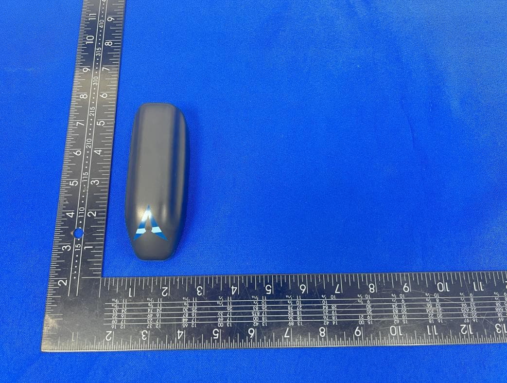
Click to zoom
Application Details
- Equipment Class
- DSS - Part 15 Spread Spectrum Transmitter
- Date of Grant
- Dec 08, 2024
- Application Purpose
- Original Equipment
- Date of Application
- Dec 08, 2024
- Equipment Note
- Noah Multifunction Leak Sensor
- Frequency Range
- 902.30000000 - 914.90000000
- Company
- Kairos Water, Inc
- Country
- United States
Documents & Files
Document Text
Text extracted from the exhibit documents filed with the FCC. Open a document above to read the original.
Users Manual
Noah Quick Set-up Guide Before Starting Be sure that you have set-up your KAIROS account at app.kairoswater.io and that you have a K1 Gateway set-up to receive data from Noah devices. Preparing the Hardware Each Noah Multifunction Leak Sensor is comprised of: • One (1) Noah Multifunction Leak Sensor Module • One (1) Connecting Cable • One (1) Noah membrane (available in a variety of formats) • Two (2) cable retaining clips • Two (2) squares of mounting tape • One (1) small piece of gaffer's tape Set-up the Noah Wireless Module 1. Ensure the device is added to your account 2. Press the button on the bottom of the module while checking the LED in the nose for a flash of green. 3. If the LED does not flash green, the module is off. Push and hold the button for three (3) seconds until the LED begins to flash red-green-blue. 4. Check app.kairoswater.io to see if the module is showing as online now. (NOTE: you must be within range of a K1 gateway.) 5. More detailed information, including troubleshooting steps, is available in the Noah User Manual. Preparing for Installation For the best sensitivity, the membranes should be installed over a flat surface, free of debris, deep gaps, or dirt/sand/dust. It is a good practice to sweep or vacuum the space onto which the membrane will be applied. In addition, for the “Tee” sensors and some water heater installations, it will be important to ensure the surfaces on which adhesive will be applied are cleaned before adhering the membrane to the surface. Installing Membranes 1. 1. Ensure that the membrane you are preparing to install is appropriately sized for the area it will be monitoring. There are a variety of membrane formats available for installation. Choosing the correct one for the area you want to monitor is important. More on membrane selection in the Installing Membranes section. 2. Membranes should cover the maximum area under the monitored space without bending or buckling. Ideally, the membrane should not stick out in highly trafficked areas where they would be stepped on or kicked out of position. 3. Some membranes come with extra tabs, if the cable is attached to one tab, and the other becomes unnecessary or interferes with the installation, you may cut it off so that the edge if flush with the bulk of the membrane. 4. There is a protective film covering the black conductive traces. THIS PLASTIC FILM MUST BE REMOVED BEFORE INSTALLATION. Simply peel it away from the heavier plastic and traces. 5. Connect the membranes to the wireless modules using the supplied cable. 6. If the cable is not already attached to the membrane, 1. Slide one of the tabs sticking out from the membrane into the slot of the ribbon connector making sure the dull black strips are touching the silver contacts in the white connector. 2. Clamp the cover over the tab so that the dull black contacts on the membrane touch the contacts inside the ribbon connector. 3. Insert the small plug into one of the wireless module's ports. 6. In the spaces where the membranes will be slid under the thin gap for an appliance (dishwasher, refrigerator, washing machine, etc), the wireless module can be tucked under the cabinet overhang using the 3M adhesive on its bottom. Cords can be tucked underneath and retained using the provided wire clips, or in a space under or next to the appliance. Additionally, the small strip of gaffer's tape can be used to hold the membrane connector to the floor. TIP: Place the module in either a vertically or horizontally level orientations as shown in the following illustrations to ensure the tamper sensor is not triggered by ambient vibrations. 9”x18” Format This format is recommended for Ice Machines and smaller coverage areas where the larger format will not fit. This format can be shortened by cutting it along the horizontal between the black traces an through a row of perforations leaving a connection tab for both halves – depicted below. The remaining halves can be connected to separate wireless modules or two ports on one wireless module. 20”20” Format This format is recommended for Clothes and Dish Washing Machines. As with the 9”x18” membrane, this format can be shortened by cutting it along the horizontal between the black traces an through a row of perforations leaving a connection tab for both halves – depicted below. The remaining halves can be connected to separate wireless modules or two ports on one wireless module. 20”x30” Format This format is recommended for refrigerators and the largest areas. Once again, this format can be shortened by cutting it along the horizontal between the black traces an through a row of perforations leaving a connection tab for both halves – depicted below. The remaining halves can be connected to separate wireless modules or two ports on one wireless module. Water Heater & PTAC (6”x30”) Format This format is designed to fit under most PTAC (Portable Terminal Air Conditioning) units and wrap around water heaters when cut in half. After cutting “bridges” 1 and 2, regions “A” and “B” can be monitored separately by connecting the leads from “a” and “b” connection bridges into separate wireless modules. In this way, the amount of fluid covering the membrane can be determined by the number of regions that are alarming. The design can be cut in half to create two 3”x30” membranes to wrap around opposing sides of a water heater . Each half should be connected to a wireless module. Small adhesive tabs should be placed at the top corners of the membrane to keep the plastic attached to the side of the water heater. The connection tab and the plastic edge should touch the floor around the water heater. 1”x12” (Tee) Format This format is recommended for tight spaces and around the base of toilets or inside overflow/condensation pans. “Tee” design of the Noah Membrane primarily for monitoring toilet bowl overflow and leaks where a wide, flat sheet is inconvenient Tee membrane installed on the back of a toilet base where anod…
Text truncated - open the document above for the full version.
Attestation Statements
{Kairos Water, Inc} { 1700 Northside Drive Suite A7, Unit #5543, Atlanta, GA 30318 United States } The information provided in this letter is based on the referenced rule parts of Title 47 of the CFR as well as KDB 986446 D01. Federal Communications Commission Authorization and Evaluation Division Equipment Authorization Branch 7435 Oakland Mills Road Columbia, MD 21046 {2024.11.19} To whom it may concern: We, {Kairos Water, Inc}, hereby certify that the equipment for which authorization is sought (FCC ID: {2AXYM}{-N2OTAA01}) is not “covered” equipment prohibited from receiving an equipment authorization pursuant to § 2.903 of the FCC rules. We also certify that, as of the date of the filing of the application, we are not identified on the Covered List (https://www.fcc.gov/supplychain/coveredlist) as an entity producing “covered” equipment. By signing this form, we confirm the above and that we are aware of the application requirements listed under § 2.911(b) and (d)(5) and (6). Sincerely, Signature { Seth Lawrence } { Taylor } { Engineer} {Kairos Water, Inc} 62_[model] CoveredEqu_2.911(d)(5)(i) and (ii) - U, V02
Attestation Statements
{Kairos Water, Inc} {1700 Northside Drive Suite A7, Unit #5543, Atlanta, GA 30318 United States } Federal Communications Commission Authorization and Evaluation Division Equipment Authorization Branch 7435 Oakland Mills Road Columbia, MD 21046 11/19/2024 U.S. Agent Designation [Kairos Water, Inc] acknowledges their consent for the following contact located in the United States to act as their agent for service of process for the equipment for which authorization is sought (FCC ID:2AXYM- N2OTAA01): Name and company of U.S. agent: Kairos IoT water controls llc Physical U.S. address of agent: 1700 Northside Drive Suite A7, Unit #5543, Atlanta, GA 30318 United States FRN of U.S. agent: 0030335772 Email address of U.S. agent: [email protected] [Kairos Water, Inc] acknowledges their obligation to accept service of process on behalf of [Kairos Water, Inc]. [Kairos Water, Inc] with the FRN [0030335772] accepts its obligation to maintain an agent for service of process in the United States for no less than one year after either the grantee has permanently terminated all marketing and importation of the applicable equipment within the U.S., or the conclusion of any Commission-related administrative or judicial proceeding involving the equipment, whichever is later. By signing this form, we confirm the above and that we are aware of the application requirements listed under § 2.911(d)(7). The information provided in this letter is based on the referenced rule parts of Title 47 of the CFR as well as KDB 986446 D01. An expiration date for this letter does not exist. In case the U.S. agent changes, the grantee is obligated to notify the FCC within 30 days via the granting TCB. Sincerely, Signature Seth Lawrence Taylor Engineer Kairos Water, Inc Signature Seth Lawrence Taylor Engineer Kairos Water, Inc 48_[mo del] US_Agent_2.911(d)(7) - U, V05
Cover Letter(s)
CONFIDENTIALITY REQUEST for Certification Service in USA Federal Communication Commission Equipment Authorization Division, Application Processing Branch 7435 Oakland Mills Road Columbia, MD 21046 Date:<{2024.11.19}> Pursuant to Paragraphs §0.457 and 0.459 of the Commission’s Rules (47 C.F.R.) and Section §552(b)(4) of the Freedom of Information Act, we requests confidentiality for the following products: FCC ID Model name {2AXYM }{-N2OTAA01} { Noah Multifunction Leak Sensor } For the product stated above, we request that the following information be held confidential; Exhibits Long-Term Confidentiality Short-Term Confidentiality Short-Term Confidentiality Days External Photos Internal Photos Block Diagram Schematics Test Setup Photos User’s Manual Parts List Tune Up Operational Descriptions The long-term confidentiality exhibits contain our trade secrets and proprietary information that could be of benefit to our competitors. The short-term confidentiality on the basis of ensuring that business sensitive information remains confidential until the actual marketing of our new device. If you have any questions, please feel free to contact me at the address shown below. Sincerely, Name/Title: { Seth Lawrence } { Taylor} /{ Engineer } Company: {Kairos Water, Inc} Address: {1700 Northside Drive Suite A7, Unit #5543, Atlanta, GA 30318 United States} Phone: {7576941179} Fax: {/} E-Mail: { [email protected] }
Cover Letter(s)
Kairos Water, Inc 1700 Northside Drive Suite A7, Unit #5543, Atlanta, GA 30318 United States Federal Communications Commission Authorization and Evaluation Division Equipment Authorization Branch 7435 Oakland Mills Road Columbia, MD 21046 {2024.11.19} To whom it may concern: We, the undersigned, hereby authorize Eurofins Product Service GmbH to act on our behalf in all matters relating to applications for equipment authorization FCC ID: {2AXYM}{-N2OTAA01} including the signing of all documents related to these matters. Any and all acts carried out by Eurofins Product Service GmbH on our behalf shall have the same effect as acts of our own. By signing this application form, we agree to Eurofins’ current valid General Terms and Conditions (AGB),Testing and Certification Regulations (PZO) which can be viewed on following website www.eurofins.de/ee or retrieved on request. We also hereby certify that no party to this application is subject to a denial of benefits, including FCC benefits, pursuant to Section 5301 of the Anti-Drug Abuse Act of 1988, 21 U.S.C. 862. Sincerely, Name/Title: { Seth Lawrence } { Taylor} /{ Engineer } Company: {Kairos Water, Inc} Address: { 1700 Northside Drive Suite A7, Unit #5543, Atlanta, GA 30318 United States } Phone: {7576941179} Fax: {/} E-Mail: { [email protected] }
External Photos
FCC ID: 2AXYM-N2OTAA01 Page 1 of 3 Report No.: CTL2407153031-WF External Photos of EUT FCC ID: 2AXYM-N2OTAA01 Page 2 of 3 Report No.: CTL2407153031-WF FCC ID: 2AXYM-N2OTAA01 Page 3 of 3 Report No.: CTL2407153031-WF
ID Label/Location Info
FCC ID: 2AXYM-N2OTAA01 Page 1 of 1 Report No.: CTL2407153031-WF FCC ID Label Information Label location: Size: L1.0cm*W0.5cm Noah Multifunction Leak Sensor Model: N2-OTAA-01 FCC ID: 2AXYM-N2OTAA01
ID Label/Location Info
FCC ID: 2AXYM-N2OTAA01 Page 1 of 1 Report No.: CTL2407153031-WF FCC ID Label Information Label location: Size: L1.0cm*W0.5cm Noah Multifunction Leak Sensor Model: N2-OTAA-01 FCC ID: 2AXYM-N2OTAA01
Internal Photos
FCC ID: 2AXYM-N2OTAA01 Page 1 of 3 Report No.: CTL2407153031-WF Internal Photos of EUT Antenna FCC ID: 2AXYM-N2OTAA01 Page 2 of 3 Report No.: CTL2407153031-WF FCC ID: 2AXYM-N2OTAA01 Page 3 of 3 Report No.: CTL2407153031-WF
RF Exposure Info
FCC ID: 2AXYM-N2OTAA01 Page 1 of 2 Report No.: CTL2407153031-WF RF Exposure evaluation FCC ID: 2AXYM-N2OTAA01 Exposure category: General population/uncontrolled environment EUT Type: Production Unit Device Type: Mobile Device 1. Reference According to §1.1307(b)(1), systems operating under the provisions of this section shall be operated in a manner that ensures that the public is not exposed to radio frequency energy level in excess of the Commission’s guidelines. According to §1.1310 and §2.1091 RF exposure is calculated. KDB447498 D01: Mobile and Portable Devices RF Exposure Procedures and Equipment Authorization Policies 2. Limit Limits for Maximum Permissible Exposure (MPE)/Controlled Exposure Frequency Range(MHz) Electric Field Strength(V/m) Magnetic Field Strength(A/m) Power Density (mW/cm²) Averaging Time (minute) Limits for Occupational/Controlled Exposure 0.3 – 3.0 3.0 – 30 30 – 300 300 – 1500 1500 – 100,000 614 1842/f 61.4 / / 1.63 4.89/f 0.163 / / (100) * (900/f 2 )* 1.0 f/300 5 6 6 6 6 6 Limits for Maximum Permissible Exposure (MPE)/Uncontrolled Exposure Frequency Range(MHz) Electric Field Strength(V/m) Magnetic Field Strength(A/m) Power Density (mW/cm²) Averaging Time (minute) Limits for Occupational/Controlled Exposure 0.3 – 3.0 3.0 – 30 30 – 300 300 – 1500 1500 – 100,000 614 824/f 27.5 / / 1.63 2.19/f 0.073 / / (100) * (180/f 2 )* 0.2 f/1500 1.0 30 30 30 30 30 F=frequency in MHz *=Plane-wave equivalent power density FCC ID: 2AXYM-N2OTAA01 Page 2 of 2 Report No.: CTL2407153031-WF 3. MPE Calculation Method Predication of MPE limit at a given distance Equation from page 18 of OET Bulletin 65, Edition 97-01 S=PG/4πR² Where: S=power density P=power input to antenna G=power gain of the antenna in the direction of interest relative to an isotropic radiator R=distance to the center of radiation of the antenna 4. Antenna Information The device can use antennas certificated as follows provided by manufacturer; Type Antenna type Frequency Range Antenna Gain SRD PCB Antenna 902.3-914.9MHz 2.33dBi 5. Conducted power and Manufacturing Tolerance RFID Channel Channel 00 Channel 32 Channel 63 Target (dBm) 13.0 13.0 13.0 Tolerance ±(dB) 1.0 1.0 1.0 6. Standalone MPE Result As declared by the Applicant, the EUT is a wireless device used in a fix application, at least 20 cm from any body part of the user or nearby persons; from the maximum EUT RF output power, the minimum separation distance, r =20cm, as well as the max. gain of the used antenna, the RF power density can be obtained. Modulation Type Max tune up power tolerance(dBm) Max Output power to antenna (mW) Antenna Gain (Numeric) Power Density at R=20cm (mW/cm2) Limit (mW/cm2) Result ASK 14 25.1189 1.7100 0.0085 0.6185 Pass 7. Conclusion The measurement results comply with the FCC Limit per 47 CFR 2.1091 for the uncontrolled RF Exposure of mobile device. ----------------THE END OF REPORT---------------
Test Report
868/915MHz Antenna Proposal Report Project:868/915MHz Antenna Proposal Report 868 - 915MHz Report Date: 2024.11.28 Report Version: 1.0 Prepared by: KEN Approved by: IAN Manufacturer: Shenzhen Fusheng Cloud Technology Co., LTD Address: Room A1302, Gaosheng Building, No. 18, Shajing Street Center Road, Bao'an District, ShenZhen,China Contents: 1. Testing Item & Equipment 2.Test Results 3.1 S-Parameters 3.2 Efficiency and Peak Gain 1. Testing Item & Equipment 868/915MHz天线 3. 2 Efficiency and Peak Gain 868MHz 915MHz 890MHz
Test Report
Shenzhen CTL Testing Technology Co., Ltd. Tel: +86-755-89486194 E-mail: [email protected] TEST REPORT FCC PART 15.247 Report Reference No.................: CTL2407153031-WF Compiled by: ( position+printed name+signature) Happy Guo (File administrators) Tested by: ( position+printed name+signature) JamesYu (Test Engineer) Approved by: ( position+printed name+signature) Ivan Xie (Manager) Product Name ............................ : Noah Multifunction Leak Sensor Model/Type reference ................ : N2-OTAA-01 List Model(s) ............................... : N/A Trade Mark .................................. : KAIROS FCC ID ......................................... : 2AXYM-N2OTAA01 Applicant’s name ....................... : Kairos Water, Inc Address of applicant ................. : 1700 Northside Drive Suite A7, Unit #5543, Atlanta, GA 30318 United States Test Firm ..................................... : Shenzhen CTL Testing Technology Co., Ltd. Address of Test Firm ................. : Floor 1-A, Baisha Technology Park, No.3011, Shahexi Road, Nanshan District, Shenzhen, China 518055 Test specification ....................... : Standard ...................................... : FCC Part 15.247: Operation within the bands 902-928 MHz, 2400-2483.5 MHz and 5725-5850 MHz. TRF Originator ............................. : Shenzhen CTL Testing Technology Co., Ltd. Master TRF .................................. : Dated 2011-01 Date of receipt of test item ........ : Oct. 10, 2024 Date of Test Date ........................ : Oct. 10, 2024-Oct. 29, 2024 Date of Issue .............................. : Oct. 30, 2024 Result .......................................... : Pass Shenzhen CTL Testing Technology Co., Ltd. All rights reserved. This publication may be reproduced in whole or in part for non-commercial purposes as long as the Shenzhen CTL Testing Technology Co., Ltd. is acknowledged as copyright owner and source of the material. Shenzhen CTL Testing Technology Co., Ltd. takes no responsibility for and will not assume liability for damages resulting from the reader's interpretation of the reproduced material due to its placement and context. V1.0 Page 2 of 35 Report No.: CTL2407153031-WF TEST REPORT Test Report No. : CTL2407153031-WF Oct. 30, 2024 Date of issue Equipment under Test : Noah Multifunction Leak Sensor Sample No : CTL2407153031 Model /Type : N2-OTAA-01 Listed Models : N/A Applicant : Kairos Water, Inc Address : 1700 Northside Drive Suite A7, Unit #5543, Atlanta, GA 30318 United States Manufacturer : Kairos Water, Inc Address : 1700 Northside Drive Suite A7, Unit #5543, Atlanta, GA 30318 United States Test result Pass * *In the configuration tested, the EUT complied with the standards specified page 5. The test results presented in this report relate only to the object tested. This report shall not be reproduced, except in full, without the written approval of the issuing testing laboratory. V1.0 Page 3 of 35 Report No.: CTL2407153031-WF ** Modified History ** Revisions Description Issued Data Report No. Remark Version 1.0 Initial Test Report Release 2024-10-30 CTL2407153031-WF Tracy Qi V1.0 Page 4 of 35 Report No.: CTL2407153031-WF Table of Contents Page 1. SUMMARY ............................................................................................................................................................... 5 1.1. TEST STANDARDS ..................................................................................................................................................... 5 1.2. TEST DESCRIPTION ........................................................................................................................................................ 5 1.3. TEST FACILITY .............................................................................................................................................................. 6 1.4. STATEMENT OF THE MEASUREMENT UNCERTAINTY ............................................................................................................... 6 2. GENERAL INFORMATION .......................................................................................................................................... 8 2.1. ENVIRONMENTAL CONDITIONS ........................................................................................................................................ 8 2.2. GENERAL DESCRIPTION OF EUT ...................................................................................................................................... 8 2.3. DESCRIPTION OF TEST MODES AND TEST FREQUENCY .......................................................................................................... 9 2.4. EQUIPMENTS USED DURING THE TEST ............................................................................................................................ 10 2.5. RELATED SUBMITTAL(S) / GRANT (S) .............................................................................................................................. 10 2.6. MODIFICATIONS ......................................................................................................................................................... 10 3. TEST CONDITIONS AND RESULTS ............................................................................................................................ 11 3.1. CONDUCTED EMISSIONS TEST ....................................................................................................................................... 11 3.2. RADIATED EMISSIONS AND BAND EDGE .......................................................................................................................... 12 3.3. MAXIMUM PEAK OUTPUT POWER ................................................................................................................................ 22 3.4. 20DB BANDWIDTH .......................................................................................…
Text truncated - open the document above for the full version.
Test Report
FCC ID: 2AXYM-N2OTAA01 Page 1 of 21 Report No.: CTL2407153031-WF Page 1 / 21 1. Bandwidth 1.1 Test Result 1.1.1 OBW Mode TX Type Frequency (MHz) ANT 99% Occupied Bandwidth (MHz) Verdict Result Limit LoRa SISO 902.3 1 0.130 / Pass 908.7 1 0.129 / Pass 914.9 1 0.130 / Pass 1.1.2 20dB BW Mode TX Type Frequency (MHz) ANT 20dB Bandwidth (MHz) Verdict Result Limit LoRa SISO 902.3 1 0.138 <=0.25 Pass 908.7 1 0.144 <=0.25 Pass 914.9 1 0.139 <=0.25 Pass FCC ID: 2AXYM-N2OTAA01 Page 2 of 21 Report No.: CTL2407153031-WF Page 2 / 21 1.2 Test Graph 1.2.1 OBW LoRa_LCH_902.3MHz_Ant1_NTNV LoRa_MCH_908.7MHz_Ant1_NTNV FCC ID: 2AXYM-N2OTAA01 Page 3 of 21 Report No.: CTL2407153031-WF Page 3 / 21 LoRa_HCH_914.9MHz_Ant1_NTNV FCC ID: 2AXYM-N2OTAA01 Page 4 of 21 Report No.: CTL2407153031-WF Page 4 / 21 1.2.2 20dB BW LoRa_LCH_902.3MHz_Ant1_NTNV LoRa_MCH_908.7MHz_Ant1_NTNV FCC ID: 2AXYM-N2OTAA01 Page 5 of 21 Report No.: CTL2407153031-WF Page 5 / 21 LoRa_HCH_914.9MHz_Ant1_NTNV FCC ID: 2AXYM-N2OTAA01 Page 6 of 21 Report No.: CTL2407153031-WF Page 6 / 21 2. Maximum Conducted Output Power 2.1 Test Result 2.1.1 Power Mode TX Type Frequency (MHz) Maximum Peak Conducted Output Power (dBm) Verdict ANT1 Limit LoRa SISO 902.3 13.28 <=30 Pass 908.7 13.23 <=30 Pass 914.9 13.17 <=30 Pass Note1: Antenna Gain: Ant1: 2.47dBi; FCC ID: 2AXYM-N2OTAA01 Page 7 of 21 Report No.: CTL2407153031-WF Page 7 / 21 2.2 Test Graph 2.2.1 Power LoRa_LCH_902.3MHz_Ant1_NTNV LoRa_MCH_908.7MHz_Ant1_NTNV FCC ID: 2AXYM-N2OTAA01 Page 8 of 21 Report No.: CTL2407153031-WF Page 8 / 21 LoRa_HCH_914.9MHz_Ant1_NTNV FCC ID: 2AXYM-N2OTAA01 Page 9 of 21 Report No.: CTL2407153031-WF Page 9 / 21 3. Carrier Frequency Separation 3.1 Test Result 3.1.1 Ant1 Ant1 Mode TX Type Frequency (MHz) Channel Separation (MHz) 20dB Bandwidth (MHz) Limit (MHz) Verdict LoRa SISO HOPP 0.200 0.144 >=0.144 Pass FCC ID: 2AXYM-N2OTAA01 Page 10 of 21 Report No.: CTL2407153031-WF Page 10 / 21 3.2 Test Graph 3.2.1 Ant1 LoRa_HOPP_Ant1_NTNV FCC ID: 2AXYM-N2OTAA01 Page 11 of 21 Report No.: CTL2407153031-WF Page 11 / 21 4. Number of Hopping Frequencies 4.1 Test Result 4.1.1 HoppNum Mode TX Type Frequency (MHz) Num of Hopping Frequencies Verdict ANT1 Limit LoRa SISO HOPP 64 >=50 Pass FCC ID: 2AXYM-N2OTAA01 Page 12 of 21 Report No.: CTL2407153031-WF Page 12 / 21 4.2 Test Graph 4.2.1 HoppNum LoRa_HOPP_Ant1_NTNV FCC ID: 2AXYM-N2OTAA01 Page 13 of 21 Report No.: CTL2407153031-WF Page 13 / 21 5. Time of Occupancy (Dwell Time) 5.1 Test Result 5.1.1 Ant1 Ant1 Mode TX Type Frequency (MHz) Duration of Single Pulse (ms) Observation Period (s) Num of Pulse in Observation Period Dwell Time (ms) Limit (ms) Verdict LoRa SISO HOPP 279.106 20.000 1 279.106 <=400 PASS FCC ID: 2AXYM-N2OTAA01 Page 14 of 21 Report No.: CTL2407153031-WF Page 14 / 21 5.2 Test Graph 5.2.1 Ant1 LoRa_HOPP_Ant1_NTNV LoRa_HOPP_Ant1_NTNV FCC ID: 2AXYM-N2OTAA01 Page 15 of 21 Report No.: CTL2407153031-WF Page 15 / 21 6. Unwanted Emissions In Non-restricted Frequency Bands 6.1 Test Result 6.1.1 Ref Mode TX Type Frequency (MHz) ANT Level of Reference (dBm) LoRa SISO 902.3 1 13.21 908.7 1 13.18 914.9 1 13.09 Note1: Refer to FCC Part 15.247 (d) and ANSI C63.10-2013, the channel contains the maximum PSD level was used to establish the reference level. 6.1.2 CSE Mode TX Type Frequency (MHz) ANT Level of Reference (dBm) Limit (dBm) Verdict LoRa SISO 902.3 1 13.21 -6.79 Pass 908.7 1 13.21 -6.79 Pass 914.9 1 13.21 -6.79 Pass HOPP 1 13.21 -6.79 Pass 13.21 -6.79 Pass Note1: Refer to FCC Part 15.247 (d) and ANSI C63.10-2013, the channel contains the maximum PSD level was used to establish the reference level. FCC ID: 2AXYM-N2OTAA01 Page 16 of 21 Report No.: CTL2407153031-WF Page 16 / 21 6.2 Test Graph 6.2.1 Ref LoRa_LCH_902.3MHz_Ant1_NTNV LoRa_MCH_908.7MHz_Ant1_NTNV FCC ID: 2AXYM-N2OTAA01 Page 17 of 21 Report No.: CTL2407153031-WF Page 17 / 21 LoRa_HCH_914.9MHz_Ant1_NTNV FCC ID: 2AXYM-N2OTAA01 Page 18 of 21 Report No.: CTL2407153031-WF Page 18 / 21 6.2.2 CSE LoRa_LCH_902.3MHz_Ant1_NTNV LoRa_LCH_902.3MHz_Ant1_NTNV FCC ID: 2AXYM-N2OTAA01 Page 19 of 21 Report No.: CTL2407153031-WF Page 19 / 21 LoRa_MCH_908.7MHz_Ant1_NTNV LoRa_HCH_914.9MHz_Ant1_NTNV FCC ID: 2AXYM-N2OTAA01 Page 20 of 21 Report No.: CTL2407153031-WF Page 20 / 21 LoRa_HCH_914.9MHz_Ant1_NTNV LoRa_HOPP_Ant1_NTNV FCC ID: 2AXYM-N2OTAA01 Page 21 of 21 Report No.: CTL2407153031-WF Page 21 / 21 LoRa_HOPP_Ant1_NTNV
Test Setup Photos
FCC ID: 2AXYM-N2OTAA01 Page 1 of 1 Report No.: CTL2407153031-WF Test Setup Photos of the EUT
Contact Information
Applicant
Seth Lawrence Taylor
Technical Contact
Kairos Water, IncSeth Lawrence Taylor
[email protected]7576941179
1700 Northside Drive Suite A7, Unit #5543, Atlanta · Atlanta, Georgia · United States
Non-Technical Contact
Kairos Water, IncSeth Lawrence Taylor
[email protected]7576941179
Test Firm
Shenzhen CTL Testing Technology Co., Ltd.Tracy Qi
[email protected]86-755-89486194
Technical Specifications
| # | Rule Parts | Frequency Range | Power Output |
|---|---|---|---|
| 1 | 15C | 902.3 MHz - 914.9 MHz | 21.30 mW |
Other Applications from Kairos Water, Inc

2AXYM-N3
Jul 22, 2026Noah Multifunction Leak Sensor
Equipment Class
DSS - Part 15 Spread Spectrum Transmitter
2AXYM-K0NAL
Jan 05, 2021Noah Multifunction Leak Sensor
Equipment Class
DSS - Part 15 Spread Spectrum Transmitter