2AXYZ-BT21-RWC15W Auto Wireless Charger
ROYCHE Co.,Ltd
Click to zoom
Application Details
- Equipment Class
- DCD - Part 15 Low Power Transmitter Below 1705 kHz
- Date of Grant
- Jan 06, 2021
- Application Purpose
- Original Equipment
- Date of Application
- Jan 06, 2021
- Equipment Note
- 15W Auto Wireless Charger
- Frequency Range
- 0.11000000 - 0.20500000
- Company
- ROYCHE Co.,Ltd
- Country
- South Korea
Documents & Files
Document Text
Text extracted from the exhibit documents filed with the FCC. Open a document above to read the original.
Users Manual
Caution: Changes or modifications not expressly approved by the party responsible for compliance could void the user's authority to operate the equipment.
Cover Letter(s)
ROYCHE Co.,Ltd 3 floor, 5, Bongeunsa-ro, 37-gil, Gangnam-gu, Seoul, Korea TEL: +82-2-701-2181, FAX: +82-2-701-2180 http://www.royche.co.kr December 11, 2020 Federal Communications Commission Equipment Authorization Division, Application Processing Branch 7435 Oakland Mills Road Columbia, MD21046 RE: LETTER OF AGENT AUTHORIZATION We, the undersigned, hereby authorize SK TECH Co., Ltd.(Mr. Jongsoo, Yoon) to act on our behalf in all matters relating to application for equipment authorization. We also hereby certify that no party to the application authorized hereunder is subject to the denial of benefits, including FCC benefits, pursuant to Section 5301 of the Anti-Drug Abuse Act of 1988, 21 U.S.C.853(a). APPLICANT/AGENT CERTIFICATION AND AGREEMENT: All of the statements herein and the exhibits attached hereto, are true and correct to the best of my knowledge and belief. In accepting a Grant of Equipment Authorization issued by the TCB, under the authority of the FCC, as a result of the representations made in this application, the applicant is responsible for (1) labeling the equipment with the exact FCC ID specified in this application, (2) compliance statement labeling pursuant to the applicable rules, and (3) compliance of the equipment with the applicable technical rules. If the applicant is not the actual manufacturer of the equipment, appropriate arrangements have been made with the manufacturer to ensure that production units of this equipment will continue to comply with the FCC’s technical requirements. Authorizing an agent to sign this application, is done solely at the applicant’s discretion; however, the applicant remains responsible for all statements in this application. Sincerely, Jang, Young-gyu / Product Development Manager
Cover Letter(s)
ROYCHE Co.,Ltd 3 floor, 5, Bongeunsa-ro, 37-gil, Gangnam-gu, Seoul, Korea TEL: +82-2-701-2181, FAX: +82-2-701-2180 http://www.royche.co.kr December 11, 2020 Federal Communications Commission Equipment Authorization Division, Application Processing Branch 7435 Oakland Mills Road Columbia, MD21046 TO WHOM IT MAY CONCERN Pursuant to Paragraphs§0.457 and 0.459 of the Commission's Rules (47 C.F.R) and Section §552(b)(4) of the Freedom of Information Act,ROYCHE Co.,Ltdrequests confidentiality for the following products: FCC IDDescription (Model) 2AXYZ-BT21-RWC15W Auto Wireless Charger(BT21-RWC-O-TT) The requested Permanent and Short-Term Confidential exhibits art listed as follows: PERMANENT AND SHORT-TERM CONFIDENTIAL LIST ExhibitDescription PERMANENT 1Block Diagram 2Operational Description 3Schematics No other items submitted as part of the equipment authorization filing process are deemed confidential. The above exhibits contain ROYCHE Co.,Ltd trade secrets and proprietary information that could be of benefit to our competitors regarding the design of our products. This material is not customarily available to the general public and we request that it be withheld from public inspection. Sincerely, Jang, Young-gyu / Product Development Manager
Cover Letter(s)
LINE Friends Corporation 5F, 98, Hannam-daero, Yongsan-gu, Seoul, Korea TEL: +82-10-9824-7392 https://www.linefriends.com January 7, 2021 Federal Communications Commission Equipment Authorization Division, Application Processing Branch 7435 Oakland Mills Road Columbia, MD21046 TO WHOM IT MAY CONCERN ATTESTATION: I attest that the product, model BT21 WIRELESS CHARGER (FCC ID: 2AQTS-LINEBT21WC), has a USB port only for the power supply purpose; and that the USB port cannot be used by the End-User for data exchange as a computer peripheral device. The USB port is not a port for the data exchange. As see in the circuit diagram's, D-, D+ terminals of the USB port have the following functions: When wireless charging power is supplied, signal detection of DC 9 V was sent to the IC of input power via D-1, D+1, D-2, D+2. In this case, high-speed charging is operated. If DC 9 V was not recognized at the input terminals, wireless charging power was worked by DC 5V. Sincerely, JaeHong Noh / Product Quality Management Part Leader
Cover Letter(s)
ROYCHE Co.,Ltd 3 floor, 5, Bongeunsa-ro, 37-gil, Gangnam-gu, Seoul, Korea TEL: +82-2-701-2181, FAX: +82-2-701-2180 http://www.royche.co.kr January 6, 2021 Federal Communications Commission Equipment Authorization Division, Application Processing Branch 7435 Oakland Mills Road Columbia, MD21046 TO WHOM IT MAY CONCERN ATTESTATION: I attest that the product, model BT21-RWC-O-TT (FCC ID: 2AXYZ-BT21-RWC), has a USB port only for the power supply purpose; and that the USB port cannot be used by the End-User for data exchange as a computer peripheral device. There is no intention to use the USB port in future for data exchange. The IC(U4) in the schematic is marked as 'NC' (No Connection) and the U4 is not mounted on the PCB of the product. Sincerely, Jang, Young-gyu / Product Development Manager
External Photos
SK Tech Co., Ltd. Page 1 of 3 Photographs of EUT External view-Front External view - Rear SK Tech Co., Ltd. Page 2 of 3 External view–Left External view – Right SK Tech Co., Ltd. Page 3 of 3 External view-Top External view - bottom
ID Label/Location Info
ID Label Location & Sample LABEL LOCATION:LABEL will be attached to the REAR of the product LABEL Drawing: This device complies with part 15 of the FCC Rules. Operation is subject to the following two conditions: (1) This device may not cause harmful interference, and (2) this device must accept any interference received, including interference that may cause undesired operation.
Internal Photos
SK Tech Co., Ltd. Page 1 of 4 Photographs of EUT Cover opened SK Tech Co., Ltd. Page 2 of 4 Main board-Front Main board - Rear SK Tech Co., Ltd. Page 3 of 4 Charging pad-Front Charging pad - Rear SK Tech Co., Ltd. Page 4 of 4 Motor-Front Motor - Rear
RF Exposure Info
SK Tech Co., Ltd. Test Report Number: SKT-RET-200003Page 2 of 10 SGF-R-708-02 Rev 0.0 Revision History of Report Rev.RevisionsEffect pageApproved byDate -Initial issueAllJongsoo Yoon Dec 11, 2020 SK Tech Co., Ltd. Test Report Number: SKT-RET-200003Page 3 of 10 SGF-R-708-02 Rev 0.0 TABLE OF CONTENTS 1General information ........................................................................................................ 4 1.1. Testing laboratory ..................................................................................................................4 1.2. Accreditations ........................................................................................................................4 1.3. List of test and measurement instruments..............................................................................4 1.4. Test date and environmental conditions .................................................................................4 2Description of equipment under test (EUT) .................................................................. 5 3Test and measurement conditions ................................................................................ 6 3.1. Operating modes ...................................................................................................................6 3.2. Description of support units (accessory equipment) ...............................................................6 3.3. Interconnection and I/O cables ..............................................................................................6 3.4. Measurement set-up (arrangement of EUT)...........................................................................7 3.5. Measurement distances.........................................................................................................7 3.6. Measurement Uncertainty (U) ................................................................................................7 4Exposure evaluation ....................................................................................................... 8 4.1. Exposure limits ......................................................................................................................8 4.2. Equipment Approval Considerations item 5 b) of KDB 680106 D01 v03 ................................9 5. Test and measurement results....................................................................................... 10 5.1. H-field test results ................................................................................................................10 5.2. E-field test results ................................................................................................................10 SK Tech Co., Ltd. Test Report Number: SKT-RET-200003Page 4 of 10 SGF-R-708-02 Rev 0.0 1General information 1.1. Testing laboratory All of the measurements described in this report were performed at SK Tech Co., Ltd Site I: 88, Geulgaeul-ro 81beon-gil, Wabu-eup, Namyangju-si, Gyeonggi-do, Korea Site II: 124-8, Geulgaeul-ro, Wabu-eup, Namyangju-si, Gyeonggi-do, Korea The sites are constructed in conformance with the requirements of ANSI C63.4 and CISPR 16-1-4. The sites comply with the Normalized Site Attenuation requirements given in ANSI C63.4, and site VSWR requirements specified in CISPR 16-1-4. The measuring apparatus and ancillary equipment conform to CISPR 16-1 series. 1.2. Accreditations The laboratory has been also notified to FCC by RRA as a Conformity Assessment Body, and designated to perform compliance testing on equipment subject to Supplier’s Declaration of Conformity (SDoC) and Certification under Parts 15 and 18 of the FCC Rules. Designation No.KR0007 1.3. List of test and measurement instruments DescriptionModelManufacturerSerial No.Use B-Field Probe100 cm 2 NardaM-0594 Exposure Level MeterELT-400NardaM-0594 Isotropic electric field probeHI-6105ETS-LINDGREN00205916 LASER DATA INTERFACEHI-6113ETS-LINDGREN00204638 1.4. Test date and environmental conditions Test suites Test date (YYYY.MM.DD) Ambient temperature (ºC) Relative humidity (%) Atmospheric pressure (kPa) Exposure evaluation2020.12.123.744.6- SK Tech Co., Ltd. Test Report Number: SKT-RET-200003Page 5 of 10 SGF-R-708-02 Rev 0.0 2Description of equipment under test (EUT) Product: 15W Auto Wireless Charger Model: BT21-RWC-O-TT Serial number: None (prototype) Model differences: Model nameDifferenceTested (checked) BT21-RWC-O-TTfully tested model that was provided by the applicant BT21-RWC-O-CK, BT21-RWC-O-CM, BT21-RWC-O-SK, BT21-RWC-O-RJ, BT21-RWC-O-MG, BT21-RWC-O-KY Listed without the tests by the applicant's request for the marketing purpose. The variant models are the same as the tested model except for the exterior design(color). Note:All the differences were compared with the tested sample. Technical data: Power sourceDC 5 V or DC 9 V Local Oscillator or X-Tal16 MHz Transmit Frequency110 kHz – 205 kHz Antenna TypeIntegral loop coil antenna Type of ModulationNone Exposure categoryGeneral population/uncontrolled environment Device TypeMobile Device I/O portTypeQ'tyRemark DC inputUSB Type C 1 Modification of EUT during the compliance testing: none SK Tech Co., Ltd. Test Report Number: SKT-RET-200003Page 6 of 10 SGF-R-708-02 Rev 0.0 3Test and measurement conditions 3.1. Operating modes The EUT was operated from DC Power Supply (5 V or 9 V). The measurements were taken while the Test Jig was placed on the pad of EUT. EUT DC Power Supply Test Jig AC Mains 3.2. Description of support units (accessory equipment) The following support units or accessories were used to form a representative test configuration during the tests. #EquipmentManufacturerModel No.Serial No. 1 DC Power Supply HP6633A2838A-01000 2 Test Jig N/AN/AN/A 3.3. Interconnection and I/O cables The following support units or accessories were used to form a representative test configuration during the tests. StartEndCable No. NameI/O portNameI/O port length (m) shielded…
Text truncated - open the document above for the full version.
Test Report
SK Tech Co., Ltd. Test Report Number: SKT-RFC-200004Page 2 of 23 SGF-R-708-02 Rev 0.0 Revision History of Test Report Rev.RevisionsEffect pageApproved byDate -Initial issueAllJongsoo YoonDec. 11, 2020 SK Tech Co., Ltd. Test Report Number: SKT-RFC-200004Page 3 of 23 SGF-R-708-02 Rev 0.0 TABLE OF CONTENTS 1Summary of test results ................................................................................................. 4 2Description of equipment under test (EUT) .................................................................. 5 3Test and measurement conditions ................................................................................ 6 3.1. Test configuration (arrangement of EUT) ...............................................................................6 3.2. Description of support units (accessory equipment) ...............................................................6 3.3. Interconnection and I/O cables ..............................................................................................7 3.4. Measurement Uncertainty (U) ................................................................................................7 3.5. Test date ................................................................................................................................7 4Facilities and accreditations .......................................................................................... 8 4.1. Facilities ................................................................................................................................8 4.2. Accreditations ........................................................................................................................8 4.3. List of test and measurement instruments..............................................................................8 5Test and measurements ................................................................................................. 9 5.1. Antenna requirement .............................................................................................................9 5.2. Radiated emissions .............................................................................................................10 5.3. AC power line Conducted emissions....................................................................................19 SK Tech Co., Ltd. Test Report Number: SKT-RFC-200004Page 4 of 23 SGF-R-708-02 Rev 0.0 1Summary of test results RequirementCFR 47 SectionResult Antenna Requirement15.203Meets the requirements Radiated Emissions15.209(a)Meets the requirements AC power line Conducted emissions15.207(a)Meets the requirements SK Tech Co., Ltd. Test Report Number: SKT-RFC-200004Page 5 of 23 SGF-R-708-02 Rev 0.0 2Description of equipment under test (EUT) Product: 15W Auto Wireless Charger Model: BT21-RWC-O-TT Serial number: None (prototype) Model differences: Model nameDifferenceTested (checked) BT21-RWC-O-TTfully tested model that was provided by the applicant BT21-RWC-O-CK, BT21-RWC-O-CM, BT21-RWC-O-SK, BT21-RWC-O-RJ, BT21-RWC-O-MG, BT21-RWC-O-KY Listed without the tests by the applicant's request for the marketing purpose. The variant models are the same as the tested model except for the exterior design(color). Note:All the differences were compared with the tested sample. Technical data: Power sourceDC 5 V or DC 9 V Local Oscillator or X-Tal16 MHz Transmit Frequency110 kHz – 205 kHz Antenna TypeIntegral loop coil antenna Type of ModulationNone RF Output power76.3 dBμV/m(PEAK) (measured @ 3m) I/O portTypeQ'tyRemark DC inputUSB Type C 1 SK Tech Co., Ltd. Test Report Number: SKT-RFC-200004Page 6 of 23 SGF-R-708-02 Rev 0.0 3Test and measurement conditions 3.1. Test configuration (arrangement of EUT) The EUT was operated from DC Power Supply (5 V or 9 V). A Test Jig(receiver) was used for the test. The pre-test was performed by changing the position of the Test Jig(receiver), in order to find the worst case. After the pre-test, the final measurements were performed under the worst case; the axis of the EUT (Z), the frequency of the EUT (124 kHz), and the power of the Test Jig(receiver) (10 W/15 W). EUT DC Power Supply / AC Adapter Test Jig AC Mains 3.2. Description of support units (accessory equipment) The following support units or accessories were used to form a representative test configuration during the tests. #EquipmentManufacturerModel No.Serial No. 1 DC Power SupplyHP6633A2838A-01000 2 Test JigN/AN/AN/A 3 AC Adapter (for EUT) SOLUAMVINA COMPANYLIMTED EP-TA20KWKR37N423HZT4SE3 Note:AC Adapter was used instead of DC Power supply for AC power line Conducted emissions. SK Tech Co., Ltd. Test Report Number: SKT-RFC-200004Page 7 of 23 SGF-R-708-02 Rev 0.0 3.3. Interconnection and I/O cables The following support units or accessories were used to form a representative test configuration during the tests. StartEndCable #NameI/O portNameI/O port length (m) shielded (Y/N) 1EUTDC InputDC Power SupplyDC Output2.0N 2EUT-Test Jig--- 3DC Power SupplyAC InputAC MainsAC Mains1.0N 4AC Adapter (for EUT)AC InputAC MainsAC Mains1.0N Note:1) All the equipment/cables were placed in the worst-case configuration to maximize the emission during the test. 2) Grounding was established in accordance with the manufacturer’s requirements and conditions for the intended use. 3.4. Measurement Uncertainty(U) Measurement Item Combined Standard Uncertainty Uc Expanded Uncertainty U=kUc(k= 2) Conducted emissions1.4 ± dB2.8 ± dB Radiated emissions (9 kHz to 30 MHz)1.45 ± dB2.9 ± dB Radiated emissions (30 MHz to 1000 MHz)2.5 ± dB5.0 ± dB 3.5. Test date Date Tested November 27, 2020 – December 3, 2020 SK Tech Co., Ltd. Test Report Number: SKT-RFC-200004Page 8 of 23 SGF-R-708-02 Rev 0.0 4Facilities and accreditations 4.1. Facilities All of the measurements described in this report were performed at SK Tech Co., Ltd Site I: 88, Geulgaeul-ro 81beon-gil, Wabu-eup, Namyangju-si, Gyeonggi-do, Korea Site II: 124-8, Geulgaeul…
Text truncated - open the document above for the full version.
Test Setup Photos
SK Tech Co., Ltd. Test Report Number: SKT-RFC-200004Page 1 of 3 SGF-R-708-02 Rev 0.0 Photographs of the test set-up Radiated emission test (9 kHz to 30 MHz) – Front view Radiated emission test (9 kHz to 30 MHz) – Rear view SK Tech Co., Ltd. Test Report Number: SKT-RFC-200004Page 2 of 3 SGF-R-708-02 Rev 0.0 Radiated emission test (30 MHz to 1 GHz) – Front view Radiated emission test (30 MHz to 1 GHz) – Rear view SK Tech Co., Ltd. Test Report Number: SKT-RFC-200004Page 3 of 3 SGF-R-708-02 Rev 0.0 AC power line Conducted emissions test – Front view AC power line Conducted emissions test– Rear view
Test Setup Photos
SK Tech Co., Ltd. Test Report Number: SKT-RET-200003Page 1 of 2 SGF-R-708-02 Rev 0.0 Photographs of the test set-up Measurement set-up (H-field) Measurement distance from the EUT SK Tech Co., Ltd. Test Report Number: SKT-RET-200003Page 2 of 2 SGF-R-708-02 Rev 0.0 Measurement set-up (E-field) Measurement distance from the EUT
Contact Information
Applicant
Young Gyu Jang(Product Development Manager)
Test Firm
SK Tech Co., LTD.Yoon Jongsoo
Technical Specifications
| # | Rule Parts | Frequency Range | Power Output |
|---|---|---|---|
| 1 | 15C | 0.11 MHz - 0.205 MHz | - |
Other Applications from ROYCHE Co.,Ltd
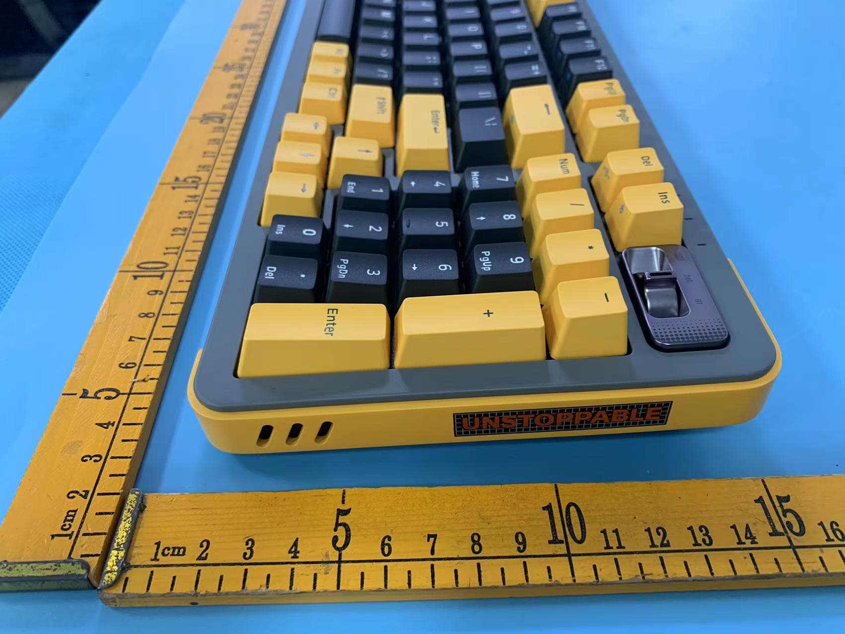
2AXYZ-Y98
Oct 08, 2023Mechanical keyboard
Equipment Class
DSS - Part 15 Spread Spectrum Transmitter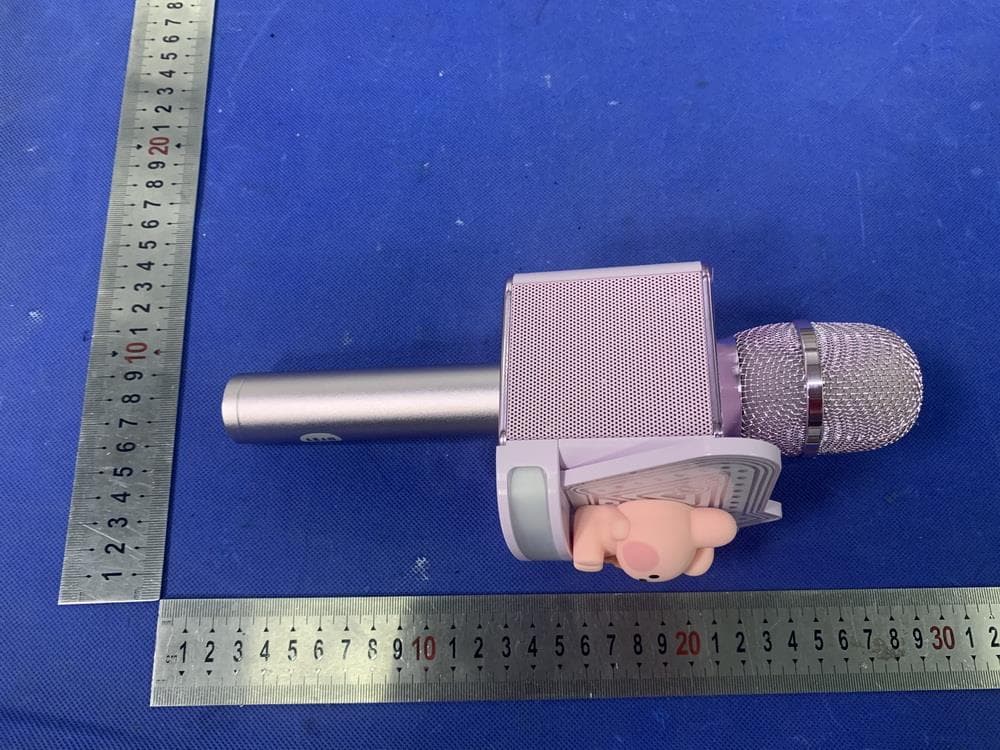
2AXYZ-MININI-RMC
Jun 14, 2022Bluetooth microphone speaker
Equipment Class
DSS - Part 15 Spread Spectrum Transmitter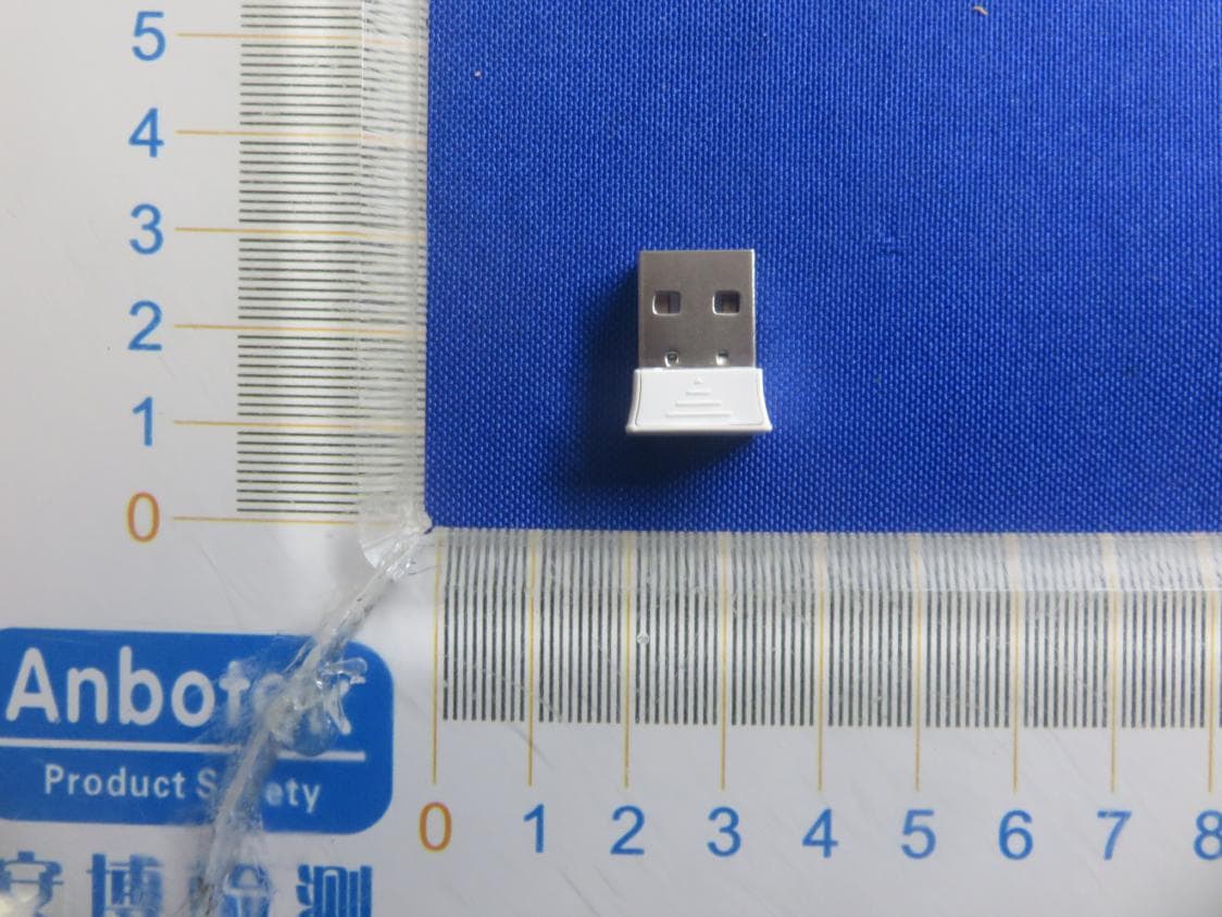
2AXYZ-TAN-RCV
Jul 11, 2021Dongle
Equipment Class
DSS - Part 15 Spread Spectrum Transmitter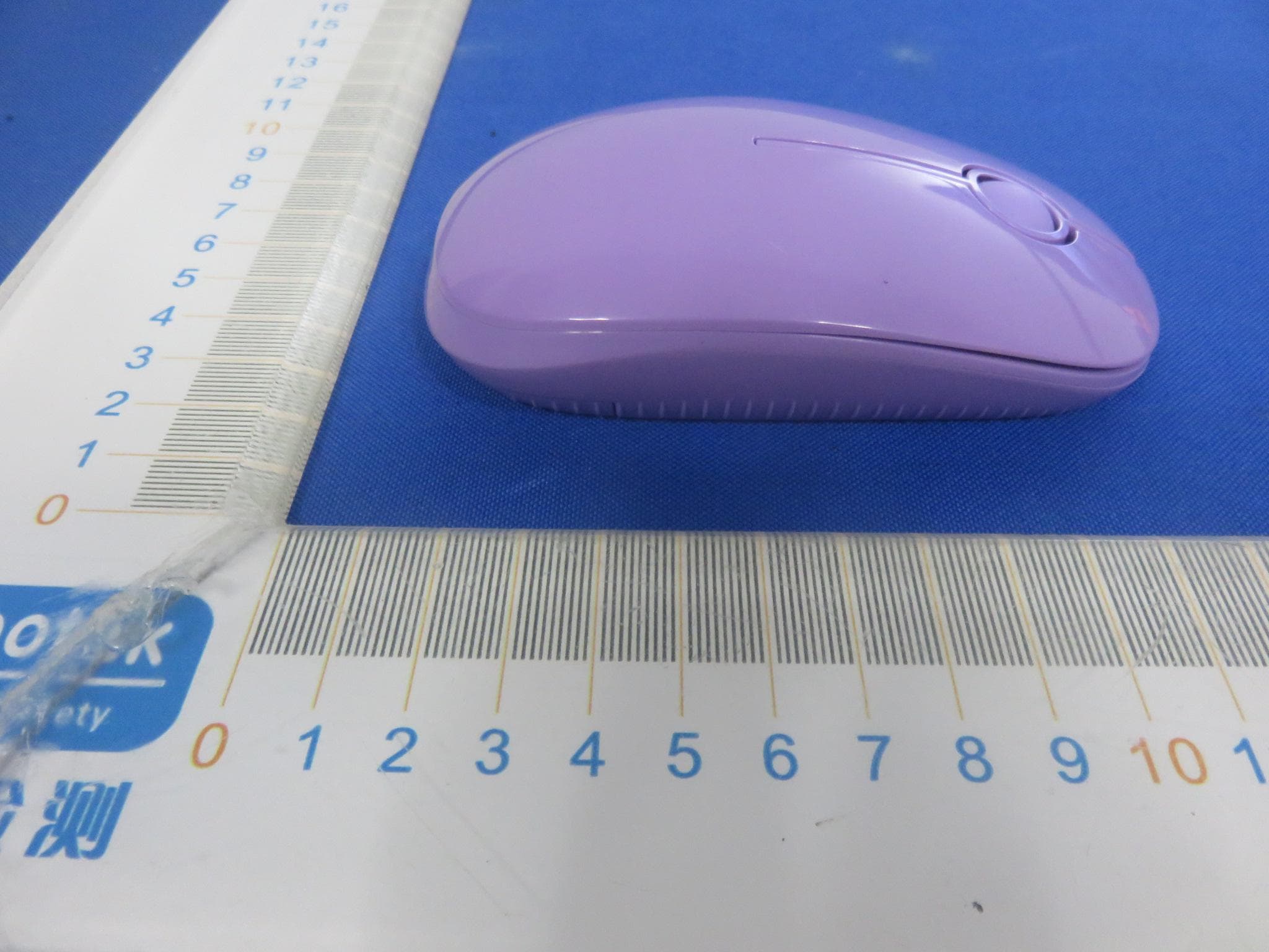
2AXYZ-TAN-RMS
Jul 10, 2021Wireless Mouse
Equipment Class
DSS - Part 15 Spread Spectrum Transmitter