2AY2C-APNA01WIRELESS ACCESS POINT
GrowFlux, Inc.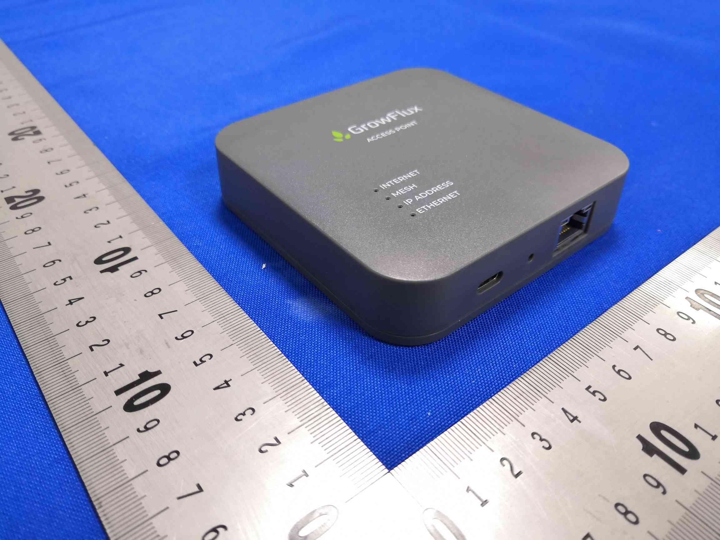
Click to zoom
Application Details
- Equipment Class
- DXX - Part 15 Low Power Communication Device Transmitter
- Date of Grant
- Sep 18, 2022
- Application Purpose
- Original Equipment
- Date of Application
- Sep 17, 2022
- Equipment Note
- WIRELESS ACCESS POINT
- Frequency Range
- 915.00000000 - 915.00000000
- Company
- GrowFlux, Inc.
- Country
- United States
Documents & Files
Document Text
Text extracted from the exhibit documents filed with the FCC. Open a document above to read the original.
Users Manual
Access Point 1 How the Access Point works The GrowFlux Access Point is an always-on wireless device that serves as the foundation for your on-site GrowFlux Mesh, a high reliability wireless mesh for lighting controls, sensing, and other devices. The Access Point functions as a bridge between your GrowFlux Mesh devices and GrowFlux cloud applications. An Android or iOS device is required to set up the Access Point, however any device with any GrowFlux cloud application can be used to interact with devices once the Access Point is set up. 2 What’s in the box 3 Device Overview Inside device: CR2032 Lithium coin cell battery; powers internal clock to keep date and time in the event of power and Internet connectivity loss 4 Quick Start Instructions Quick Start Video Link Requirements: • iOS or Android device with Bluetooth (only needed for initial setup) • Internet connection with 10Base-T Ethernet port • AC power outlet for AC adapter 5 Step 1 Download GrowFlux App • For iOS, search the App Store for ‘GrowFlux’ • For Android, search the Google Play store for ‘GrowFlux’ • Or scan the barcode below or navigate to growflux.com/app on your device. App Link 6 Step 2 Setup GrowFlux App • Create your GrowFlux Account and log in • Ensure your device has Bluetooth permissions enabled for the GrowFlux App Step 3 Plug in power • Plug the supplied USB C power adapter into the Access Point 7 Step 4 Plug in Ethernet. The Access Point should obtain an IP address and connect to the Internet within 30 seconds. Read steps 5-7 if you do not see the 3 LED lights shown below on the Access Point after connecting the Ethernet cable. 8 Step 5 The Ethernet LED indicator should light when an Ethernet cable is plugged in. If the Ethernet LED does not light up, the Access Point is not connected to an active Ethernet port. Link and activity lights on the Ethernet connector should also light. If no LEDs light, check the port on the other end of the Ethernet cable. 9 Step 6 The Access Point should automatically obtain an IP address. The Access Point should obtain an IP address, typically within a few minutes. When the Access Point obtains an IP address, the ‘IP ADDRESS’ LED will light up. Troubleshooting: Make sure DHCP is enabled on your network and wait up to 5 minutes for the Access Point to obtain an IP address. If the Access Point does not obtain an IP address, ask to your network administrator for further assistance. 10 Step 7 The Access Point should automatically connect to the Internet. The ‘INTERNET’ LED will illuminate when the Access Point connects to the Internet. If this LED does not light up, check your Internet connection. Troubleshooting: Check your Internet connection on other devices or contact your Internet Service Provider. 11 Step 8 Associate the Access Point to your GrowFlux Account Bring your Android or iOS device close to the Access Point and follow the instructions in the app to add the Access Point. From the main menu in the GrowFlux App, select ‘Add New Devices’, then select ‘Access Point’. Troubleshooting: Ensure that your Bluetooth connection is turned on and Bluetooth permissions are enabled for the GrowFlux App. If the Access Point fails to associate, try placing your Android or iOS device closer to the Access Point during the association process. 12 The Access Point is now connected and is ready to invite GrowFlux Mesh devices. Use the GrowFlux App or browser based web app to add devices. Note Your Android or iOS device are no longer required to be present with the Access Point. The Access Point is now a bridge between your GrowFlux Mesh products and the GrowFlux Cloud. Control your GrowFlux Mesh products from any Android or iOS device with the GrowFlux App. Alternatively, use the GrowFlux web app on any browser at https://panel.growflux.com 13 Placement tips for optimal wireless connectivity The Access Point offers the most robust wireless connectivity to devices that are within a line of sight, and is generally capable of connecting to devices up to 500 feet away, depending on the device. If possible, place the Access Point in a position that is as close to line of sight to at least one of your always-on (i.e. not battery operated) GrowFlux Mesh devices. Additional GrowFlux Mesh devices that are obstructed or are not in line of sight will receive their connection from nearby devices that are closer to the Access Point. Avoid mounting the Access Point to metal walls or surfaces. If possible, try to mount the Access Point away from metal objects and metal building materials. Avoid placing the Access Point on the ground. 14 Network Requirements The GrowFlux Access Point requires an Ethernet connection to the Internet, and typically does not require any special network configuration or firewall settings. The Ethernet interface on the Access Point requires at minimum a 10Base-T port. The Access Point requires DHCP (Dynamic Host Configuration Protocol) in order to obtain an IP address. DHCP is typically enabled on most consumer and commercial networks. 15 Network FAQ Are any special networking requirements necessary for the Access Point to function? The GrowFlux Access Point is designed to work with a broad range of commercial and consumer Ethernet networks. If you can plug in a notebook computer and access the Internet without any special configuration, you can connect the Access Point without any additional configuration. If your network requires manual DHCP configuration, you should contact your network administrator for help. These types of configurations are rare. I have a firewall - what do I need to do? The GrowFlux Access Point is designed to work with all common firewall configurations and only uses outbound connections on port 443, so firewalls are typically not an issue. 16 Is the Access Point secure? All wireless communications are AES128 encrypted. All Ethernet communications are SSL encrypted. Bluetooth configuration can only be activated during initial device setup, and can only …
Text truncated - open the document above for the full version.
Cover Letter(s)
DATE:2022-9-5 Equipment Autorisation Division Federal Communications Commission 7435 Oakland Mills Road Columbia, MD 21046 FCC ID: 2AY2C-APNA01 Product Name: WIRELESS ACCESS POINT Request for Confidentiality Pursuant to Sections 0.457 and 0.459 of the commissions rules, we hereby request that the following documents be held confidential: (List here the documents for which you are seeking confidentiality – for example ...) •Schematics •Block diagram •Operati on description These materials contain trade secrets and proprietary information and are not customarily released to the public. The public disclosure of this information might be harmful to the company and provide unjustified benefits to our competitors. <Signature> Name:Eric Eisele Title:Manager Applicant Company:GrowFlux, Inc
Cover Letter(s)
DATE:2022-9-5 FederalCommunicationsCommission Authorization&EvaluationDivision 7345OaklandMillsRoad Columbia,Maryland21046 AuthoritytoActasAgent Onourbehalf,IappointBlueAsiaofTechnicalServices(Shenzhen)Co.,Ltd. BuildingC,No.107,ShihuanRoad,ShiyanSub-District,BaoanDistrict,Shenzhen, GuangdongProvince,China(NameofAgentcompanynameandaddress)toactasour agentinthepreparationofthisapplicationforequipmentcertification.Icertifythatsubmitted documentsproperlydescribethedeviceorsystemforwhichequipmentcertificationissought. Ialsocertifythateachunitmanufactured,importedormarketed,asdefinedintheFederal CommunicationsCommission’sregulationswillhaveaffixedtoitalabelidenticaltothat submittedforapprovalwiththisapplication.Forinstanceswhereourauthorizedagentsigns theapplicationforcertificationonourbehalf,Iacknowledgethatallresponsibilityfor complyingwiththetermsandconditionsforcertification,stillresideswithGrowFlux,Inc./3401 MarketStSTE200PhiladelphiaPennsylvaniaUnitedStates (ApplicantNameandaddress) <Signature> Name:EricEisele Title:Manager ApplicantCompany:GrowFlux,Inc
External Photos
ProductName: WIRELESSACCESSPOINT
ID Label/Location Info
Access Point Model Number: GFX-AP-NA HVIN: 2.4 FVIN: GFX-AP-V2 Device serial: XX:XX:XX:XX:XX:XX:XX:XX Ethernet MAC: XX:XX:XX:XX:XX:XX FCC ID: 2AY2C-APNA01 IC: 27912-APNA01 https://panel.growflux.com This device complies with part 15 of the FCC Rules. Operation is subject to the following two conditions: (1) This device may not cause harmful interference, and (2) this device must accept any interference received, including interference that may cause undesired operation. USB PD 5V 0.5A Developed in USA Made in China RoHS
Internal Photos
ProductName: WIRELESSACCESSPOINT
Test Report
Page 1 of 36 BlueAsiaofTechnicalServices(Shenzhen)Co.,Ltd. Add:BuildingC,No.107,ShihuanRoad,ShiyanSub-District,BaoanDistrict,Shenzhen,GuangdongProvince,China Tel:+86-755-23059481Email:[email protected] TESTREPORT ProductName: WIRELESSACCESSPOINT BrandMark: N/A ModelNo.: GFX-AP-NA FCCID: 2AY2C-APNA01 ReportNumber: BLA-EMC-202204-A8103 DateofSampleReceipt: 2022/4/21 DateofTest: 2022/4/21to2022/9/14 DateofIssue: 2022/9/14 TestStandard: 47CFRPart15,SubpartC15.249 TestResult:Pass Preparedfor: GrowFlux,Inc. 3401MarketStSTE200PhiladelphiaPennsylvaniaUnitedStates Preparedby: BlueAsiaofTechnicalServices(Shenzhen)Co.,Ltd. BuildingC,No.107,ShihuanRoad,ShiyanSub-District,BaoanDistrict, Shenzhen,GuangdongProvince,China TEL:+86-755-23059481 Compiledby:Reviewby: Approvedby:Date:2022/9/14 ReportNo.:BLA-EMC-202204-A8103 Page 2 of 36 BlueAsiaofTechnicalServices(Shenzhen)Co.,Ltd.Tel:+86-755-23059481Email:[email protected] REPORTREVISERECORD VersionNo.DateDescription 002022/9/14Original ReportNo.:BLA-EMC-202204-A8103 Page 3 of 36 BlueAsiaofTechnicalServices(Shenzhen)Co.,Ltd.Tel:+86-755-23059481Email:[email protected] TABLEOFCONTENTS 1TESTSUMMARY........................................................................................................................................5 2GENERALINFORMATION.........................................................................................................................6 3GENERALDESCRIPTIONOFE.U.T..........................................................................................................6 4TESTENVIRONMENT................................................................................................................................7 5TESTMODE................................................................................................................................................7 6MEASUREMENTUNCERTAINTY..............................................................................................................7 7DESCRIPTIONOFSUPPORTUNIT..........................................................................................................8 8LABORATORYLOCATION.........................................................................................................................8 9TESTINSTRUMENTSLIST........................................................................................................................9 10RADIATEDEMISSIONS............................................................................................................................12 10.1LIMITS................................................................................................................................................................12 10.2BLOCKDIAGRAMOFTESTSETUP......................................................................................................................13 10.3PROCEDURE.......................................................................................................................................................13 10.4TESTDATA...........................................................................................................................................................14 11RESTRICTEDBANDAROUNDFUNDAMENTALFREQUENCY...........................................................18 11.1LIMITS................................................................................................................................................................18 11.2BLOCKDIAGRAMOFTESTSETUP......................................................................................................................19 11.3PROCEDURE.......................................................................................................................................................19 11.4TESTDATA...........................................................................................................................................................21 12FIELDSTRENGTHOFTHEFUNDAMENTALSIGNAL(15.249(A)).......................................................23 12.1LIMITS................................................................................................................................................................23 12.2BLOCKDIAGRAMOFTESTSETUP......................................................................................................................24 12.3PROCEDURE.......................................................................................................................................................24 12.4TESTDATA...........................................................................................................................................................26 1320DBBANDWIDTH...................................................................................................................................27 13.1LIMITS................................................................................................................................................................27 13.2BLOCKDIAGRAMOFTESTSETUP......................................................................................................................27 1.1TESTDATA................................................................................................................................................................27 1.2TESTPLOTS................................................................................................................................................................28 14CONDUCTEDEMISSIONSATACPOWERLINE(150KHZ-30MHZ).....................................................29 ReportNo.:BLA-EMC-202204-A8103 Page 4 of 36 BlueAsiaofTechnicalServices(Shenzhen)Co.,Ltd.Tel:+86-755-23059481Email:[email protected] 14.1LIMITS.......................................................................................................…
Text truncated - open the document above for the full version.
Test Report
Design Note DN024 SWRA227E Page 1 of 16 Monopole PCB Antenna with Single or Dual Band Option By Richard Wallace Keywords Single Band Mode (868 MHz, 915 MHz or 920 MHz) Dual Band Mode (868 MHz & 2440 MHz) PCB Antenna Monopole Antenna Excellent Efficiency Recommended Antenna Design for 868 MHz, 915 MHz & 920 MHz OTA Measurements 1 Introduction This document describes a PCB antenna that can be configured in two different modes of operation: the antenna can be tuned for a single frequency for operation in the 868 MHz (Europe), 915 MHz (USA) and 920 MHz (Japan) ISM bands; or the antenna can be configured as a dual band antenna which can operate at 868 MHz and 2440 MHz. This antenna can be used with all transceivers and transmitters from Texas Instruments which operates in these frequency bands. Overall size requirements for this antenna are 38 x 25 mm. Thus this is a medium size, low cost antenna solution. Figure 1 shows a picture the board being used to develop and characterize this antenna. This antenna design is one of the several antenna reference designs available on www.ti.com/lpw and is included in the Comprehensive Antenna Selection Guide [6] and the Antenna Selection Quick Guide [7]. Figure 1. CC-Antenna-DK, Board #6 PCB Monopole Antenna Design Note DN024 SWRA227E Page 2 of 16 Table of Contents KEYWORDS 1 1 INTRODUCTION 1 2 ABBREVIATIONS 2 3 DESCRIPTION OF THE PCB ANTENNA 3 3.1 IMPLEMENTATION OF THE MEANDERING MONOPOLE ANTENNA 3 4 RESULTS 5 4.1 RADIATION PATTERN 5 4.2 SINGLE BAND OPTION DESIGN FOR 868 / 915 / 920 MHZ 6 4.2.1 Antenna Match 6 4.2.1.1 Smith Chart – No Antenna Match Components 6 4.2.1.2 Theoretical Smith Chart Match 7 4.2.2 Bandwidth 8 4.3 DUAL BAND OPTION DESIGN FOR 868 & 2440 MHZ 9 4.3.1 Antenna Match 9 4.3.1.1 Smith Chart – No Antenna Match Components 9 4.3.2 Bandwidth 12 4.4 OTA MEASUREMENT SUMMARY 13 5 CONCLUSION 14 6 REFERENCES 15 7 DOCUMENT HISTORY 16 2 Abbreviations AUT Antenna Under Test BOM Bill Of Materials BW Bandwidth CF Correction Factor CITA Cellular Telecommunications Industry Association DK Development Kit EB Evaluation Board EIRP Effective Isotropic Radiated Power EM Evaluation Module ISM Industrial, Scientific, Medical NC Not Connected NHPRP Near Horizon Partial Radiated Power NHPRP45 Near Horizon Partial Radiated Power within 45 degrees angle OTA Over The Air PCB Printed Circuit Board RF Radio Frequency SWR Standing Wave Ratio TRP Total Radiated Power Design Note DN024 SWRA227E Page 3 of 16 3 Description of the PCB Antenna The antenna described in this document is a meandering monopole. The impedance of this antenna depends on the mode used. Referring to Figure 2, if the length of L4 is kept as shown then this is beneficial for the Dual Band Mode. If L4 is shortened to the silkscreen marking, then this is beneficial for the Single Band Mode. It is recommended to use a pi-matching network at the feed point of the antenna as shown in Figure 2 since the geometry of the ground plane affects the impedance of the antenna. The pi- network can be used to compensate for detuning caused by plastic encapsulation and other objects in close vicinity of the antenna. For further information on impedance matching and impedance measurements, see AN058 [6]. The antenna layout is positioned on the top and bottom layer of the board; this enables a lower resistive loss and gives a slightly wider bandwidth compared to a single sided layout solution. With a single sided layout; the area underneath the antenna can not be used for any other routing so it is more useful to utilize this area to optimize the antenna’s performance. 3.1 Implementation of the Meandering Monopole Antenna To obtain optimum performance it is important to make an exact copy of the antenna dimensions. The antenna was implemented on a 1.6 mm thick FR4 substrate. Since there is no ground plane beneath the antenna the PCB thickness is not critical, but if a different thickness is being used it will be necessary to change the matching network to obtain optimum performance. One approach to implement the antenna in a PCB CAD tool is to import the antenna layout from a Gerber file. Such a file is included in the CC-Antenna-DK Reference Design [8]. The CC-Antenna-DK contains 16 different board designs [1] and the gerbers from board 6 can be copied for this antenna design. If the antenna is implemented on a PCB that is wider than the antenna it is important to avoid placing components or having a ground plane close to each side of the antenna. If the CAD tool being used does not support import of Gerber files, Figure 2 and Table 1 can be used. Design Note DN024 SWRA227E Page 4 of 16 Figure 2. Antenna Dimensions L1 9.0 mm Y 43.0 mm L2 18.0 mm X1 63.0 mm L3 3.0 mm X2 25.0 mm L4 38.0 mm W 2.0 mm L5 1.0 mm Table 1. Antenna Dimensions Optimum length for the last antenna segment is dependent on the geometry of the ground plane. The antenna can also be used for 915 & 920 MHz. For larger ground planes L4 would have to be further reduced or the antenna match re-calculated. Design Note DN024 SWRA227E Page 5 of 16 4 Results The CTIA measurement summary results are presented in this section. Note that the performance will be affected by the size and shape of the ground plane. 4.1 Radiation Pattern Figure 3 and Figure 4 shows how to relate the radiation patterns in this section to the orientation of the antenna. A link to the full measurement report is included in the measurement summary. For reference purposes; measurements have also been performed on the standard whip SMA antennas that are supplied with the EM boards [3], [4]. Note that the size of the ground plane will affect the radiation pattern. Thus implementing this antenna on a board with a different size and shape of the ground plane will most likely affect the radiation pattern. Figure 3. Coordinates for the Radiation Patterns when used as a stand alone board Figure 4. Coordinates for the Radiation Patterns when used with the EM & EB Design Note DN02…
Text truncated - open the document above for the full version.
Test Setup Photos
ProductName: WIRELESSACCESSPOINT ConductedEmissionsatACPowerLine(150kHz-30MHz) RadiatedSpuriousEmissions
Contact Information
Applicant
Eric J Eisele(CEO)
Test Firm
BlueAsia of Technical Services (Shenzhen)Blue Zheng
[email protected]+86 755-23059481-815
Technical Specifications
| # | Rule Parts | Frequency Range | Power Output |
|---|---|---|---|
| 1 | 15C | 915 MHz - 915 MHz | - |