2AY43-CCMX11MedRadio
Impulse Dynamics USA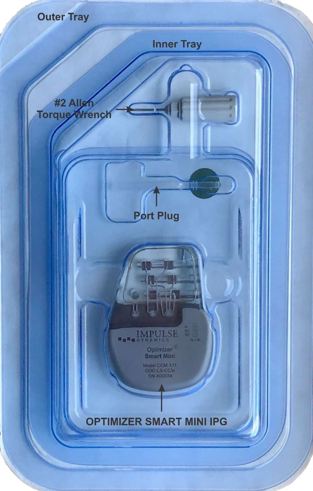
Click to zoom
Application Details
- Equipment Class
- TNT - Licensed Non-Broadcast Transmitter Worn on Body
- Date of Grant
- May 04, 2021
- Application Purpose
- Original Equipment
- Date of Application
- May 04, 2021
- Equipment Note
- MedRadio
- Frequency Range
- 402.00000000 - 405.00000000
- Company
- Impulse Dynamics USA
- Country
- United States
Documents & Files
Document Text
Text extracted from the exhibit documents filed with the FCC. Open a document above to read the original.
Users Manual
Part No.: 13-290-011-US Rev. 00 OPTIMIZER ® Smart Mini Implantable Pulse Generator INSTRUCTIONS FOR USE Impulse Dynamics (USA) Inc. Suite 100 50 Lake Center Executive Parkway 401 Route 73 N Bldg. 50 Marlton, NJ 08053-3425 CCM™ is a trademark of Impulse Dynamics. OPTIMIZER ® is a US registered trademark property of Impulse Dynamics The information provided in this document may change without prior notice. No part of this manual may be reproduced or transmitted in any form or by any method, including electronic and mechanical means, without prior written express consent from Impulse Dynamics. The OPTIMIZER Smart Mini system and the CCM technology are protected by several U.S. Patents. For an up-to-date list of relevant patents and patent applications, visit our patents page: http://www.impulse- dynamics.com/us/patents Please read the complete documentation provided before you use the device. Revision 0, Date of Issue: 2021-01-22 i TABLE OF CONTENTS EXPLANATION OF SYMBOLS ON LABELS .......................................................................................... I 1.0 THE OPTIMIZER SMART MINI SYSTEM ................................................................................... 1 1.1 Description of the OPTIMIZER Smart Mini System ......................................................... 1 1.2 OPTIMIZER Smart Mini IPG Implantable Leads Requirements ....................................... 1 1.3 OPTIMIZER Smart Mini IPG Lead Connectors ............................................................... 2 1.4 OPTIMIZER Smart Mini IPG Physical Characteristics ..................................................... 3 1.5 OPTIMIZER Smart Mini IPG Battery ............................................................................... 3 1.5.1 Battery Specifications ........................................................................................ 3 1.5.2 Battery Behavior ................................................................................................ 4 1.5.3 Battery Service Life ............................................................................................ 4 1.6 OPTIMIZER Smart Mini IPG Packaging .......................................................................... 4 1.7 OPTIMIZER Smart Mini IPG Storage .............................................................................. 4 2.0 USER PROFILE AND TRAINING ............................................................................................... 5 3.0 INDICATIONS OF USE .............................................................................................................. 5 4.0 CONTRAINDICATIONS AND PRECAUTIONS ........................................................................... 5 5.0 WARNINGS................................................................................................................................ 5 5.1 Potential Complications of Device Implantation ............................................................... 5 5.1.1 Atrial and Ventricular Arrhythmias Potentially Caused by Lead Implantation ....... 6 5.1.2 Ventricular Arrhythmias Potentially Caused by CCM therapy pulses ................... 6 5.1.3 Atrial Arrhythmias Potentially Caused by CCM Therapy Pulses .......................... 7 5.2 Electrocautery ................................................................................................................ 7 5.3 RF Ablation .................................................................................................................... 8 5.4 Diathermy (Medical “Short Wave” Induction Heating) ...................................................... 8 5.5 Defibrillation and Cardioversion ...................................................................................... 8 5.6 Therapeutic Ultrasound .................................................................................................. 9 5.7 Nuclear Magnetic Resonance (NMR), Magnetic Resonance Imaging (MRI) .................... 9 5.8 Radiation Therapy .......................................................................................................... 9 5.9 Lithotripsy ...................................................................................................................... 9 5.10 Handling ....................................................................................................................... 10 5.11 Resterilization and Reuse ............................................................................................. 10 5.12 Cremation .................................................................................................................... 10 6.0 CAUTIONS ............................................................................................................................... 10 6.1 Environmental Conditions ............................................................................................. 10 6.2 Transcutaneous Electrical Nerve Stimulation (TENS) ................................................... 10 6.3 Home Appliances ......................................................................................................... 11 6.4 Store Anti-Theft Systems/Airport Security Screening Systems ...................................... 11 6.5 Industrial Machinery ..................................................................................................... 11 ii 6.6 Transmitting Devices .................................................................................................... 11 6.7 Cellular and Mobile Phones .......................................................................................... 11 7.0 POTENTIAL ADVERSE EFFECTS ........................................................................................... 12 8.0 DEVICE IMPLANTATION ......................................................................................................... 13 8.1 General Considerations .....................................…
Text truncated - open the document above for the full version.
Cover Letter(s)
3/23/2021 Impulse Dynamics USA Inc. 50 Lake Center Executive Parkway 401 Route 73N, Bldg. 50, Suite 100 Marlton, NJ 08053-3449 Professional Testing (EMI) Inc. 1601 N. A.W. Grimes Blvd, Suite B Round Rock, TX 78665 To whom it may concern: This letter authorizes Eric Lifsey of Profession Testing (EMI) Inc. as agent for Impulse Dynamics USA Inc. regarding all matters relating to applications for equipment authorization, including signing of all documents relating to these matters to FCC certification for FCC ID 2AY43-CCMX11 for Impulse Dynamics’ Optimizer Smart Mini. This authorization is effective until September 23, 2021. Sincerely, Jordan Thimot, Ph.D. Impulse Dynamics USA Inc. Product Development Engineer
Cover Letter(s)
3/23/2021 Impulse Dynamics USA Inc. 50 Lake Center Executive Parkway 401 Route 73N, Bldg. 50, Suite 100 Marlton, NJ 08053-3449 Federal Communications Commission Equipment Authorization Branch 7435 Oakland Mills Road Columbia, MD 21046 Confidentiality Request FCC ID: 2AY43-CCMX11 Pursuant to Sections 0.457(d)(1)(ii) and 0.459 of the Commission’s Rules, Impulse Dynamics USA Inc. hereby requests permanent confidential treatment of information accompanying this application as outlined below: Schematics Bill of Materials/Parts List Block Diagrams Operational Description Impulse Dynamics USA Inc. also hereby requests short-term confidential treatment of information accompanying this application as outlined below for a period of period of 180 days: Internal Photos External Photos User Manual Test Set-up Photographs The above materials contain trade secrets and proprietary information not customarily released to the public. The public disclosure of these matters might be harmful to the Applicant and provide unjustified benefits to its competitors. The Applicant understands that pursuant to Rule 0.457(d)(1)(ii), disclosure of this Application and all accompanying materials will not be made before the date of the Grant for this Application. Sincerely, Jordan Thimot, Ph.D. Impulse Dynamics USA Inc. Product Development Engineer
External Photos
External Picture 1: Picture of the Optimizer Smart Mini. External Picture 2: Computer generated model showing dimensions and volume of implant. Dimensional units are in millimeters, and volume units are in cubic centimeters. External Picture 3: Picture of Optimizer Smart Mini in hermetically sealed packaging.
ID Label/Location Info
Engraving: Picture of the Optimizer Smart Mini IPG case engraving. Main Label: Label placed on the external packaging of the Optimizer Smart Mini IPG.
Internal Photos
Internal Picture 1: PCB layout of the Optimizer Smart Mini in cannister during production, prior to header attachment Internal Picture 2: PCB layout of the back side of Optimizer Smart Mini prior to tab release and placement into cannister. Internal Picture 3: Feedthrough lines connecting epoxy header with antenna and standard lead connections to Smart Mini PCB and cannister.
RF Exposure Info
Project 21613-15 CCC del Uruguay S.A. Cardiac Implantable Optimizer Smart Mini Test Report Exposure Medical Device Radio Communications Service Prepared for: CCC del Uruguay S.A General Paz 1363 Montevideo, Uruguay 11400 By Professional Testing (EMI), Inc. 1601 North A.W. Grimes Blvd., Suite B Round Rock, Texas 78665 8 Apr 2021 Eric Lifsey EMC Engineer Cardiac Implantable Medical Radio 21613-15 Professional Testing (EMI) Inc. Page 2 of 6 Revision History Revision Number Description Date Final 8 Apr 2021 Errata: None. Cardiac Implantable Medical Radio 21613-15 Professional Testing (EMI) Inc. Page 3 of 6 Table of Contents Revision History ............................................................................................................................................................ 2 Certificate of Compliance ............................................................................................................................................. 4 1.0 Introduction .......................................................................................................................................................... 5 1.1 Scope ............................................................................................................................................................... 5 1.2 EUT Description ............................................................................................................................................. 5 2.0 Permissible Exposure Evaluation 95.2585 ........................................................................................................... 6 2.1 Procedure ........................................................................................................................................................ 6 2.2 Limits .............................................................................................................................................................. 6 2.3 Results ............................................................................................................................................................. 6 End of Report ................................................................................................................................................................ 6 NOTICE: (1) This Report must not be used to claim product endorsement, by NVLAP, NIST, the FCC or any other Agency. This report also does not warrant certification by NVLAP or NIST. (2) This report shall not be reproduced except in full, without the written approval of Professional Testing (EMI), Inc. (3) The significance of this report is dependent on the representative character of the test sample submitted for evaluation and the results apply only in reference to the sample tested. The manufacturer must continuously implement the changes shown herein to attain and maintain the required degree of compliance. Cardiac Implantable Medical Radio 21613-15 Professional Testing (EMI) Inc. Page 4 of 6 Certificate of Compliance FCC MRA Designation Number: US5270 NVLAP Accreditation Number: 200062-0 Applicant Device & Test Identification CCC del Uruguay S.A. Gral Paz 1363 Montevideo, Uruguay 11400 Certificate Date: 8 Apr 2021 Model(s): Cardiac Implantable Optimizer Smart Mini Laboratory Project ID: 21613-15 (22421) The EUT(s) listed above were tested utilizing the following documents and found to be in compliance with the required criteria. FCC Part 95 Subpart I Medical Device Radio Communications Service Test Class/Limits Met Test Level Test Date Permissible Exposure Evaluation 95.2585 Complies 1.1307(b) and 2.1093 exposure limit satisfied 26 Jun 2020 This report has been reviewed and accepted by the Applicant. The undersigned is responsible for ensuring that this device will continue to comply with the rules listed above. _____________________________________ Representative of Applicant Cardiac Implantable Medical Radio 21613-15 Professional Testing (EMI) Inc. Page 5 of 6 1.0 Introduction 1.1 Scope This report describes the extent to which the equipment under test (EUT) conformed to the exposure limits of the USA. 1.2 EUT Description This device is a wireless controlled implantable pulse generator for medical applications. Table 1.2.1: Equipment Under Test Manufacturer Model Description CCC del Uruguay S.A. Cardiac Implantable Optimizer Smart Mini Medical Radio Transceiver Cardiac Implantable Medical Radio 21613-15 Professional Testing (EMI) Inc. Page 6 of 6 2.0 Permissible Exposure Evaluation 95.2585 2.1 Procedure The human exposure is determined using the transmit power as weighed per the operational transmission time required. 2.2 Limits Requirement Limits Radiofrequency radiation exposure requirements specified in §§ 1.1307(b) and 2.1093. ≤1.0 mW* SAR exclusion per FCC KDB 447498. 47 CFR § 1.1307 (b)(2)(iv) Equipment authorized for use in the Medical Device Radiocommunication Service (MedRadio) as a medical implant device or body-worn transmitter (as defined in subpart I of part 95 of this chapter) is subject to routine environmental evaluation for RF exposure prior to equipment authorization, as specified in §§ 2.1093 and 95.2585 of this chapter by finite difference time domain (FDTD) computational modeling or laboratory measurement techniques. [...] 47 CFR § 2.1093 (c)(1) Portable devices [...] the Medical Device Radiocommunication Service (MedRadio), and [...] are subject to routine environmental evaluation for RF exposure prior to equipment authorization or use. *FCC 447498 D01 General RF Exposure Guidance v06: Paragraph 4.2.4. Transmitters implanted in the body of a user When the aggregate of the maximum power available at the antenna port and radiating structures of an implanted transmitter, under all operating circumstances, is ≤ 1.0 mW, SAR test exclusion may be applied. The maximum available output power requirement and worst case operating conditions must be supported by power measurement results,…
Text truncated - open the document above for the full version.
Test Report
Project 21613-15 CCC del Uruguay S.A. Cardiac Implantable Optimizer Smart Mini Test Report FCC Part 95 Subpart I Medical Device Radio Communications Service Prepared for: CCC del Uruguay S.A General Paz 1363 Montevideo, Uruguay 11400 By Professional Testing (EMI), Inc. 1601 North A.W. Grimes Blvd., Suite B Round Rock, Texas 78665 24 Aug 2020 5 May 2021 Reviewed by Written by Larry Finn Chief Technical Officer Eric Lifsey EMC Engineer Cardiac Implantable Medical Radio 21613-15 Professional Testing (EMI) Inc. Page 2 of 31 Revision History Revision Number Description Date Draft 2 Draft for review. 3 Sep 2020 Final 5 Nov 2020 Final Rev01 Additional standards reference (1.6), setup detail (1.8), and measurement clarification (4.3) per TCB comments. Test data unchanged. 5 May 2021 Errata: None. Cardiac Implantable Medical Radio 21613-15 Professional Testing (EMI) Inc. Page 3 of 31 Table of Contents Revision History ............................................................................................................................................................ 2 Certificate of Compliance ............................................................................................................................................. 4 1.0 Introduction .......................................................................................................................................................... 5 1.1 Scope ............................................................................................................................................................... 5 1.2 EUT Description ............................................................................................................................................. 5 1.3 EUT Operation ................................................................................................................................................ 5 1.4 Modifications to Equipment ............................................................................................................................ 5 1.5 Test Site .......................................................................................................................................................... 5 1.6 Applicable Documents and Clauses ................................................................................................................ 6 1.7 Deviations ....................................................................................................................................................... 6 1.8 Torso Simulator .............................................................................................................................................. 6 2.0 Duration of Transmissions 95.2557 and Frequency Monitoring 95.2559 ............................................................ 8 2.1 Procedure ........................................................................................................................................................ 8 2.2 Limits .............................................................................................................................................................. 8 2.3 Results ............................................................................................................................................................. 8 3.0 Frequency Accuracy 95.2565 ............................................................................................................................ 10 3.1 Procedure ...................................................................................................................................................... 10 3.2 Limits ............................................................................................................................................................ 10 3.3 Results ........................................................................................................................................................... 10 3.3.1 Equipment ........................................................................................................................................... 11 3.3.2 Photographs ......................................................................................................................................... 11 4.0 EIRP 95.2567 and Field Strength 95.2569 ......................................................................................................... 12 4.1 Procedure ...................................................................................................................................................... 12 4.2 Limits ............................................................................................................................................................ 12 4.3 Results ........................................................................................................................................................... 12 4.3.1 Equipment ........................................................................................................................................... 13 4.3.2 Photographs ......................................................................................................................................... 13 5.0 Bandwidth 95.2573 ............................................................................................................................................ 15 5.1 Procedure ...................................................................................................................................................... 15 5.2 Limits ............................................................................................................................................................ 15 5.3 Results ..............................................................................................................................…
Text truncated - open the document above for the full version.
Test Setup Photos
22421 (21613-15) Setup Photos Page 1 of 5 Radiated Emissions, Front Radiated Emissions, Rear Stability, EUT Stability, Setup Bandwidth EUT Outside Torso Simulator for Reference Measurement EUT Inside Torso Simulator for Loss Measurement Side View of EUT in Torso Simulator EUT Surface Spacing Measurement ***
Contact Information
Applicant
Dr. David Prutchi(CTO and Executive Vice President)
Test Firm
Professional Testing (EMI), Inc.Larry Finn
Technical Specifications
| # | Rule Parts | Frequency Range | Power Output | Emission | Tolerance |
|---|---|---|---|---|---|
| 1 | 95I | 402 MHz - 405 MHz | 0.80 µW | 247KG1D | 100.0000000000 ppm |