2AY4L-CUESTICKERSmart Pack
CuePath Innovation Inc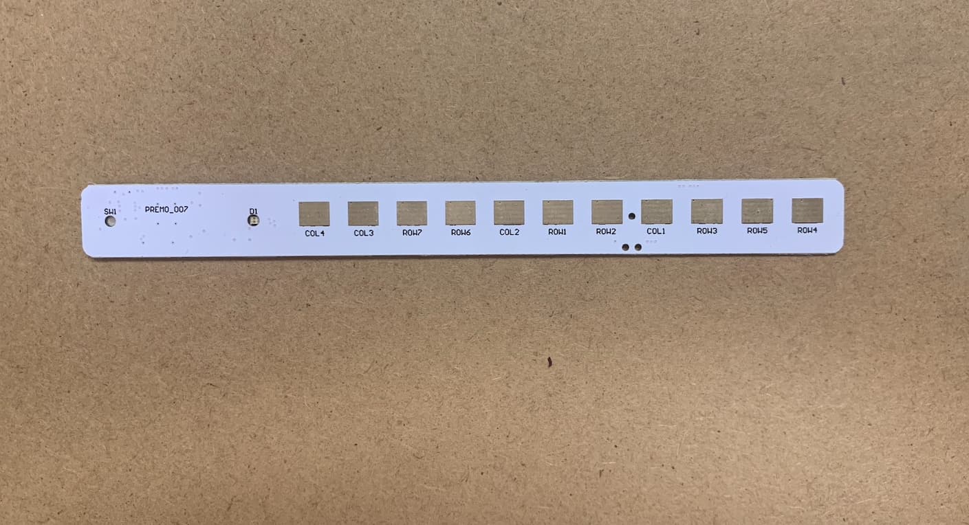
Click to zoom
Application Details
- Equipment Class
- DTS - Digital Transmission System
- Date of Grant
- May 05, 2021
- Application Purpose
- Original Equipment
- Date of Application
- May 05, 2021
- Equipment Note
- Smart Pack
- Frequency Range
- 2402.00000000 - 2480.00000000
- Company
- CuePath Innovation Inc
- Country
- Canada
Documents & Files
Document Text
Text extracted from the exhibit documents filed with the FCC. Open a document above to read the original.
Users Manual
TWI FW 16-02 REV 0.2 TWI Cuepath Firmware Behavior Thirdwayv Inc. Proprietary and Confidential Page 1 of 5 General Description This document describes the firmware behavior of the CuePath system. Contents General Description ............................................................................................................................................................ 1 Documents Referenced ....................................................................................................................................................... 2 1 Introduction ........................................................................................................................................................ 3 2 CuePath Device (Smart Pack) Behavior ............................................................................................................... 3 2.1 Production Test Mode ......................................................................................................................................... 3 2.2 Pharmacy Activation Mode ................................................................................................................................. 3 Revision History ................................................................................................................................................................... 5 Contact Information ............................................................................................................................................................ 5 FCC and IC NOTICES: ........................................................................................................................................................... 6 TWI FW 16-02 REV 0.2 TWI Cuepath Firmware Behavior Thirdwayv Inc. Proprietary and Confidential Page 2 of 5 Documents Referenced Number Title [1] [TWI 16-08] CueCare Tester Application User Manual TWI FW 16-02 REV 0.2 TWI Cuepath Firmware Behavior Thirdwayv Inc. Proprietary and Confidential Page 3 of 5 1 Introduction This document describes the CuePath device Firmware behavior. 2 CuePath Device (Smart Pack) Behavior 1. The device has a push button and 2 LEDs (RED and Green). 2. The device starts in the Deep Sleep State (Shelf Mode). The device could wakeup only by pressing the push button. 3. The device has two modes of operations; the Production Test Mode and the Pharmacy Activation Mode. 2.1 Production Test Mode 1. The production test mode is used to verify the device hardware components. i.e., the push button, the two LEDs, and the resistor matrix connections. 2. By default, the device works in the production test mode. 3. To verify the push button and LED hardware connections, the user short press the push button. 4. With the user’s button short press, the device blinks red and green LEDs simultaneously once. The user sees an orange color from the LEDs, as both LEDs are ON simultaneously. 5. To initiate the resistor matrix verification procedure, the user has to short press the push button THREE consecutive times. 6. The device counts the short presses when the time among consecutive presses is less than 3 seconds. In other words, if the user takes more than 3 seconds to press the button twice, the device neglects the previous press count and start over. 7. After THREE short presses, the device measures the resistor matrix values. It then compares their values with the expected resistor range to detect whether the packs are opened, disconnected, or closed. a. The test passes when all resistors are connected and closed. In this case, The device turns the GREEN LED on for 5 seconds. b. The test fails when one of the resistors or more are disconnected or opened. In this case, The device turns the RED LED on for 5 seconds. 8. The device advertises the test result for 30 seconds. The test result includes the resistor matrix status, the battery value, and the device’s unique id. The user could use the CueCare Test App to check the device test result. For more information, please check [1] document for further details. 9. After the 30 seconds of advertising, the device returns to the deep sleep state (Shelf mode). 2.2 Pharmacy Activation Mode 1. The pharmacy activation mode is the customer mode. In this mode, the device continuously checks the resistor matrix value and updates the CueCare App with its results. 2. To start the pharmacy activation mode, the user has to long-press the button for 3 seconds. 3. When the pharmacy activation mode starts, The device blinks the green LED FOUR times and then turns the green LED on for 5 seconds. 4. The device measures the resistor matrix, and the battery voltage every 10 mins periodically. When one of the below parameters change between the current and the previous measurements, the device stores the measurement into its internal flash memory and starts advertising with the updated status: TWI FW 16-02 REV 0.2 TWI Cuepath Firmware Behavior Thirdwayv Inc. Proprietary and Confidential Page 4 of 5 a. The resistor matrix status changes. b. The battery voltage decreased by 0.1 volts. c. The battery voltage is below 2.3 volts. 5. The device has a 3 hours keep-alive timer to initiate advertising even if there is no status change. 6. The CueCare App connects to the device automatically whenever the device advertises to read the resistor matrix status updates. TWI FW 16-02 REV 0.2 TWI Cuepath Firmware Behavior Thirdwayv Inc. Proprietary and Confidential Page 5 of 5 Revision History Revision Date Modified By Changes Rev 0.1 Dec 14 th , 2020 Ahmed Zaki Develop TWI Cuepath Firmware Behavior Rev 0.2 Dec 15 th , 2020 Ahmed Samir Review and formating Contact Information Thirdwayv Inc. Address: 20 Pacifica, Suite 420, Irvine, California 92618, USA Phone: +1-(858)-733-9871 Email: [email protected] Website: www.thirdwayv.com TWI FW 16-02 REV 0.2 TWI Cuepath Firmware Behavior Thirdwayv Inc. Proprietary and Confidential Page 6 of 5 FCC and IC NOTICES: 1. F…
Text truncated - open the document above for the full version.
Block Diagram
2402-2480MHz (BLE)
Operational Description
Operational Description The PREMO7V1.0 device is affixed to a sticker that contains printed resistive traces that can be attached to a standard medication blister package. In order to open a medication dose blister, the printed resistive traces on the sticker are broken and the PREMO7V1.0 device detects this change in resistive state. The PREMO7V1.0 device then transmits this change in blister status to a Bluetooth enabled gateway device that then transmits the information to the CuePath cloud based servers in order to track and repot on the user’s medication adherence behaviour and to signal an intervention if the user fails to take their prescribed medication on time. To use the smart pack with the App, the user must activate the smart pack. Refer to Exhibit 08 - User Manual for further information about the activation procedure. After the smart pack is activated, it monitors the changes in the pack’s status periodically. Whenever there is a change in one of the pack's status, close to open, the smart pack logs the event time and the packs’ status into the flash memory and then sends these updates to the Cloud through the App. The Primo07V1.0 operates in the 2402 to 2480MHz using Bluetooth Low Energy technology. The Antenna is intergral to the device and has a stated 0dBi gain.
Parts List/Tune Up Info
Parts List BoM P# Tier Item Description Finished Good Comment L# CUE P# Version TTL(Q) Manu Manu p/n Designator Footprint 70-0600-000 FG PCBA (COB) IoT Device PCBA (COB) IoT Device 70 0600 000 1 81-0601-000 1 Main PCB, 4L, 0.5/1oz copper, ENIG, FR4 180'C PCBA (COB) IoT Device 81 0601 000 1 OEM controlled TBA later Main PCB 82-0530-000 1 Coin Cell Battery 2 PIN HORIZ SMT 25mAh 12.5x1.9mm PCBA (COB) IoT Device CANNOT BE SUBSTITUTED 82 0530 000 1 CR1216 Battery BT1 CR1216 MFR SM__RENATA 81-0651-000 1 Capacitor (Semiconductor SIM Model) PCBA (COB) IoT Device 81 0651 000 5 1.0uF C3, C7, C8, C9, C12 TW/C/0402(1005) 81-0652-000 1 Capacitor (Semiconductor SIM Model) PCBA (COB) IoT Device 81 0652 000 2 1.2pF C10, C11 TW/C/0402(1005) 81-0653-000 1 Capacitor (Semiconductor SIM Model) PCBA (COB) IoT Device 81 0653 000 1 47pF C1 TW/C/0402(1005) 81-0654-000 1 Capacitor (Semiconductor SIM Model) PCBA (COB) IoT Device 81 0654 000 1 24pF C6 TW/C/0402(1005) 81-0655-000 1 Capacitor (Semiconductor SIM Model) PCBA (COB) IoT Device 81 0655 000 4 0.1uF C2, C4, C5, C13 TW/C/0402(1005) 82-0553-000 1 LED GRN/RED CLEAR 4SMD BOTTOM PCBA (COB) IoT Device 82 0553 000 1 156125RV73000__WUR D1 156125RV73000__WUR 81-0657-000 1 Inductor PCBA (COB) IoT Device 81 0657 000 0 DNI L1 TW/L/0402(1005) 82-0658-000 1 Semiconductor Resistor PCBA (COB) IoT Device 82 0658 000 2 1K R3, R4 TW/R/0402(1005) 81-0557-000 1 Tactile Switches PCBA (COB) IoT Device 81 0557 000 1 KMT071 NGJ LHS__CK SW1 KMT071 NGJ LHS__CK 82-0660-000 1 CY8C4248LQI-BL583 PCBA (COB) IoT Device CANNOT BE SUBSTITUTED 82 0660 000 1 BLE PSOC4 IC U3 QFN40P700X700X60-57N 82-0661-000 1 CRYSTAL 32.7680KHZ 12.5PF SMD PCBA (COB) IoT Device CANNOT BE SUBSTITUTED 82 0661 000 1 ECX-.327-CDX-1293 X1 ECX-.327-CDX-1293__ECS 82-0662-000 1 CRYSTAL 24.0000MHZ 10PF SMD PCBA (COB) IoT Device CANNOT BE SUBSTITUTED 82 0662 000 1 RH100-24.000-10-1010-TR__RE X2 RH100-24.000-10-1010-TR__RE
RF Exposure Info
ONE WORLD OUR APPR OVAL www.nemko.com KDB 447498 D01 General RF Exposure Guidance v05r02 (February 7, 2014) 1. Declaration of RF exposure compliance for exemption from routine evaluation limits FCC ID: 2AY4L-CUESTICKER Model number: PREMO7V1.0 Manufacturer: Cuepath Innovation Inc 4.3.1. Standalone SAR test exclusion considerations: During normal operation, user extremities can come within 20 cm of the internal antenna and therefore product is considered as “Portable”. The 1-g and 10-g SAR test exclusion thresholds for 100 MHz to 6 GHz at Test separation distances ≤ 50 mm are determined by: [(max. power of channel, including tune-up tolerance, mW) ÷ (min. test separation distance, mm)] × [ √ 퐹(퐺퐻푧)] ≤ 3.0 for 1-g SAR and ≤ 7.5 for 10-g extremity SAR, where f(GHz) is the RF channel transmit frequency in GHz Power and distance are rounded to the nearest mW and mm before calculation The result is rounded to one decimal place for comparison The test exclusions are applicable only when the minimum test separation distance is ≤ 50 mm and for transmission frequencies between 100 MHz and 6 GHz. When the minimum test separation distance is < 5 mm, a distance of 5 mm according to 5) in section 4.1 is applied to determine SAR test exclusion Calculation based on the above formula: Separation Distance = 5mm Conducted Output Power = 1.84 dBm = 1.528 mW Frequency = 2440 MHz Calculation = ( 1.528 ÷5 ) × √2.440 = 0.477 < 3 The calculation is below the threshold, therefore the product exempt from the SAR test requirements 2. Attestation ATTESTATION: I attest that the testing was performed or supervised by me; that the test measurements were made in accordance with the above-mentioned departmental standard(s), and that the radio equipment identified in this application has been subject to all applicable test conditions specified in the departmental standards and all of the requirements of the standards have been met. Signature: Date: March 16, 2021 Name: Martha Espinoza Test report cover sheet ONE WORLD OUR APPR OVAL www.nemko.com
Schematics
1 1 2 2 3 3 4 4 DD CC BB AA R3 1K R4 PADPADPADPADPADPADPADPADPADPADPAD GND GND XRES BUTTON LED1G LED1R FD VCC 1 SWDIO 2 RESET 3 GND 5 SWO 6 SWCLK 4 U1TC2030-IDC-NL__TC GND VBAT SWCLK SWDIO XRES SWDIO SWCLK BT1 VBATGND C9 1 .0 uF VBATGND PREMO_007 V1.0 FCC Certification Version 01/04/2021 RX TX ROW1COL1ROW3ROW2ROW5ROW4COL4COL2ROW6 COL1 COL2 SDA SCL C8 1 .0uF GND GND VBAT C7 1.0uF GND VBAT VBAT VBAT VBAT GND VBAT 1 3 2 4 X 2 RH1 00-24.000-10-1010-TR__RE C6 2 4pF C1 GND C4 0 .1 uF VBATGND C12 1 .0 uF VBATGND C5 0 .1 uF VBATGND C13 0 .1 uF VBATGND C3 1 .0 uF VBATGND C2 0 .1 uF VBATGND VDDD 1 XTAL32O_P6_0 2 XTAL32I_P6_1 3 XRES 4 P4_0 5 P4_1 6 P5_0 7 P5_1 8 VSSD 9 VDDR 10 GANT1 11 ANT 12 GANT2 13 VDDR 14 VDDR 15 XTAL24I 16 XTAL24O 17 VDDR 18 P0_0 19 P0_1 20 P0_2 21 P0_3 22 VDDD 23 P0_4 24 P0_5 25 P0_6 26 P0_7 27 P1_0 28 P2_5 42 P2_4 41 P2_3 40 P2_2 39 P2_1 38 P2_0 37 VDDA 36 P1_7 35 P1_6 34 P1_5 33 P1_4 32 P1_3 31 P1_2 30 P1_1 29 VSS 57 VCCD 56 VSSA 55 P3_7 54 P3_6 53 P3_5 52 P3_4 51 P3_3 50 P3_2 49 P3_1 48 P3_0 47 VDDA 46 VREF 45 P2_7 44 P2_6 43 U3 CY8 C4248LQI-BL583 32 41 D1 1K 156125RV73000__WUR A2 A B4 B B3 B A1 A SW1 KMT071 NGJ LHS__CK GND 4 7pF X1 32.768 kHz GND 1 TX TestPoint 1 RX TestPoint TX RX ROW4 C10 1 .2pF DNI L1 C11 1.2pF GND GND GND E1 BUTTON VREF VREF ROW7 ROW6 ROW1 ROW2 ROW3 ROW5 LED2G LED2R COL3 COL4 LED1R LED1G ROW7COL3 123456789 10 11 PIBT101 PIBT102 COBT1 PIC101 PIC102 COC1 PIC201 PIC202 COC2 PIC301 PIC302 COC3 PIC401 PIC402 COC4 PIC501 PIC502 COC5 PIC601 PIC602 COC6 PIC701 PIC702 COC7 PIC801 PIC802 COC8 PIC901 PIC902 COC9 PIC1001 PIC1002 COC10 PIC1101 PIC1102 COC11 PIC1201 PIC1202 COC12 PIC1301 PIC1302 COC13 PICOL101 COCOL1 PICOL201 COCOL2 PICOL301 COCOL3 PICOL401 COCOL4 PID101 PID102 PID103 PID104 COD1 PIE100 PIE101 COE1 PIL101 PIL102 COL1 PIR301 PIR302 COR3 PIR401 PIR402 COR4 PIROW101 COROW1 PIROW201 COROW2 PIROW301 COROW3 PIROW401 COROW4 PIROW501 COROW5 PIROW601 COROW6 PIROW701 COROW7 PIRX01 CORX PISW10A PISW10B COSW1 PITX01 COTX PIU101 PIU102 PIU103 PIU104 PIU105 PIU106 COU1 PIU301 PIU302 PIU303 PIU304 PIU305 PIU306 PIU307 PIU308 PIU309 PIU3010 PIU3011 PIU3012 PIU3013 PIU3014 PIU3015 PIU3016 PIU3017 PIU3018 PIU3019 PIU3020 PIU3021 PIU3022 PIU3023 PIU3024 PIU3025 PIU3026 PIU3027 PIU3028 PIU3029 PIU3030 PIU3031 PIU3032 PIU3033 PIU3034 PIU3035 PIU3036 PIU3037 PIU3038 PIU3039 PIU3040 PIU3041 PIU3042 PIU3043 PIU3044 PIU3045 PIU3046 PIU3047 PIU3048 PIU3049 PIU3050 PIU3051 PIU3052 PIU3053 PIU3054 PIU3055 PIU3056 PIU3057 COU3 PIX101 PIX102 COX1 PIX201 PIX202 PIX203 PIX204 COX2 PISW10A PIU3019 PICOL101 PIU3030 PICOL201 PIU3031 PICOL301 PIU3040 PICOL401 PIU3039 PIU3028 PIBT102 PIC101 PIC201 PIC301 PIC401 PIC501 PIC601 PIC702 PIC802 PIC901 PIC1002 PIC1201 PIC1301 PID101 PID102 PIE100 PIL101 PISW10B PIU105 PIU309 PIU3011 PIU3013 PIU3055 PIU3057 PIX202 PIX204 PIR402 PIU3022 PIR302 PIU3029 PIU3042 PIU3041 PIC102 PIU303 PIX102 PIC602 PIU302 PIX101 PIC801 PIU3056 PIC1001 PIC1101 PIE101 PIC1102 PIL102 PIU3012 PID103 PIR301 PID104 PIR401 PIU106 PIU305 PIU306 PIU307 PIU308 PIU3016 PIX201 PIU3017 PIX203 PIU3021 PIU3025 PIU3034 PIU3035 PIU3037 PIU3038 PIU3043 PIU3044 PIROW101 PIU3049 PIROW201 PIU3050 PIROW301 PIU3052 PIROW401 PIU3054 PIROW501 PIU3053 PIROW601 PIU3048 PIROW701 PIU3047 PIRX01 PIU3032 PIU3020 PIU3051 PIU104 PIU3027 PIU102 PIU3026 PITX01 PIU3033 PIBT101 PIC202 PIC302 PIC402 PIC502 PIC902 PIC1202 PIC1302 PIU101 PIU301 PIU3010 PIU3014 PIU3015 PIU3018 PIU3023 PIU3036 PIU3046 PIC701 PIU3024 PIU3045 PIU103 PIU304
Test Report
www.nemko.com 1 Nemko USA Inc., a testing laboratory, is accredited by NVLAP. The tests included in this report are within the scope of this accreditation. Test report 419922-1R1TRFWL Date of issue: March 23, 2021 Applicant: Cuepath Innovation Inc. Product: Gateway Model: PREMO7V1.0 FCC ID: 2AY4L-CUESTICKER IC: 27029-CUESTICKER Specifications: FCC 47 CFR Part 15, Subpart C – §15.247 Industry Canada RSS-247, Issue 2 O N E W O R L D O U R A P P R O V A L Report reference ID: 419922-1R1TRFWL Page 2 of 38 Lab and test locations Company name Nemko USA Inc. Address 2210 Faraday Ave, Suite 150 City Carlsbad State California Postal code 92008 Country USA Telephone +1 760 444 3500 Website www.nemko.com FCC Site Number Test Firm Registration Number: 392943 Designation Number: US5058 ISED Test Site 2040B-3 Tested by Martha Espinoza, Wireless Test Engineer Reviewed by James Cunningham, Wireless Supervisor Review date March 23, 2021 Reviewer signature Limits of responsibility Note that the results contained in this report relate only to the items tested and were obtained in the period between the date of initial receipt of samples and the date of issue of the report. This test report has been completed in accordance with the requirements of ISO/IEC 17025. All results contain in this report are within Nemko USA’s ISO/IEC 17025 accreditation. This report must not be used by the client to claim product certification, approval, or endorsement by NVLAP, NIST, or any agency of the U.S. Government. Copyright notification Nemko USA Inc. authorizes the applicant to reproduce this report provided it is reproduced in its entirety and for use by the company’s employees only. Any use which a third party makes of this report, or any reliance on or decisions to be made based on it, are the responsibility of such third parties. Nemko USA Inc. accepts no responsibility for damages, if any, suffered by any third party as a result of decisions made or actions based on this report. © Nemko USA Inc. Report reference ID: 419922-1R1TRFWL Page 3 of 38 Table of Contents Table of Contents ......................................................................................................................................................................................................... 3 Report summary ................................................................................................................................................................................. 4 1.1 Applicant ................................................................................................................................................................................................................................ 4 1.2 Manufacturer......................................................................................................................................................................................................................... 4 1.3 Test specifications ................................................................................................................................................................................................................. 4 1.4 Test methods ......................................................................................................................................................................................................................... 4 1.5 Exclusions ............................................................................................................................................................................................................................... 4 1.6 Statement of compliance...................................................................................................................................................................................................... 4 1.7 Test report revision history .................................................................................................................................................................................................. 4 Summary of test results ...................................................................................................................................................................... 5 2.1 FCC Part 15 Subpart C, general requirements..................................................................................................................................................................... 5 2.2 FCC Part 15.247 ..................................................................................................................................................................................................................... 5 2.3 IC RSS-247, Issue 2................................................................................................................................................................................................................. 5 2.4 IC RSS-GEN, Issue 5................................................................................................................................................................................................................ 5 Equipment under test (EUT) details ..................................................................................................................................................... 6 3.1 Sample information............................................................................................................................................................................................................... 6 3.2 EUT information .................................................................................................................................................................................................................... 6 3.3 Technical information ....................................................................…
Text truncated - open the document above for the full version.
Test Setup Photos
Report reference ID: 4199220 – 4R1TRFWL (15.247 RSS-247 BLE) FCC ID: N/A Cuepath Innovation Inc. Section 1. Test Setup Photos 1.1 Test Setup Figure 1 – Test setup, front and back view Report reference ID: 4199220 – 4R1TRFWL (15.247 RSS-247 BLE) FCC ID: N/A Cuepath Innovation Inc. 1.2 Radiated emissions test setup Figure 2 - Radiated emissions below 1 GHz (0.03 – 1 GHz), front view. Figure 3 - Radiated emissions below 1 GHz (0.03 – 1 GHz), rear view. Report reference ID: 4199220 – 4R1TRFWL (15.247 RSS-247 BLE) FCC ID: N/A Cuepath Innovation Inc. 1.2 Radiated emissions test setup, continued Figure 4 - Radiated emissions above 1 GHz (1 – 18 GHz), front view. Figure 5 - Radiated emissions above 1 GHz (1 – 18 GHz), rear view. Report reference ID: 4199220 – 4R1TRFWL (15.247 RSS-247 BLE) FCC ID: N/A Cuepath Innovation Inc. 1.2 Radiated emissions test setup, continued Figure 6 - Radiated emissions above 1 GHz (18 – 26 GHz), front view. Figure 7 - Radiated emissions above 1 GHz (18 – 26 GHz), rear view. Report reference ID: 4199220 – 4R1TRFWL (15.247 RSS-247 BLE) FCC ID: N/A Cuepath Innovation Inc. 1.2 Conducted emissions test setup Figure 9 - Conducted emissions setup using a spectrum analyzer. Figure 11 - Conducted emissions setup using a power sensor.
Contact Information
Applicant
John E Weger
Test Firm
Nemko USA, Inc. - San Diego EMC DivisionJan Blomgren
[email protected]760-444-3500
Technical Specifications
| # | Rule Parts | Frequency Range | Power Output |
|---|---|---|---|
| 1 | 15C | 2.40 GHz - 2.48 GHz | 1.53 mW |