2AY5F-7376960Aquarium Heater
Eheim GmbH&Co.KG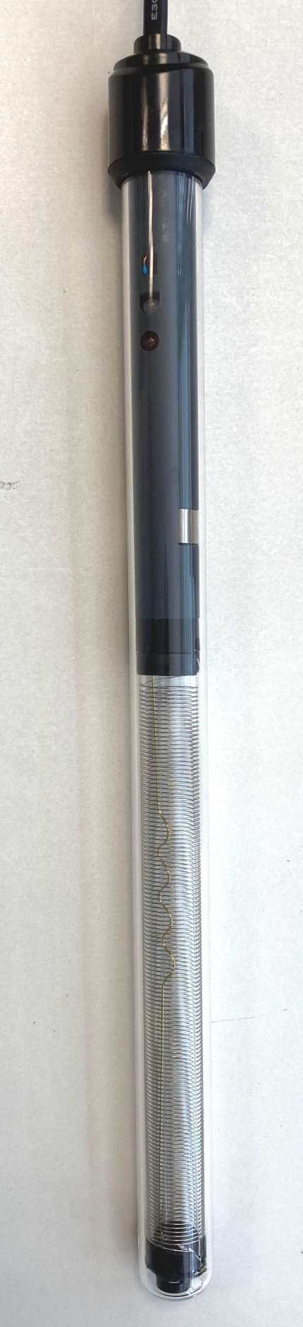
Click to zoom
Application Details
- Equipment Class
- JAB - Part 15 Class B Digital Device
- Date of Grant
- Jun 29, 2021
- Application Purpose
- Original Equipment
- Date of Application
- Jun 29, 2021
- Equipment Note
- Aquarium Heater
- Company
- Eheim GmbH&Co.KG
- Country
- Germany
Documents & Files
Document Text
Text extracted from the exhibit documents filed with the FCC. Open a document above to read the original.
Users Manual
en Operating manual fr Mode d'emploi es Manual de instrucciones AQUARIUM HEATER PRO150 W (Type 5310051) PRO200 W (Type 5310053) PRO300 W (Type 5310052) A min. water level B C Technical data Type HEATER TOPFIN Ø L Watt US gal 5310051150 Ø 1.26 × 12.87 inch150 W120 V / 60 Hzup to 79 5310053200 Ø 1.26 × 15.19 inch200 W120 V / 60 Hzup to 106 5310052300Ø 1.26 × 19.13 inch300 W120 V / 60 Hzup to 160 b c d e g f a USA 3 IMPORTANT SAFETY INSTRUCTIONS WARNING- To guard against injury, basic safety precautions should be observed, including the following. ‧FOR HOUSEHOLD USE ONLY ‧WARNING! RISK OF ELECTRIC SHOCK! ‧DO NOT RUN DRY! READ AND FOLLOW ALL SAFETY INSTRUCTIONS. ‧DANGER – To avoid possible electric shock, special care should be taken since water is employed in the use of aquarium equipment. For each of the following situations, do not attempt repairs by yourself. Return the appliance to an authorized service facility for service or discard the appliance. ‧If the appliance shows any sign of abnormal water leakage, immediately unplug it from the power source. ‧Carefully examine the appliance after installation. It should not be plugged in if there is water on parts not intended to be wet. ‧Unplug the appliance from the socket outlet to disable any remote command. ‧Do not operate any appliance if it has a damaged cord or plug, or if it is malfunctioning or has been dropped or damaged in any manner. ‧To avoid the possibility of the appliance plug or receptacle getting wet, position aquarium stand and tank to one side of a wall-mount - ed receptacle to prevent water from dripping onto the receptacle or plug. A ”drip loop”, shown in the figure, should be arranged by the user for each cord connecting an aquarium appliance to a receptacle. The ”drip loop” is that part of the cord below the level of the receptacle, or the connector if an extension cord is used, to prevent water traveling along the cord and coming in contact with the receptacle. If the plug or socket does get wet, DON’T unplug the cord. Disconnect the fuse or circuit breaker that supplies power to the appliance. Then unplug and examine for presence of water in the receptacle. ‧Close supervision is necessary when any appliance is used by or near children. ‧To avoid injury, do not touch moving parts or hot parts such as heaters, reflectors, lamp bulbs, and the like. ‧Always unplug an appliance from an outlet when not in use, before putting on or taking off parts, and before cleaning. Never yank cord to pull plug from outlet. Grasp the plug and pull to disconnect. ‧Do not use an appliance for anything other than its intended use. The use of attachments not recommended or sold by the appli - ance manufacturer may cause an unsafe condition. DRIP LOOP POWER SUPPLY CORD USA 4 ‧Do not install or store the appliance where it will be exposed to the weather or to temperatures below freezing. ‧Make sure an appliance mounted on a tank is securely in stalled before operating it. ‧Read and observe all the important notices on the appliance. ‧If an extension cord is necessary, a cord with a proper rating should be used. A cord rated for less amperes or watts than the appliance rating may overheat. Care should be taken to arrange the cord so that it will not be tripped over or pulled. ‧This appliance has a polarized plug (one blade is wider than the other). As a safety feature, this plug will fit in a polarized outlet only one way. If the plug does not fit fully in the outlet, reverse the plug. If still does not fit, contact a qualified electrician. Never use with an extension cord unless plug can be fully inserted. Do not attempt to defeat this feature. ‧Check that the voltage shown on the label of the unit corresponds to the voltage of the mains supply. ‧Disconnect all electrical appliances from the mains before placing hands in the water. ‧The line cord of this unit cannot be replaced or repaired. Should the line cord become damaged the appliance must be discarded. SAVE THESE INSTRUCTIONS FCC WARNING STATE- MENT (US only) FCC CAUTION ‧This device complies with part 15 of the FCC Rules. Operation is subject to the following two conditions: ‧(1) This device may not cause harmful interference, and (2) this device must accept any interference received, including interfer - ence that may cause undesired operation. ‧ Any changes or modifications not expressly approved by the party responsible for compliance could void the user’s authority to operate the equipment. ‧This equipment complies with FCC radiation exposure limits set forth for an uncontrolled environment. This equipment should be installed and operated with a minimum distance of 20 cm between the radiator and your body. NOTE: This equipment has been tested and found to comply with the limits for a Class B digital device, pursuant to Part 15 of the FCC Rules. These limits are designed to provide reasonable protection against harmful interference in a residential installation. This equipment generates, uses and can radiate radio frequency energy and, if not installed and used in accordance with the instructions, may cause harmful interfer- ence to radio communications. However, there is no guarantee that interference will not occur in a particular installation. If this equipment does cause harmful interference to radio or television reception, which can be determined by turning the equipment off and on, the user is encouraged to try to correct the interference by one or more of the following measures: ‧Reorient or relocate the receiving antenna. ‧Increase the separation between the equipment and receiver. USA 5 ‧ Connect the equipment into an outlet on a circuit different from that to which the receiver is connected. ‧Consult the dealer or an experienced radio/TV technician for help. English 6 Operating manual TOP FIN ® Pro Adjustable Aquarium Heater General User Instructions Follow all operating manual instructions ▶ Before using the appliance for the first time, the operating manual must be rea…
Text truncated - open the document above for the full version.
Users Manual
12 Wireless Connectivity Manual Contents 1. Symbols ........................................ 13 2. Initial configuration ........................ 14 3. HOME ..................................... 19 4. HEATER OVERVIEW ............. 21 5. Heater Mode ........................... 23 5.1 MANUAL CONTROL .......... 24 5.2 SMART CONTROL ............ 24 6. Settings Home ......................... 27 6.1 Connect With Available Network ................................... 29 6.2 E-Mail Adress for Heater Messages ................................ 31 6.3 Deactivating WLAN ................. 32 6.4 Activating WLAN ..................... 33 7. Heater Settings ........................ 33 8. Status LED indicator ..................... 36 9. Reset ............................................ 38 10. Connecting with other Topfin PRO® device ..................... 38 11. Information .................................... 40 13 1. Symbols Home page Settings Remove Change Save Add device Overview Manual control Smart Control Temperature / Current water temperature Heater heats Time Temperature setpoint Factory Defaults Attention 14 2. Initial Configuration 1 Select language 2 Select unit system 3 Change name of heater (optional) 4 Enter and save preferred name (optional). 15 5 Select next setting 6 Add a new aquarium to network 7 Change name (optional) 8 Select next setting. Continue with Step 12. 9 Connecting with an existing aquarium (optional). 16 10 Selecting an aquarium from the list. 11 Connecting the aquarium. 12 Select heater regulation type MANUAL CONTROL 13 Set the setpoint temperature by moving the slider 17 14 Save the settings. Continue with Step 24 15 Select heater regulation type SMART CONTROL 16 Search for other Topfin PRO ® devices. 17 Select your device. 18 18 Select your filter 19 Pair with device 20 To pairing this filter it must be configured in Bio Mode. 21 Set the setpoint temperature during the day Filter XXXXXXX EHEIM Filter_XXXXXXX Filter XXXXXXX 19 22 Set the temperature difference at night. 23 Save settings. 3. Home Page 24 HOME PAGE Overview of aquarium with all connected devices. Filter XXXXXXX Filter XXXXXXX 20 25 Change name 26 Enter and save preferred name. 27 Add a new aquarium. 28 Remove aquarium. 21 29 Add device. 30 Change to view the heater overview. 4. Heater Overview 31 Heater Overview: The current heater mode, temperature setpoint and current water temperature 32 Heater ON/OFF 22 33 Change the temperature setpoint. 34 Show the selection menu for OVERVIEW, TEMPERATURE and SETTINGS. 35 Go back to home page. 23 5. Heater Mode 36 HOME PAGE Select the heater overview. 37 Show the selection menu. 38 Select TEMPERATURE for heater modes 39 Overview of heater modes 24 5.1 MANUAL CONTROL 40 Select MANUAL CONTROL 41 Set the setpoint temperature by moving the slider 42 Save the settings. 5.2 SMART CONTROL 43 Select SMART CONTROL 25 44 Search for other Topfin PRO ® devices. 45 Select your device. 46 Select the network 47 Pair with device EHEIM Filter_XXXXXXX 26 48 To pairing this filter it must be configured in Bio Mode. 49 Set the setpoint temperature during the day 50 Set the temperaure difference at night. 51 Save settings. Filter XXXXXXX Filter XXXXXXX Filter XXXXXXX Filter XXXXXXX 27 6. Settings Home 52 Select settings 53 Call up network setting. Continue with 6.1. 54 Select/change language. 55 Enter the e-mail address and user name to receive messages from the heater. Continue with 6.2. 28 56 The current time is set. 57 Manual setting of date and time 58 Activate/deactivate automatic change between summer and winter time 59 Display network information and switching off the WiFi function 60 Reset to factory settings. 29 61 Carry out manual update. 6.1 Connect With Available Network 62 Search for available networks. 63 Connect available network. 64 Enter password for the selected network. 30 65 Select CONNECT to connect to the network. 66 Change Heater XXXXXXXX network name to your own name. 67 Activate password usage and use a password with a minimum of 8 characters. 68 Save network settings. Heater_XXXXXXXX Heater_XXXXXXXX #x1y2z3# 31 69 Go back to settings. 6.2 E-Mail Adress for Heater Messages 70 Enter the e-mail address and user name to receive messages from the heater. Only possible in networks with Internet connection. 71 Read and confirm the privacy policy. 72 Save the data. Fish.mä[email protected] Ronnald Mäc Donnald Ronnald Mäc Donnald Fish.mä[email protected] 32 6.3 Deactivating WLAN 73 Select “Show Network Information”. 74 Select “Turn off WiFi Feature”. 75 Select “Deactivate WiFi” to disable the WiFi function. 33 76 Select “Deactivate WiFi” to disable the WiFi function. The status LED light y on the heater flashes continuously yellow after approx. 3 - 5 seconds. WiFi function deactivated. Device settings remain available. 6.4 Activating WLAN 77 Press the red reset button u for approx. 3 – 5 seconds until the status LED lights up green. 78 The status LED flashes white. Network is being created. This process may take a few seconds. 79 If the status LED lights blue, a network has been created and is visible on a WLAN- enabled device (smart phone, tablet, etc.). 7. Heater Settings 80 Change to the heater overview. 34 81 Show the selection menu for OVERVIEW, TEMPERATURE and SETTINGS. 82 Select settings 83 Enter and save preferred name (see items 3 & 4). 84 Open heater expert settings 35 85 Adjustment of actual temperature with external thermometer. Example: Actual temperature = 79°F Display thermometer = 77°F Setting calibrate temperature = -2°F 86 Select ”Show Network Information“. 87 Change name. 88 Initial configuration reset. 36 89 Reset to factory settings. 8. Status LED indicator 90 LED flashes white: Device control unit is starting. 91 LED lights permanently blue: Device is ready for operation (MASTER) and can be connected to WLAN- capable device (smart phone, tablet, etc.). 92 LED lights permanently green: The device is ready for operation and is connected to a MASTER device. 93…
Text truncated - open the document above for the full version.
External Photos
EXTERNAL PHOTOS Page 1/2 7376960 EXTERNAL PHOTOS Page 2/2 7376960
ID Label/Location Info
EHEIM brand TOPFIN brand Page 1/1 7376960 100 mm 27 mm e Contains IC: 23236-ESP12F Contains FCC ID: 2AHMR-ESP12F FCC ID: 2AY5F-7376960 e e e e e e e Contains IC: 23236-ESP12F Contains FCC ID: 2AHMR-ESP12F FCC ID: 2AY5F-7376960 Contains IC: 23236-ESP12F Contains FCC ID: 2AHMR-ESP12F FCC ID: 2AY5F-7376960 Contains IC: 23236-ESP12F Contains FCC ID: 2AHMR-ESP12F FCC ID: 2AY5F-7376960 Contains IC: 23236-ESP12F Contains FCC ID: 2AHMR-ESP12F FCC ID: 2AY5F-7376960 Contains IC: 23236-ESP12F Contains FCC ID: 2AHMR-ESP12F FCC ID: 2AY5F-7376960 Contains IC: 23236-ESP12F Contains FCC ID: 2AHMR-ESP12F FCC ID: 2AY5F-7376960 Contains IC: 23236-ESP12F Contains FCC ID: 2AHMR-ESP12F FCC ID: 2AY5F-7376960 LABELS
ID Label/Location Info
LABELS POSITION The space available on data plate label do not allow to write all the required full compliance statement. Only the FCC ID number is provided on the appliance. The full statement, as per Section 15.19(a), has been placed in the user manual. Data Plate Label EHEIM brand TOPFIN brand Page 1/1 7376960
Test Report
UL INTERNATIONAL GERMANY GMBH Hedelfinger Str. 61 70327 Stuttgart, Germany [email protected] TEST REPORT Test Report No.: UL-RPT-EMC-13729908-116-FCC Applicant : EHEIM GmbH & Co. KG Model Number : 3669090 (5310052) FCC ID : 2AY5F-7376960 Technology : WLAN 2.4 GHz (802.11 b, g, n) Test Standard(s) : FCC Part 15.107 & 15.109 1. This test report shall not be reproduced in full or partial, without the written approval of UL International Germany GmbH. 2. The results in this report apply only to the sample tested. 3. The test results in this report are traceable to the national or international standards. 4. Test Report Version 1.1; supersedes Test Report Version 1.0 5. Result of the tested sample: PASS 6. For details of applied tests and test results refer to test results summary _________________________ _________________________ Prepared by: M. Asim Shahzad Approved by: Bernd Woerl Title: Engineer Title: Operations leader Date: 07.06.2021 Date: 16.06.2021 This laboratory is accredited by DAkkS. The tests reported herein have been performed in accordance with its’ terms of accreditation. UL INTERNATIONAL GERMANY GMBH TEST REPORT NO: UL-RPT-RP-13729908-116-FCC TEST REPORT VERSION 1.1 ISSUE DATE: 16.06.2021 Page 2 of 21 FCC Test Report Template Version 2.7 This page has been left intentionally blank. UL INTERNATIONAL GERMANY GMBH TEST REPORT NO: UL-RPT-RP-13729908-116-FCC TEST REPORT VERSION 1.1 ISSUE DATE: 16.06.2021 Page 3 of 21 FCC Test Report Template Version 2.7 Table of Contents 1. Customer Information ........................................................................................................ 4 1.1. Applicant information 4 1.2. Manufacturer Information 4 2. Summary of Testing ........................................................................................................... 5 2.1. General Information 5 2.2. Summary of Test Results 6 2.3. Method and procedure 6 2.4. Deviations from the Test Specification 6 Equipment Under Test (EUT) ............................................................................................. 7 Identification of Equipment under Test (EUT) 7 Description of Equipment Under Test (EUT) 7 Modifications Incorporated in the EUT 7 Operating Modes 7 Additional Information Related to Testing 7 Support Equipment 8 A. Support Equipment (In-house) 8 B. Support Equipment (Manufacturer supplied) 8 C. Interconnecting cables and Ports (Manufacturer/Applicant supplied) 8 Operation and Monitoring of the EUT during Testing ...................................................... 9 Operating Modes 9 Configuration and Peripherals 9 Measurement Uncertainty .................................................................................................10 Overview 10 Test Results .......................................................................................................................11 AC Conducted Emission 11 6.1.1 Test Summary: 11 6.1.2 Test Setup: 11 6.1.3 Numerical Results: 12 6.1.4 Graphical Plots: 13 Radiated Emissions below 1GHz 14 6.2.1 Test Summary: 14 6.2.2 Test Setup: 14 6.2.3 Numerical Results: 15 6.2.4 Graphical Plots: 16 Radiated Emissions above 1GHz/ Radiated Emissions from 1GHz to 18GHz 17 6.3.1 Test Summary: 17 6.3.2 Test Setup: 17 6.3.3 Numerical Results: 18 6.3.4 Graphical Plots: 19 Used equipment ................................................................................................................20 Report Revision History ....................................................................................................21 UL INTERNATIONAL GERMANY GMBH TEST REPORT NO: UL-RPT-RP-13729908-116-FCC TEST REPORT VERSION 1.1 ISSUE DATE: 16.06.2021 Page 4 of 21 FCC Test Report Template Version 2.7 1. Customer Information 1.1. Applicant information Company Name: EHEIM GmbH & Co. KG Company Address: Plochinger Strasse 54; 73779 Deizisau; Germany Contact Person: Mr. Jan Winnacker Contact E-Mail Address: [email protected] Contact Phone No.: +49 7153 7002 240 1.2. Manufacturer Information Company Name: EHEIM GmbH & Co. KG Company Address: Plochinger Strasse 54; 73779 Deizisau; Germany Contact Person: Mr. Jan Winnacker Contact E-Mail Address: [email protected] Contact Phone No.: +49 7153 7002 240 UL INTERNATIONAL GERMANY GMBH TEST REPORT NO: UL-RPT-RP-13729908-116-FCC TEST REPORT VERSION 1.1 ISSUE DATE: 16.06.2021 Page 5 of 21 FCC Test Report Template Version 2.7 2. Summary of Testing 2.1. General Information Applied Standards Specification Reference: 47CFR15.107 and 47CFR15.109 Specification Title: Code of Federal Regulations Volume 47 (Telecommunications): Part 15 Subpart B (Unintentional Radiators) – Sections 15.107 and 15.109 Test Firm Registration: 399704 Location Location of Testing: UL International Germany GmbH Hedelfinger Str. 61 70327 Stuttgart Germany Date information Order Date: 08.03.2021 EUT arrived: 11.05.2021 Test Dates: 20.05.2021 & 22.05.2021 EUT returned: -/- UL INTERNATIONAL GERMANY GMBH TEST REPORT NO: UL-RPT-RP-13729908-116-FCC TEST REPORT VERSION 1.1 ISSUE DATE: 16.06.2021 Page 6 of 21 FCC Test Report Template Version 2.7 2.2. Summary of Test Results Clause Measurement Complied Did not complied Not performed Not applicable Part 15.107 (a) AC Conducted Emissions ☒ ☐ ☐ ☐ Part 15.109 (a) Radiated Emissions ☒ ☐ ☐ ☐ Decision rule: Where not otherwise specified or communicated in writing, statements of conformity (e.g. Pass/Fail) are established according to the following decision rule: considering that the applied test standards take measurement uncertainty into account, acceptance limit equals the tolerance limit (Accuracy Method). This leads to a maximum 50% of false accept or false reject when the measured value equals the tolerance limit. See ILAC-G8:09/2019 for further details. Note: Complies with class B limits. Information regarding class A and class B devices Excerpt of Title 47 chapter I Part 15 subchapter A § 15.3 Definitions (h) Class A digital device. A digital device that is marketed f…
Text truncated - open the document above for the full version.
Test Setup Photos
EHEIM GmbH & Co. KG FCC ID: 2AY5F-7376960 UL-RPT-13729908-116 ISED ID: not stated UL International Germany GmbH Page 1 of 3 Test Setup Photographs for the 3669090 (5310052) 1. Conducted Emissions Photo 1: Conducted Test Setup from 150 kHz to 30 MHz Photo 2: Conducted Test Setup from 150 kHz to 30 MHz EHEIM GmbH & Co. KG FCC ID: 2AY5F-7376960 UL-RPT-13729908-116 ISED ID: not stated UL International Germany GmbH Page 2 of 3 2. Radiated Emissions Photo 3: Radiated Test Setup from 30 MHz to 1 GHz Photo 4: Radiated Test Setup from 30 MHz to 1 GHz EHEIM GmbH & Co. KG FCC ID: 2AY5F-7376960 UL-RPT-13729908-116 ISED ID: not stated UL International Germany GmbH Page 3 of 3 Photo 5: Radiated Test Setup from 1 GHz to 18 GHz Photo 6: Radiated Test Setup from 1 GHz to 18 GHz
Contact Information
Applicant
Jan Winnacker
Technical Contact
EHEIM GmbH & Co. KGJan - Winnacker
[email protected]+49 071537002
Plochinger Str 54 · Deizisau · Germany
Test Firm
UL International Germany GmbHBernd Woerl
Technical Specifications
| # | Rule Parts | Frequency Range | Power Output |
|---|---|---|---|
| 1 | 15B | - | - |