2AYB3-HD06VCRHSensor
SHENZHEN BETOP ELECTRONICS CO LTD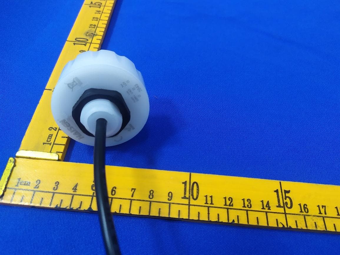
Click to zoom
Application Details
- Equipment Class
- DXX - Part 15 Low Power Communication Device Transmitter
- Date of Grant
- Dec 20, 2020
- Application Purpose
- Original Equipment
- Date of Application
- Dec 16, 2020
- Equipment Note
- Sensor
- Frequency Range
- 5750.00000000 - 5824.00000000
- Country
- China
Documents & Files
Document Text
Text extracted from the exhibit documents filed with the FCC. Open a document above to read the original.
Users Manual
This figure indicates the maximum distance at the highest mounting height with 100% sensitivity. Detection coverage Typical installation height 15m HD06VCRH Haisen Technology | 01Specifications subject to change without notice.©All rights reserved. Technical data Dimensions (Unit: mm) 1. Automatic On/off control with Daylight sensor. 2. Optional detection range, holdtime , daylight threshold, Stand-by period and Stand-by dimming level. 3. Remote control setting. 4. 5 year limited warranty. 15m 10-15M Highbay altitude Daylight threshold Stand-by period Stand-by dimming level Hold time Detection area On/off control Remote control setting 5 years 2345623456 Ceiling Mounted 2 4 6 8 10 12 14 16 Mounting height Wall Mounted 24681018161412 1 2 3 4 1 2 3 4 CoveredWell covered Mounting height Detection area DIM 0-10V 0s/10s/30s/1min/5min/10min/30min/+∞ 10%/20%/30%/50% Max,ø14m/45.92ft (ceiling mounted) 15m/49.2ft (ceiling mounted) Operating voltage Operating current Output ≤0.5WStand-by power Hold time Daylight threshold Stand-by period Stand-by dimming level 5750-5824MHz <0.3mW Microwave frequency Microwave power Mounting height Detection range 0.5~1.5m/s Operating temperature IP rating 12VDC 30mA±5% IP65 Motion detection -20°C~+60°C Warranty5 years 2Lux/10Lux/30Lux/50Lux/80Lux/120Lux/Disable 25%/50%/75%/100% 5s/30s/1min/3min/5min/10min/20min/30min LED D rive r Red: 12V Grey: GND Purple: DIM DIM GND 12V ø50 50 24 12 22.5 Wiring diagram Sensor Piug & Play Haisen Technology | 02 Shenzhen Haisen Technology Co., Ltd., Tel: +86-755-82598105 Fax: +86-755-82598106Email: [email protected] www.haisensz.com Light off when ambient lux level is higher than preset lux amount. Light automatically on when ambient brightness is lower than preset lux level. With insufficient ambient brightness, light dims to 100% when motion detected . Light dims to standby level if no motion detected after holdtime. Application____Daylight priority Daylight Priority + Base Sensor Module Empty Cover Motion sensor Motion sensor No sensor No sensor + The bottom part will be always on the lighting fixtures; if the function is needed, the module will be placed inside; if no function needed, the module will be removed. It doesn't hurt the looking of the whole pack. Icon No icon The cover with humanoid icon indicates there is built-in microwave module with sensor function; The cover without humanoid icon indicates there is no built-in module as well as sensor function. Natural light Lux off Lux on light on automatically light off automatically Precondition of Daylight priority: 1. Standby period is +∞; 2. Standby dimming level is on 10%, 20% or 30%; 3. Daylight threshold is on 30Lux, 50Lux, 80Lux or 120Lux. With Daylight priority function, HD06VCRH 3 is able to differentiate artificial light brightness from natural light after installed inside the fixture, and automatically turn off light when ambient brightness exceeds preset lux level. Dusk/Dawn sensor: Dual-PD technology brings a fully automatic dusk/dawn sensor which can tell the difference between natural light and LED light, to ensure the light will be off when needed. Haisen Technology | 03 Shenzhen Haisen Technology Co., Ltd., Tel: +86-755-82598105 Fax: +86-755-82598106Email: [email protected] www.haisensz.com Installation Method With insufficient daylight, when motion detected, light ON. With sufficient daylight, even when motion detected, light remains OFF. After the stand-by period, light OFF. After last detection, the light will be dimmed down to the stand-by dimming level (10%,20%,30% or 50%) after holdtime. Hold time Stand-by period 3. Function Demo - Dimmable control/Corridor function Hold time After the last detection and the present hold time elapsed, light OFF. With sufficient daylight, even when motion detected, light remains OFF. With insufficient daylight, when motion detected, light ON. After people leave the detection area, light remains 100% brightness within hold time. When motion is detected, the sensor will switch on the light to 100% brighteness. After the last detection and the present hold time elapsed, light OFF. 1. Automatically ON/OFF function: Light on when detect movement and off after people leave at night. Applications: Corridor, Staircase. 1 2 1 2 3 2. No daylight function The daylight threshold is set to "Disable". Light on when detect movement, After people leave, Light off after stand-by period. Applications: Dim places such as Basement Parking, Underpass. HD05R Remote Control Applications The button “Test (2s)” is for testing purpose after commissioning.Pressing this button, the sensor goes to test mode (hold time is only 2s ). Detection Rarea Daylight Threshold Stand-by dimming level Definition of the ambient brightness; only when the ambient brightness is lower than the preset specific lux amount, the sensor will work; when it's preset as "disable", the sensor works everytime it detects motion regardless of the ambient lux level. - + Increase or decrease the parameters. Test (2s) Scene WM/PIR Hold time Stand-by period Press “Reset” button, products with DIP switch will be controlled by DIP switches; otherwise all the setting will be just initial, that is 100% detection range,hold time 5S, no stand-by time and daylight threshold disabled. The period of light keeping low output before it gets completely off. When it's preset as --, the light always keep at low output even no movement in the detection area. Turn on or turn off the remote control. ON/OFF Start Memory Apply Press the button before choosing the parameters. Press the button after choosing all the parameters to save them. Press the button to deliver the saved settings to the other sensors directly. Press the button to change the output power from 0% to 100%, it changes 5% every press. Power % Change from the microwave sensor function to PIR sensor function, and the other around. The area in which movement will trigger the sensor, 100% detection area also means strong sensitivity. Th…
Text truncated - open the document above for the full version.
Cover Letter(s)
DATE : 2020.12.04 Federal Communications Commission Authorization & Evaluation Division 7345 Oakland Mills Road Columbia, Maryland 21046 RE: LETTER OF AGENT AUTHORIZATION To Whom It May Concern: We, the undersigned, hereby authorize Compliance Testing, LLC to act on our behalf in all matters relating to application for equipment authorization, including the signing of all documents relating to these matters. We also hereby certify that no party to the application authorized hereunder is subject to the denial of benefits, including FCC benefits, pursuant to Section 5301 of the Anti-Drug Abuse Act of 1988, 21 U.S.C.853(a). Sincerely, <Signature> Name: Rock Huang Title: Manager Applicant Company: Dongguan New Testing Centre Co., Ltd
External Photos
External photos Model No: HD06VCRH
ID Label/Location Info
Label and label location Model No: HD06VCRH
Internal Photos
Internal Photos Model No: HD06VCRH Antenna
Test Report
Dongguan New Testing Centre Co., Ltd E-mail: [email protected] 3F, No. 1 the 1st North Industry Road, Songshan Lake Science & Technology Park, Dongguan, Guangdong, China, 523808 Page 1 of 27 Report No.:NTC-ER2011043 FCC TEST REPORT Report No. ...................................... : NTC-ER2011043 Applicant’s name ........................... : SHENZHEN BETOP ELECTRONICS CO LTD Address ............................................ : Room B0924,No.2 Building,No.8 Skyworth Innovation Valley,1st Tangtou Road, Shiyan Town, Baoan Dist., Shenzhen, Guangdong , China. 518108 Dongguan New Testing Centre Co., Ltd E-mail: [email protected] 3F, No. 1 the 1st North Industry Road, Songshan Lake Science & Technology Park, Dongguan, Guangdong, China, 523808 Page 1 of 27 Report No.:NTC-ER2011043 TABLE OF CONTENTS Test Report Declare ...................................................................................................................... 3 1. Summary of test results ........................................................................................................... 3 2. General test information .......................................................................................................... 3 2.1. Description of EUT ................................................................................................................... 3 2.2. Support Equipment ................................................................................................................... 4 2.3. Block diagram EUT configuration for test ............................................................................. 4 2.4. Test environment conditions ................................................................................................... 4 2.5. Measurement uncertainty ........................................................................................................ 4 3. Power Line Conducted Emission Test .................................................................................. 5 3.1. Test equipment ......................................................................................................................... 5 3.2. Block diagram of test setup ..................................................................................................... 5 3.3. Power Line Conducted Emission Limits (Class B) .............................................................. 5 3.4. Test Procedure .......................................................................................................................... 6 3.5. Test Result ................................................................................................................................. 6 4. Radiated emission test ............................................................................................................. 9 4.1. Test equipment ......................................................................................................................... 9 4.2. Block diagram of test setup ................................................................................................... 10 4.3. Limit .......................................................................................................................................... 12 4.4. Test Procedure ........................................................................................................................ 13 4.5. Test result ................................................................................................................................ 13 5. -20dB Bandwidth .................................................................................................................... 19 5.1. Test equipment ....................................................................................................................... 19 5.2. Block diagram of test setup ................................................................................................... 19 5.3. Limit .......................................................................................................................................... 19 5.4. Test Procedure ........................................................................................................................ 19 5.5. Test result ................................................................................................................................ 20 6. Test setup photograph ........................................................................................................... 22 6.1. Photos of power line conducted emission test .................................................................. 22 6.2. Photos of radiated emission test.......................................................................................... 22 7. Photos of the EUT .................................................................................................................. 24 Dongguan New Testing Centre Co., Ltd E-mail: [email protected] 3F, No. 1 the 1st North Industry Road, Songshan Lake Science & Technology Park, Dongguan, Guangdong, China, 523808 Page 2 of 27 Report No.: NTC-ER2011043 TEST REPORT DECLARE Test Standard Used: FCC Rules and Regulations Part 15 Subpart C: 2017, ANSI C63.10:2013. We Declare: The equipment described above is tested by Dongguan New Testing Centre Co., Ltd and in the configuration tested the equipment complied with the standards specified above. The test results are contained in this test report and Dongguan New Testing Centre Co., Ltd is assumed of full responsibility for the accuracy and completeness of these tests. After test and evaluation, our opinion is that the equipment provided for test compliance with the requirement of the above FCC standards. Report No.: NTC-ER2011043 Date of Test: Nov.16, 2020 to Nov.27, 2020 Date of Report: Nov.30, 2020 Prepared By: Approved By: ________________ _____________________ Jeffery Zhang/Engineer Dave Gou/LAB Manager Not…
Text truncated - open the document above for the full version.
Test Setup Photos
Setup photos Model No: HD06VCRH Conducted emission test Radiated emission test 30MHz – 1GHz Above 1GHz
Contact Information
Applicant
huifeng Zhou(Manager)
Test Firm
Dongguan New Testing Centre Co., LtdDave Gao
[email protected]86-15625558400
Technical Specifications
| # | Rule Parts | Frequency Range | Power Output |
|---|---|---|---|
| 1 | 15C | 5.75 GHz - 5.82 GHz | - |