2AYCYMA-C5LED Matter Controller
ZHUHAI LTECH TECHNOLOGY CO., LTD.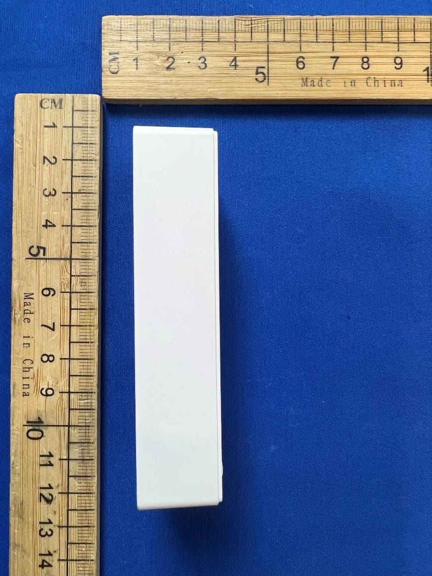
Click to zoom
Application Details
- Equipment Class
- DTS - Digital Transmission System
- Date of Grant
- Feb 24, 2026
- Application Purpose
- Original Equipment
- Equipment Note
- LED Matter Controller
- Frequency Range
- 2405.00000000 - 2480.00000000
- Country
- China
Documents & Files
Document Text
Text extracted from the exhibit documents filed with the FCC. Open a document above to read the original.
Users Manual
Technical Specifications Unit:mm Dimension Drawing 91 37 21 DIM/CT/RGBCW Matter LED Controller Matter Matter over Thread certified devices require pairing with a Matter hub featuring Thread border router functionality; Supports control via major smart home platforms including Apple Home, Google Home, Amazon Alexa, SmartThings, etc.; Supports voice control via Apple Siri, Google Assistant, Amazon Alexa, Samsung Bixby, etc.; Can be networked by scanning a QR code or via NFC one-touch pairing without scanning; Supports Matter standard OTA updates; Features NFC quick programming, allowing adjustment of on/off fade times, brightness ranges, and other parameters via smartphone app using NFC; ( NFC technology is only for receiving.) Compact and lightweight design with housing made from Covestro/ Samsung V0-rated flame-retardant PC material; Includes soft-start gradual brightening for enhanced visual comfort; IP20 protection rating. MA-C1, MA-C2, MA-C3, MA-C4, MA-C5 Input Signal Protection Type Model MA-C5 I nput Voltage O u tput Voltage Working Temperature Load Power Channels Product Dimensions 5CH Package Dimensions Weight (Gross Weight) Matter over Thread L 91×W37×H21(mm) L94×W39×H22(mm) 46g Short-circuit, over-temperature, over-current protection, reverse polarity protection MA-C1 -25°C ~ 50°C 12-48V 12-48V 1CH MA-C2 2CH 120W@12V 240W@24V 360W@36V 480W@48V 120W@12V 240W@24V 324W@36V 432W@48V 180W@12V 360W@24V 540W@36V 720W@48V Push Dim No YesYes Load Current Service Life 1 00000 Hours RGB Max.15A 5A/CH CW Max.10A 10A@12V 10A@24V 10A@36V 10A@48V 10A/CH@12V 10A/CH@24V 9A/CH@36V 9A/CH@48V Supported Platform Apple Home, Google Home, Amazon Alexa, Amazon Alexa, SmartThings All smart home platforms supporting the standard Matter protocol. Connection Diagram power supply 12-48Vdc PUSH DIM + - DIM Single tap: On/Off Long press: DIM ± Double tap: No action + - MA-C1 + WW CW CT + WW CW Single tap: On/Off Long press: DIM ± / CT ± Double tap: Switch modes (DIM / CT) MA-C2 CT MA-C2 WW CW (Two-Wire Wiring Method) + R G B WW CW RGBCW MA-C5 APP Router M atter Hub (With Thread Router Capability) DIM/CT/RGBCW Matter LED Controller Press and hold the reset button for 6 seconds. The light will flash 5 times, indicating that the controller has been restored to its factory settings. Reset button APP APP Router R outer Matter Hub (With Thread Router Capability) Matter Hub (With Thread Router Capability) APP Router M atter Hub (With Thread Router Capability) power supply 12 -48Vdc power supply 12-48Vdc power supply 12-48Vdc Press and hold the reset button for 6 seconds. The light will flash 5 times, indicating that the controller has been restored to its factory settings. Reset button Press and hold the reset button for 6 seconds. The light will flash 5 times, indicating that the controller has been restored to its factory settings. Reset button Press and hold the reset button for 6 seconds. The light will flash 5 times, indicating that the controller has been restored to its factory settings. Reset button PUSH DIM PUSH DIM Single tap: On/Off Long press: DIM ± / CT ± Double tap: Switch modes (DIM / CT) Matter MA-C1, MA-C2, MA-C3, MA-C4, MA-C5 DIM/CT/RGBCW Matter LED Controller Installation Precautions ≥15cm ≥ 15cm ≥ 15cm ≥ 15cm ≥ 15cm ≥ 100cm Please do not stack the products. The distance between two products should be ≥15cm so as not to affect heat dissipation and the lifespan of the products. Please do not place the products on the floor. The distance between the product and the floor should be ≥100cm so as to avoid signal interference. Please do not place the products near a large area of metal objects (such as metal stud ceilings). The distance between the product and the metal object should be ≥15cm so as to avoid signal interference. Please do not install the products on beams or near the corners. The distance between the product and the beam or the corner should be ≥15cm so as to avoid signal interference. Woodiness GasketGasket Woodiness Do not x the product screws tightly against the wooden board. Instead, add a washer with a thickness of ≥ 7mm under the xing screws. Leaving some gaps can eectively dissipate heat, preventing any impact on the product's heat dissipation performance and service life. Add to Matter Platform Instructions 1. This device supports control via major smart home platforms, including Apple Home, Amazon Alexa, Google Home, SmartThings, and others. 2. To connect Matter over Thread devices, you need a Matter hub supporting Thread border router func tionality from major platforms. Refer to the image below for compatible models. 3. This guide uses Apple Home as an example. First, prepare an iPhone (iOS 16.2 or later) or iPad (i PadOS 16.2 or later) with the latest firmware, along with an Apple HomePod mini also running the latest firmware. Then connect your iPhone or iPad to your home Wi-Fi network, launch the Apple Home app, and follow Apple's instructions to set up the HomePod mini. For iPhone models 16 and above, no Matter hub is required; devices can be added directly. * Amazon AlexaApple Home Google HomeSmartThings Amazon Echo (4th-gen) Amazon Echo Hub Amazon Echo Show 8 (3rd-gen) Amazon Eero 6, Pro 6, 6 Plus, Max 7 etc. Apple HomePod (second-gen) Google Nest Hub (2nd Gen) Aeotec SmartThings Smart Home Hub Apple HomePod Mini Google Nest Hub Max Apple TV 4K (2nd gen) Google Nest Wifi Pro Samsung SmartThings Hub Dongle Apple TV 4K (3rd gen,128 GB) Google TV Streamer (4K) Samsung SmartThings Hub v3 Samsung SmartThings Station Matter MA-C1, MA-C2, MA-C3, MA-C4, MA-C5 ControllerAPP DIM/CT/RGBCW Matter LED Controller Matter System Diagram Router M atter Hub (with Thread routing capability) 1. Add accessories Open the Apple Home app and tap “Add or Scan Accessories.” Add the device to the Home app by scanning the QR code sticker on the device, as shown below. *Alternatively, you can add it via NFC: Open the Home app and hold it near the device's NFC sensor area to add it. Add Steps Matte…
Text truncated - open the document above for the full version.
Attestation Statements
* the applicantmust designatea contactlocatedin the UnitedStatesfor purposesof actingas the applicant’s agent for serviceof process,regardlessof whetherthe applicantis a domesticor foreign entity.An applicantlocatedin the UnitedStatesmay designateitself as the agent for serviceof process. SC6010077 U.S. AgentDesignationfor Serviceof Process- CertificationAttestationLetter 12/18/2025 TO : FederalCommunicationsCommission 7435 OaklandMills Road Columbia,MD 21046 ATTN.:ReviewingEngineer FCC ID: 2AYCYMA-C5 FRN of applicant:0030252274 Per section2.911(d)(7)of the FCC rules, ZHUHAILTECHTECHNOLOGYCO., LTD. FRN:0030252274(“the applicant”) certifiesthat the equipmentfor which authorizationis sought is designatedto thefollowingU.S.agent*forserviceof process: CompanyName:GlobalProductServicesand ConsultationLLC FCC RegistrationNumber(FRN):0033406703 PhysicalU.S. CompanyAddress:328 W Palm Ave. Monrovia,CA91016 ContactPerson:MichaelChan Tel: +1 626 366 4358 AgentEmail Address:[email protected] The abovecontactpersonacceptsthe obligationfor serviceof process. The applicantacceptsto maintainan agent for no less than one year after the granteehas terminatedall marketingand importationor the conclusionof any Commission-related proceedinginvolvingthe equipment. ApplicantSigned:AgentSigned(if differentfromApplicant): Signed: Printedname:XiaoyuWen Title: Manager CompanyName:ZHUHAILTECH TECHNOLOGYCO., LTD. Address:1st Building,No. 183, Shui'an1st Road, XiangzhouDistrict,519060ZhuhaiCity, Signed: Printedname:MichaelChan Title: TechnicalDirector CompanyName:GlobalProductServicesand ConsultationLLC Date: 2/4/2026 PEOPLE'SREPUBLICOF CHINA Date: 12/18/2025
Attestation Statements
ZHUHAI LTECH TECHNOLOGY CO., LTD. 2025-12-04 Eurofins Electrical and Electronic Testing NA, Inc. 914 West Patapsco Avenue Baltimore, MD 21230 RE: Attestation Statements Part 2.911(d)(5)(i) request for (FCC ID: 2AYCYMA-C5) [ZHUHAI LTECH TECHNOLOGY CO., LTD.] (“the applicant”) certifies that the equipment for which authorization is sought is not “covered” equipment prohibited from receiving an equipment authorization pursuant to section 2.903 of the FCC rules. We also certify that, as of the date of the filing of the application, the equipment does not utilize cyber-security or anti-virus software from Kaspersky Lab, Inc, or any of its successors and assignees, which is also on the “covered list”. Sincerely, Xiaoyu Wen Manager ZHUHAI LTECH TECHNOLOGY CO., LTD. 1st Building, No. 183, Shui'an 1st Road, Xiangzhou District, 519060 Zhuhai City, PEOPLE'S REPUBLIC OF CHINA ZHUHAI LTECH TECHNOLOGY CO., LTD. 2025-12-04 Eurofins Electrical and Electronic Testing NA, Inc. 914 West Patapsco Avenue Baltimore, MD 21230 RE: Attestation Statements Part 2.911(d)(5)(ii) request for (FCC ID: 2AYCYMA-C5) [ZHUHAI LTECH TECHNOLOGY CO., LTD.] (“the applicant”) certifies that, as of the date of the filing of the application, the applicant is not identified on the Covered List as an entity producing “covered” equipment. Sincerely, Xiaoyu Wen Manager ZHUHAI LTECH TECHNOLOGY CO., LTD. 1st Building, No. 183, Shui'an 1st Road, Xiangzhou District, 519060 Zhuhai City, PEOPLE'S REPUBLIC OF CHINA
Cover Letter(s)
ZHUHAI L TECH TECHNOLOGY CO., LTD. Declaration on model difference We the undersigned hereby confirm that these models are identical, and all models have the same RF module and antenna, PCB layout, schematics and component. Only the models name are different. Product name FCCID Model no. LED Matter Controller 2AYCYMA-CS MA-C1, MA-C2, MA-C3, MA-C4, MA-C5 Sincerely, Xiaoyu Wen Manager 心 沪 W 砍 ZHU HAI L TECH TECHNOLOGY CO., LTD. 产 一 《 心 总 1st Building, No. 183, Shui'an 1st Road, Xiangzhou District, 519060 Zhuhai City, PEOPLE'S REPUBLIC OF CHINA
Cover Letter(s)
ZHUHAI LTECH TECHNOLOGY CO., LTD. 2025-12-04 Eurofins Electrical and Electronic Testing NA, Inc. 914 We st Patapsco Avenue Baltimore, MD 21230 RE: CONFIDENTIALITY REQUEST FOR (EUT Name: LED Matter Controller / Model: MA-Cl, MA-C2, MA-C3, MA-C4, MA-CS /FCC ID: 2AYCYMA-C5) To Whom It May Concern: This letter serves as an official request for confidentiality under sections 0.457 and 0.459 of CFR 47. We have requested that the fBlock Diagram, Ope「ational Description, Schematicsl required to be submitted with this application be permanently withheld from public review. T he above materials contain trade sec「ets and proprietary info「mation not customa甘ly 「eleased to the public. The public disclosure of these materials may be ha「mful to the applicant and p「ovide unjustified benefits to its competito「S Please contact me if there is any information you may need. Sincere l y , Xiaoyu Wen Manager 卢C>A]\,(心 动达,心,心 ZHU HAI L TECH TECHNOLOGY CO., LTD. 1st Building, No. 183, Shui'an 1st Road, Xiangzhou District, 519060 Zhuhai City, PEOPLE'S REPUBLIC OF CHINA
External Photos
External
Internal Photos
Internal NFC Receiving Antenna Antenna
RF Exposure Info
RF EXPOSURE EVALUATION According to FCC 1.1310: The criteria listed in the following table shall be used to evaluate the environment impact of human exposure to radio frequency(RF) Radiation as specified in §1.1307(b) FCC ID: 2AYCYMA-C5 EUT Specification EUT LED Matter Controller Frequency band (Operating) BT: 2.402GHz ~ 2.480GHz Matter: 2.405GHz ~ 2.480GHz WIFI: 2.412GHz ~ 2.462GHz WIFI: 5.180GHz ~ 5.240GHz WIFI: 5.260GHz ~ 5.320GHz WIFI: 5.500GHz ~ 5.700GHz WIFI: 5.745GHz ~ 5.825GHz Device category Portable (<20cm separation) Mobile (>20cm separation) Exposure classification Occupational/Controlled exposure (S = 5mW/cm 2 ) General Population/Uncontrolled exposure (S=1mW/cm 2 ) Antenna diversity Single antenna Multiple antennas Tx diversity Rx diversity Tx/Rx diversity Max. output power -0.03dBm(0.9931mW) Antenna gain (Max) 5.3 dBi Evaluation applied MPE Evaluation SAR Evaluation 2 / 3 Limits for Maximum Permissible Exposure(MPE) Frequency Range(MHz) Electric Field Strength(V/m) Magnetic Field Strength(A/m) Power Density(mW/cm 2 ) Average Time (A) Limits for Occupational/Control Exposures 300-1500 -- -- F/300 6 1500-100000 -- -- 5 6 (B) Limits for General Population/Uncontrol Exposures 300-1500 -- -- F/1500 6 1500-100000 -- -- 1 30 Friis transmission formula: Pd=(Pout*G)\(4*pi*R2) Where P d = Power density in mW/cm 2 , P out =output power to antenna in mW. G= gain of antenna in linear scale, Pi=3.1416 R= distance between observation point and center of the radiator in cm=20cm P d the limit of MPE, 1mW/cm 2 . If we know the maximum gain of the antenna and total power input to the antenna, through the calculation, we will know the distance where the MPE limit is reached. For multiple RF sources: Multiple RF sources are exempt if: in the case of fixed RF sources operating in the same time-averaging period, or of multiple mobile or portable RF sources within a device operating in the same time averaging period, if the sum of the fractional contributions to the applicable thresholds is less than or equal to 1 as indicated in the following equation Evaluated k : the maximum reported SAR or MPE of fixed, mobile, or portable RF source k either in the device or at the transmitter site from an existing evaluation at the location of exposure. Exposure Limit k : either the general population/uncontrolled maximum permissible exposure (MPE) or specific Absorption rate (SAR) limit for each fixed, mobile, or portable RF source k. 3 / 3 Measurement Result Mode Max Measured Power (dBm) Tune up tolerance (dBm) Max tune up conducted power(dBm) Output Peak power (mW) Ant. Gain (dBi) Ant. Gain (numeric) Power density at 20cm (mW/ cm 2 ) Power density Limits (mW/ cm 2 ) Results Matter -0.03 0±1 1 1.2589 5.3 3.3884 0.000849 1 PASS Signature: Shawn Wen Date: 2025-12-2
Test Report
Application Note AN043 Small Size 2.4 GHz PCB antenna By Audun Andersen 1 KEYWORDS • CC25xx • CC24xx • CC2480 • PCB antenna • USB dongle • 2.4 GHz • Inverted F Antenna 2 INTRODUCTION The PCB antenna used on the CC2511 USB dongle reference design is described in this application note. Even if the antenna presented is for a USB dongle design it can be used in all 2.4 GHz designs, especially where small space is required for the antenna. This application note describes the antenna dimensions, the RF performance and considerations for complying with regulatory limits when using this design. The suggested antenna design requires no more than 15.2 x 5.7 mm of space and ensures a VSWR ratio of less than 2 across the 2.4 GHz ISM band when connected to a 50 ohm source. Figure 1: CC2511 USB Dongle SWRA117D Page 1 of 21 Application Note AN043 Table of Contents 1 KEYWORDS...................................................................................................................1 2 INTRODUCTION.............................................................................................................1 3 ABBREVIATIONS...........................................................................................................2 4 ANTENNA DESIGN........................................................................................................3 4.1 DESIGN GOALS..........................................................................................................3 4.2 SIMULATION...............................................................................................................3 4.3 LAYOUT AND IMPLEMENTATION...................................................................................4 5 TEST RESULTS.............................................................................................................5 5.1 REFLECTION..............................................................................................................5 5.2 RADIATION PATTERN..................................................................................................7 5.3 OUTPUT POWER......................................................................................................15 5.4 SPURIOUS EMISSION AND HARMONICS......................................................................17 6 CONCLUSION ..............................................................................................................20 7 GENERAL INFORMATION..........................................................................................21 7.1 DOCUMENT HISTORY................................................................................................21 3 ABBREVIATIONS CAD Computer Aided Design CC24xx CC2400, CC2420, CC2430 and CC2431 CC25xx CC2500, CC2510, CC2511, CC2550 and CC2520 CC2480 Z-Accel ZigBee Processor IFA Inverted F Antenna ISM Industrial, Scientific and Medical LOS Line Of Sight PCB Printed Circuit Board PER Packet Error Rate VSWR Voltage Standing Wave Ratio SWRA117D Page 2 of 21 Application Note AN043 4 ANTENNA DESIGN The PCB antenna on the CC2511 USB dongle reference design is a meandered Inverted F Antenna (IFA). The IFA was designed to match an impedance of 50 ohm at 2.45 GHz. Thus no additional matching components are necessary. 4.1 Design Goals The reflection at the feed point of the antenna determines how much of the applied power is delivered to the antenna. A reflection of less than -10 dB across the 2.4 GHz ISM band, when connected to a 50 ohm source, was a design goal. Reflection of less than -10 dB, or VSWR less than 2, ensures that more than 90% of the available power is delivered to the antenna. Bandwidth is in this document defined as the frequency band where more than 90% of the available power is delivered to the antenna. Another design goal was to fit the size of the PCB antenna on a USB dongle and to obtain good performance also when the dongle is connected to a computer. 4.2 Simulation IE3D from Zeland, which is an electromagnetic simulation tool, was used to design the antenna. The accuracy of the simulation is controlled by the mesh. An increase of the mesh increases the simulation time. Thus, for initial simulations mesh = 1 should be used. When a fairly good result is achieved a higher mesh should be used to obtain more accurate results. Comparison of simulation and measurement results shows that the measured reflection is between the result obtained with mesh = 5 and mesh = 1; see Figure 2 for details. Figure 2: Comparison of Simulation and Measurements Results SWRA117D Page 3 of 21 Application Note AN043 4.3 Layout and Implementation Small changes of the antenna dimensions may have large impact on the performance. Therefore it is strongly recommended to make an exact copy of the reference design to achieve optimum performance. The easiest way to implement the antenna is to import the gerber or DXF file showing the antenna layout. These files are named IFA_USB.spl and IFA_USB.dxf respectively and are included in the CC2511 USB dongle reference design available from http://www.ti.com\lpw. The imported file can be used as a template when drawing the antenna. By using this procedure it should be possible to make an exact copy. If the PCB CAD tool being used does not support import of DXF or gerber files, Figure 3 and Table 1 should be used to ensure correct implementation. It is recommended to generate a gerber file for comparison with IFA_USB.spl when making a manual implementation. Most gerber viewers have the possibility to import several gerber files at the same time. Thus by placing the gerber file, showing the manually implemented antenna, on top of IFA_USB.spl it is easy to verify that the antenna is correctly implemented. It is also recommended to use the same thickness and type of PCB material as used in the reference design. Information about the PCB can be found in a separate readme file included in the reference design. To compensate for a thicker/thinner P…
Text truncated - open the document above for the full version.
Test Report
TRF No.: 04-E001-0B TRF Originator: GTG TRF Date: 2023-12-13 Web: www.gtggroup.com E-mail: [email protected] Tel.: 86-400 755 8988 CFR 47 FCC PART 15 SUBPART C TEST REPORT For LED Matter Controller MODEL NUMBER: MA-C1, MA-C2, MA-C3, MA-C4, MA-C5 REPORT NUMBER: E04A25100327F00301 ISSUE DATE: November 29, 2025 FCC ID: 2AYCYMA-C5 Prepared for ZHUHAI LTECH TECHNOLOGY CO., LTD. 1st Building, No. 183, Shui'an 1st Road, Xiangzhou District, 519060 Zhuhai City, PEOPLE'S REPUBLIC OF CHINA Prepared by Guangdong Global Testing Technology Co., Ltd. Room 101-105, 203-210, Building 1, No.2, Keji 8 Road, Songshan Lake Park, Dongguan city, Guangdong, People’s Republic of China, 523808 This report is based on a single evaluation of the submitted sample(s) of the above mentioned product, it does not imply an assessment of the production of the products. This report shall not be reproduced, except in full, without the written approval of Guangdong Global Testing Technology Co., Ltd. REPORT NO.: E04A25100327F00301 Page 2 of 58 TRF No.: 04-E001-0B Global Testing , Great Quality. Revision History Rev. Issue Date Revisions Revised By V0 November 29, 2025 Initial Issue REPORT NO.: E04A25100327F00301 Page 3 of 58 TRF No.: 04-E001-0B Global Testing , Great Quality. Summary of Test Results Test Item Clause Limit/Requirement Result Antenna Requirement N/A FCC Part 15.203/15.247 (c) Pass AC Power Line Conducted Emission ANSI C63.10-2020, Clause 6.2 FCC Part 15.207 N/A Conducted Output Power ANSI C63.10-2020, Clause 11.9.1.3 FCC Part 15.247 (b)(3) Pass 6dB Bandwidth and 99% Occupied Bandwidth ANSI C63.10-2020, Clause 11.8.1 FCC Part 15.247 (a)(2) Pass Power Spectral Density ANSI C63.10-2020, Clause 11.10.2 FCC Part 15.247 (e) Pass Conducted Band edge and spurious emission ANSI C63.10-2020, Clause 11.11 FCC Part 15.247(d) Pass Radiated Band edge and Spurious Emission ANSI C63.10-2020, Clause 11.11 & Clause 11.12 FCC Part 15.205/15.209 Pass Duty Cycle ANSI C63.10-2020, Clause 11.6 None; for reporting purposes only. Pass Note: 1. N/A: In this whole report not applicable. *This test report is only published to and used by the applicant, and it is not for evidence purpose in China. *The measurement result for the sample received is <Pass> according to <CFR 47 FCC PART 15 SUBPART C(DTS)> when <Accuracy Method> decision rule is applied. REPORT NO.: E04A25100327F00301 Page 4 of 58 TRF No.: 04-E001-0B Global Testing , Great Quality. CONTENTS 1. ATTESTATION OF TEST RESULTS..................................................................................... 5 2. TEST METHODOLOGY......................................................................................................... 6 3. FACILITIES AND ACCREDITATION..................................................................................... 6 4. CALIBRATION AND UNCERTAINTY ................................................................................... 7 4.1. MEASURING INSTRUMENT CALIBRATION ........................................................... 7 4.2. MEASUREMENT UNCERTAINTY ............................................................................ 7 5. EQUIPMENT UNDER TEST .................................................................................................. 8 5.1. DESCRIPTION OF EUT ........................................................................................... 8 5.2. CHANNEL LIST ........................................................................................................ 8 5.3. MAXIMUM EIRP ....................................................................................................... 8 5.4. TEST CHANNEL CONFIGURATION ........................................................................ 9 5.5. THE WORSE CASE POWER SETTING PARAMETER ............................................ 9 5.6. DESCRIPTION OF AVAILABLE ANTENNAS ........................................................... 9 5.7. SUPPORT UNITS FOR SYSTEM TEST ................................................................... 9 5.8. SETUP DIAGRAM .................................................................................................. 10 6. MEASURING EQUIPMENT AND SOFTWARE USED......................................................... 11 7. ANTENNA PORT TEST RESULTS ..................................................................................... 13 7.1. Conducted Output Power ........................................................................................ 13 7.2. 6dB Bandwidth and 99% Occupied Bandwidth ....................................................... 14 7.3. Power Spectral Density ........................................................................................... 15 7.4. Conducted Band edge and spurious emission ........................................................ 16 7.5. Duty Cycle .............................................................................................................. 18 8. RADIATED TEST RESULTS ............................................................................................... 19 8.1. Radiated Band edge and Spurious Emission .......................................................... 24 9. ANTENNA REQUIREMENT ................................................................................................ 36 10. TEST DATA - Appendix A ..................................................................................... 37 REPORT NO.: E04A25100327F00301 Page 5 of 58 TRF No.: 04-E001-0B Global Testing , Great Quality. 1. ATTESTATION OF TEST RESULTS Applicant Information Company Name: ZHUHAI LTECH TECHNOLOGY CO., LTD. Address: 1st Building, No. 183, Shui'an 1st Road, Xiangzhou District, 519060 Zhuhai City, PEOPLE'S REPUBLIC OF CHINA Manufacturer Information Company Name: ZHUHAI LTECH TECHNOLOGY CO., LTD. Address: 1st Building, No. 183, Shui'an 1st Road, Xiangzhou District, 519060 Zhuhai City, PEOPLE'S REPUBLIC OF CHINA EUT Information Product Description: LED Matter Controller Model: MA-…
Text truncated - open the document above for the full version.
Test Setup Photos
Setup Photographs Radiated Band edge and Spurious Emission
Contact Information
Applicant
Xiaoyu Wen
[email protected]Fax: /
Technical Contact
Global Product Services and Consultation LLCMichael Chan
328 W Palm Ave. · Monrovia, California, 91016 · United States
Test Firm
Guangdong Global Testing Technology Co., Ltd.Shawn Wen
Technical Specifications
| # | Rule Parts | Frequency Range | Power Output |
|---|---|---|---|
| 1 | 15C | 2.40 GHz - 2.48 GHz | 1.00 mW |