2AYEO-HW3000HW 3000 RF COMMUNICATION MODULE
ZHEJIANG GOMELONG METER CO., LTD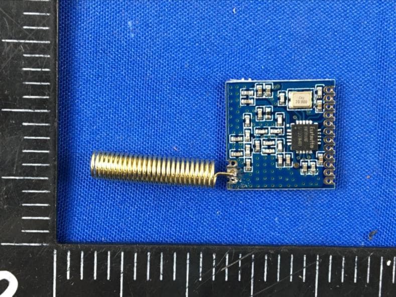
Click to zoom
Application Details
- Equipment Class
- DSC - Part 15 Security/Remote Control Transmitter
- Date of Grant
- Jan 03, 2021
- Application Purpose
- Original Equipment
- Date of Application
- Dec 22, 2020
- Equipment Note
- HW 3000 RF COMMUNICATION MODULE
- Frequency Range
- 433.92000000 - 433.92000000
- Country
- China
Documents & Files
Document Text
Text extracted from the exhibit documents filed with the FCC. Open a document above to read the original.
Users Manual
1 HW3000 433MHZ FSK/GFSK wireless data transceiver module(V3.0) 1. Description This module adopts Neusoft carrier HW3000 series RF device, which is a wireless transceiver chip with high cost performance and high integration in the industry. This module is an industrial-grade low-power sub-1G RF transceiver module. The extremely low receiving current (8mA, low-power receiving mode) plus the industry-leading 0dBm output power can fully guarantee the link performance and products of user communications Low power consumption requirements. At the same time, this module can support the hardware frequency hopping reception function, which can effectively reduce the interference of the environmental radio to the communication signals of this module. 2 2. Features Working frequency band: 433MHz Maximum output power: 0dBm 90mA@0dBm (transmit) Data transmission rate: 10-100kbps FSK, GFSK modulation mode 2.0-3.6V power supply Ultra-low power shutdown mode Digital Received Signal Strength Indication (RSSI) Support auto answer and auto retransmit function Configurable data packet structure (enhanced frame data structure and direct FIFO frame structure) Preamble detection 256 bytes send and receive data FIFO Integrated voltage regulator Hardware frequency hopping reception function Support data whitening, FEC, CRC check Multiple PIPE logic channels 3 3. Application Remote control Industrial control Toy control Wireless PC peripheral equipment 4 4. performance parameters Parameter Minimal Typical Max Unit Condition Working voltage range 2.0 3.3 3.6 V range of working temperature -40+85 °C Current consumption Receive current 18 mA Non-low-consumption receiving mode 8 mA Low-power receiving mode Emission current 90 mA @0dBm Sleep current 3 uA Shutdown current 100 nA RF parameters Module frequency range 433.92MHz Modulation rate 10 100 Kbps ASK Transmit power range -20+20dBm Receive sensitivity -114dBm @data=10kpbs,Fdev=25kHz 5 5. Typical application circuit 6. pin description and size 6 Pin sequence Pin definition I/O 描 述 PIN1 GND Power ground PIN2 GPIO0 I/O General-purpose digital I/O (see the GPIO part of the register description in Chapter 13 of the HW3000 Datasheet for details) PIN3 GPIO1 I/O PIN4 GPIO2 I/O PIN5 VCC Power supply 3.3V, power supply voltage range 2.0V~3.6V PIN6 SDO O SPI serial data output PIN7 SDI I SPI serial data input PIN8 SCK I SPI clock signal PIN9 CSN I SPI chip select signal (active low) PIN10 IRQ O Interrupt output pin (polarity can be configured, the default low level is effective) PIN11 PDN I POWER DOWN mode enable input pin (active high), and module hardware reset pin Power ground PIN12 GND Power ground PIN14 ANT RF antenna output, connect to 50 ohm 433 antenna PIN15 GND Power ground Note: (If the user MCU pin number is really tight, GPIO0, GPIO1, GPIO2 can not be connected; if the number of pins allows, GPIO0, GPIO1, GPIO2 are recommended to receive one of them, but SDO, SDI, SCK, CSN, IRQ , PDN must be connected.) (1) This device may not cause harmful interference. (2) This device must accept any interference received, including interference that may cause undesired operation. FCC Statement This device complies with part 15 of the FCC Rules. Operation is subject to the following two conditions: (1) This device may not cause harmful interference, and (2) this device must accept any interference received, including interference that may cause undesired operation. Changes or modifications not expressly approved by the party responsible for compliance could void the user's authority to operate the equipment. NOTE: This equipment has been tested and found to comply with the limits for a Class B digital device, pursuant to Part 15 of the FCC Rules. These limits are designed to provide reasonable protection against harmful interference in a residential installation. This equipment generates, uses and can radiate radio frequency energy and, if not installed and used in accordance with the instructions, may cause harmful interference to radio communications. However, there is no guarantee that interference will not occur in a particular installation. If this equipment does cause harmful interference to radio or television reception, which can be determined by turning the equipment off and on, the user is encouraged to try to correct the interference by one or more of the following measures: -- Reorient or relocate the receiving antenna. -- Increase the separation between the equipment and receiver. -- Connect the equipment into an outlet on a circuit different from that to which the receiver is connected. -- Consult the dealer or an experienced radio/TV technician for help. FCC Radiation Exposure Statement This modular complies with FCC RF radiation exposure limits set forth for an uncontrolled environment. This transmitter must not be co- located or operating in conjunction with any other antenna or transmitter. If the FCC identification number is not visible when the module is installed inside another device, then the outside of the device into which the module is installed must also display a label referring to the enclosed module. This exterior label can use wording such as the following: “Contains Transmitter Module FCC ID: 2AYEO-HW3000 Or Contains FCC ID: 2AYEO-HW3000” when the module is installed inside another device, the user manual of this device must contain below warning statements; 1. This device complies with Part 15 of the FCC Rules. Operation is subject to the following two conditions: The device has been evaluated to meet general RF exposure requirement. The devicecan be used in portable exposure condition without restriction. 2. Changes or modifications not expressly approved by the party responsible for compliance could void the user's authority to operate the equipment. The devices must be installed and used in strict accordance with the manufacturer's instructions as described in the user documentation that comes with the…
Text truncated - open the document above for the full version.
Cover Letter(s)
C5266091_X10_Ed.1 1/1 ZHEJIANG GOMELONG METER CO., LTD Office of Engineering Technology Federal Communications Commission 7435 Oakland Mills Road Columbia, MD 21046 Date: Dec. 14, 2020 Subject: Request for Confidentiality FCC ID:2AYEO-HW3000 To Whom It May Concern, Pursuant to the provisions of Sections 0.457 and 0.459 of Commission's rules (47CFR0.457, 0.459), we are requesting the Commission to withhold the following attachment(s) as confidential document from public disclosure. Exhibits Long-Term Confidentiality Short-Term Confidentiality ID Label/Location No No Attestation Statement No No External Photos No Block Diagram Schematics Test Report No No Test Setup Photos No User’s Manual Internal Photos Parts List / Tune Up RF Exposure Info Operational Description Cover Letter(s) No No SDR Software / Security Info No Above mentioned document contains detailed system and equipment description are considered as proprietary information in operation of the equipment. The public disclosure of above documents might be harmful to our company and would give competitor an unfair advantage in the market. It is our understanding that all measurement test reports, FCC ID label format and correspondent during certification review process cannot be granted as confidential documents and those information will be available for public review once the grant of equipment authorization is issued. C5266091_X10_Ed.1 1/1 Sincerely, Signature: Name: Yin Youbing Title: Manager
Cover Letter(s)
C5266091_X9_Ed.2 < ZHEJIANG GOMELONG METER CO., LTD > Modular Transmitter Approval Request Federal Communications Commission Equipment Authorization Branch 7435 Oakland Mills Road Columbia, MD 21046 Company name: ZHEJIANG GOMELONG METER CO., LTD FCC ID: 2AYEO-HW3000 Gentlemen, In accordance with 47CFR 15.212 Modular Transmitters and KDB 996369 D01 ‘Module Certification Guide v01r04’. FCC ID:2AYEO-HW3000has been examined against the following requirements. Items to be covered by Single modular transmitters. Requirement per 15.212 and KDB 996369 D01 ‘Modular Certification Guide v02 Explanation from Grantee (do not write yes/no, but explain why product complies/how it is achieved) 1. The radio elements must have the radio frequency circuitry shielded. Physical components and tuning capacitor(s) may be located external to the shield, but must be on the module assembly not compliance 2. The module must have buffered modulation/data inputs to ensure that the device will comply with Part 15 requirements with any type of input signal All modulation and data inputs are buffered by circuitry on the transmitter chip HW3000RF, as is shown in the schematic. 3. The module must contain power supply regulation on the module Power supply regulation is provided by circuitry on the transmitter chip HW3000RF, as is shown in the schematic. 4. The module must contain a permanently attached antenna, or contain a unique antenna connector, and be marketed and operated only with specific antenna(s), per Sections 15.203, 15.204(b), 15.204(c), 15.212(a), 2.929(b) The module contain a permanently attached antenna and spurious emission have been fulfilled. Please reference the exhibition Test Report. 5. The module must demonstrate compliance in a stand- alone configuration Please reference exhibition Test Configuration Photo for the stand-alone test configuration. 6. The module must be labelled with its permanently affixed FCC ID label, or use an electronic display (See KDB Publication 784748 about labelling requirements) The instruction on the labelling rule of the end product has been stated in the Users manual of this module. Please also see the exhibition Label Sample. 7. The module must comply with all specific rules applicable to the transmitter including all the conditions provided in the integration instructions by the grantee The required FCC rule has been fulfilled and all the instructions for maintaining compliance has been clearly stated in the Users Manual. 8. The module must comply with RF exposure requirements Please refer exhibition RF Exposure for thecomplianceofMPERFexposurerule. Date: 2020-12-15Name:Yin Youbing Title:Manager Signature of applicant
External Photos
Antenna FCC ID: 2AYEO-HW3000
ID Label/Location Info
FCC ID Label Information 1. Label location: 2. FCC ID Label: FCC ID:2AYEO-HW3000 FCCID Label Location
Internal Photos
Antenna FCC ID: 2AYEO-HW3000
RF Exposure Info
RF Exposure Letter According to 447498 D01 General RF Exposure Guidance v05 The 1‐g and 10‐g SAR test exclusion thresholds for 100 MHz to 6 GHz at test separation distances ≤ 50 mm are determined by: [(max. power of channel, including tune‐up tolerance, mW)/(min. test separation distance, mm)] ·[√f(GHz)] ≤ 3.0 for 1‐g SAR and ≤ 7.5 for 10‐g extremity SAR, where f(GHz) is the RF channel transmit frequency in GHz Power and distance are rounded to the nearest mW and mm before calculation The result is rounded to one decimal place for comparison According to KDB789033 D02 EIRP(dBm)=E(dBuV/m)-95.2, so pt=83.89-95.2(dBm )=0.07 mW at 433.92MHz So (0.07mW/5mm)x √0.43392GH z =0.009<3 Then SAR evaluation is not required FCC ID: 2AYEO-HW3000
Test Report
Shenzhen CTL Testing Technology Co., Ltd. Tel: +86-755-89486194 E-mail: [email protected] TEST REPORT 47 CFR FCC Part 15 Subpart C 15.231 Report Reference No. ................. : CTL2011112071-WF Compiled by: ( position+printed name+signature) Happy Guo (File administrators) Tested by: ( position+printed name+signature) Gray Gao (Test Engineer) Approved by: ( position+printed name+signature) Ivan Xie (Manager) Product Name .............................. : HW 3000 RF COMMUNICATION MODULE Model/Type reference ................. : HW3000 List Model(s) ................................ : N/A Trade Mark ................................... : N/A FCC ID .......................................... : 2AYEO-HW3000 Applicant’s name ........................ : ZHEJIANG GOMELONG METER CO., LTD Address of applicant .................. : XIANGYANG INDUSTRIAL AREA, YUEQING , CHINA Test Firm ...................................... : Shenzhen CTL Testing Technology Co., Ltd. Address of Test Firm .................. : Floor 1- A, Baisha Technology Park, No.3011, Shahexi Road, Nanshan District, Shenzhen, China 518055 Test specification ........................ : Standard ........................................ : 47 CFR FCC Part 15 Subpart C 15.231 TRF Originator .............................. : Shenzhen CTL Testing Technology Co., Ltd. Master TRF ................................... : Dated 2011-01 Date of receipt of test item ......... : Nov. 25, 2020 Date of sampling ......................... : Nov. 25, 2020 Date of Test Date ......................... : Nov. 25, 2020–Dec. 09, 2020 Data of Issue ................................ : Dec. 09, 2020 Result ........................................... : Pass Shenzhen CTL Testing Technology Co., Ltd. All rights reserved. This publication may be reproduced in whole or in part for non-commercial purposes as long as the Shenzhen CTL Testing Technology Co., Ltd. is acknowledged as copyright owner and source of the material. Shenzhen CTL Testing Technology Co., Ltd. takes no responsibility for and will not assume liability for damages resulting from the reader's interpretation of the reproduced material due to its placement and context. V1.0 Page 2 of 22 Report No.: CTL2011112071-WF TEST REPORT Test Report No. : CTL2011112071-WF Dec. 09, 2020 Date of issue Equipment under Test : HW 3000 RF COMMUNICATION MODULE Sample No. CTL201111207-1-S001 Model /Type : HW3000 Listed Models : N/A Applicant : ZHEJIANG GOMELONG METER CO., LTD Address : XIANGYANG INDUSTRIAL AREA, YUEQING , CHINA Manufacturer : ZHEJIANG GOMELONG METER CO., LTD Address : XIANGYANG INDUSTRIAL AREA, YUEQING , CHINA Test result Pass * * In the configuration tested, the EUT complied with the standards specified page 5. The test results presented in this report relate only to the object tested. This report shall not be reproduced, except in full, without the written approval of the issuing testing laboratory. V1.0 Page 3 of 22 Report No.: CTL2011112071-WF ** Modified History ** Version Description Issued DataReport No. Remark Version 1.0 Initial Test Report Release2020-12-09 CTL2011112071-WF Tracy Qi V1.0 Page 4 of 22 Report No.: CTL2011112071-WF Table of Contents Page 1. SUMMARY............................................................................................................................................................ 5 1.1. TEST STA N DA R D S.......................................................................................................................................................... 5 1.2. TEST DESCRIPTION ........................................................................................................................................................ 5 1.3. TEST FACILITY .............................................................................................................................................................. 6 1.4. STATEMENT OF THE MEASUREMENT UNCERTAINTY ............................................................................................................... 6 2. GENERAL INFORMATION ....................................................................................................................................... 8 2.1. ENVIRONMENTAL CONDITIONS ........................................................................................................................................ 8 2.2. GENERAL DESCRIPTION OF EUT ...................................................................................................................................... 8 2.3. EQUIPMENTS USED DURING THE TEST .............................................................................................................................. 8 2.4. RELATED SUBMITTAL(S) / GRANT (S) ................................................................................................................................ 9 2.5. MODIFICATIONS ........................................................................................................................................................... 9 3. TEST CONDITIONS AND RESULTS ......................................................................................................................... 10 3.1. CONDUCTED EMISSION (AC MAIN) ............................................................................................................................... 10 3.2. RADIATED EMISSION ................................................................................................................................................... 13 3.3. 20DB BANDWIDTH ..................................................................................................................................................... 18 3.4. DEACTIVATION TIME ................................................................................................................................................... 19 3.5. ANTENNA REQUIREMENT .............................................................…
Text truncated - open the document above for the full version.
Test Setup Photos
FCC ID: 2AYEO-HW3000
Contact Information
Applicant
Yin youbing
Technical Contact
Test Firm
Shenzhen CTL Testing Technology Co., Ltd.Tracy Qi
[email protected]86-755-89486194
Technical Specifications
| # | Rule Parts | Frequency Range | Power Output |
|---|---|---|---|
| 1 | 15.231 | 433.92 MHz - 433.92 MHz | - |