2AYFF-HUB01Remote care Solution HUB
Pink Nectarine Health AB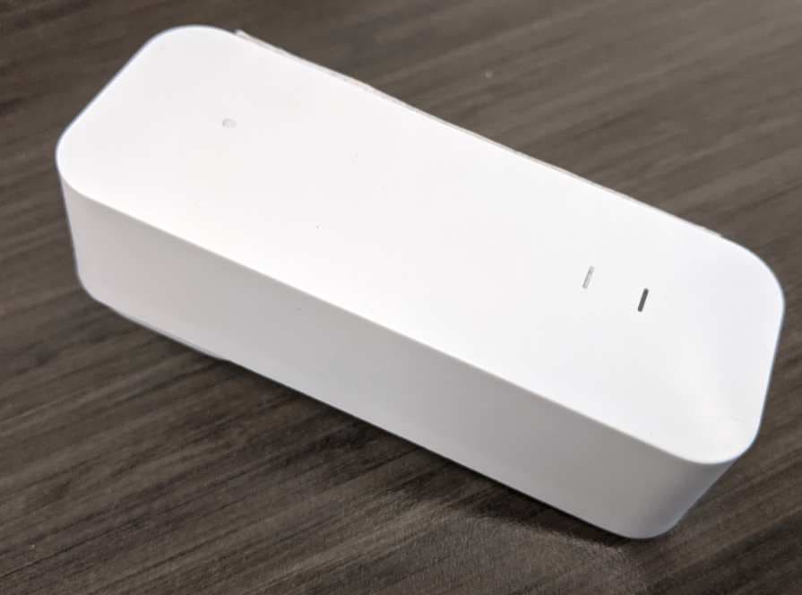
Click to zoom
Application Details
- Equipment Class
- NII - Unlicensed National Information Infrastructure TX
- Date of Grant
- Feb 24, 2021
- Application Purpose
- Original Equipment
- Date of Application
- Feb 24, 2021
- Equipment Note
- Remote care Solution HUB
- Frequency Range
- 5745.00000000 - 5825.00000000
- Company
- Pink Nectarine Health AB
- Country
- Sweden
Documents & Files
Document Text
Text extracted from the exhibit documents filed with the FCC. Open a document above to read the original.
Users Manual
Manual Manual1 Requirements2 Installation and setup2 LED behaviour6 Troubleshooting6 Reset wristband6 The Wristband7 The Hub (and Satellite)7 Support8 Document version: 1.01 Requirements Electrical outlets: AC: 100-240V 50/60Hz Phone: Android 10 or later, iOS 14 or later (this might change with future app releases). Wi-Fi: 2,4 Ghz or 5 Ghz network (supports standards: 802.11a/b/g/n/ac) Installation and setup Install the “Nectarine Health” app from Google Play or App Store. You will need Bluetooth enabled on your phone to communicate settings to the Hub. Before installing the system into your home, you will need your Wi-Fi SSID (name of your home wireless network) and your Wi-Fi password. Your Wi-Fi SSID and Wi-Fi password is often located on the back of your Wi-Fi router if it is supplied by your internet provider. Login with the account created at purchase (Home Admin account), select the subscription you want to install. Give the app access to the requested features. Document version: 1.02 Open up the box containing the Hub and scan the QR code on the back of the unit with the Nectarine Health app. Then plug the Hub into a wall socket. Select the room from the list (or write a custom name) where you will place it. Your phone needs to be within 2 meters of the unit for the app to be able to connect to it via Bluetooth. The app will ask you to choose the Wi-Fi network you want to pair the Hub to; enter the password for the selected network when prompted. This information will then be sent to the Hub. If it fails, please retry and double check credentials. After this is done, you will get the option to add Satellites or finish the setup. The Hub will show its Wi-Fi signal strength, and the app will instruct you to move it closer to the router if the signal is too low. The Satellites will connect to the Hub via Bluetooth or connect to another Satellite if the Hub is not in range. Therefore, it’s recommended to place Hubs and Satellites in rooms adjacent to each other and to think of it as a chain. Document version: 1.03 Next, you will be asked to “add a Wearer”, the person who will be wearing the wristband. You will be asked for their name, email and mobile phone number. The Wearer needs to accept the invitation sent to their email and approve the terms and conditions. When they have done that, they will be available for Wristband assignment in your app. Document version: 1.04 Tap the “Add” button in the “System” overview. Select “Wristband” and select the person you want to assign the Wristband to. Now you can also add additional carers who will be able to see alerts and respond to them. You will need to add their name, email and phone number. An invite will be sent via email that needs to be accepted by the user to access the system. The admin is automatically also a carer in the systems they manage. In the “System” tab, you can see signal status of Hubs and Satellites and battery status of Wearers’ wristbands. Note: LED on Hubs and Satellites will turn off after installation to not disturb. Document version: 1.05 LED behaviour These are the scenarios of different lights during setup and explanations: ●Blue steady light - ready to be provisioned/installed, not connected to Wi-Fi. ●White steady light - ready to be provisioned/installed, connected to Wi-Fi. ●Blue flashing light - connected with app and awaiting further instructions. ●Flashing green light - provisioning/installation in progress. ●Green steady light - provisioned (will restart and turn off lights). ●Red light - provisioning failed, will return to provision mode (Blue or White steady light). Note: Status of Hubs and Satellites will be available in the app. If something happens that requires attention, an alert in the app will be created. LED’s are turned off during normal operation. Troubleshooting Please visit our FAQ (www.nectarinehealth.com/support) In the Nectarine Health App under “System” view (available to Home Admins), you can also get guidance for troubleshooting the system. Reset wristband If you need to re-assign the wristband to another user, or if you are having issues with assigning a wristband, you can reset the wristband. To trigger a factory reset, the user must perform following sequence of actions: 1.Press button → white LED blinks 2.Hold button pressed for 7 s → blue LED blinks (informing to release) Document version: 1.06 3.Release button for 5 s → blue LED blinks (informing to push) 4.Press button and hold for 4 s → blue LED blinks (informing to release) 5.Release button → red LED blinks Green LED blinks when restarted in unprovisioned mode. During step 2 – 5, there is a timeout value of 3 s (from the first blink). If the required action is not performed within 3 s after the LED indication started, the factory reset is aborted. An LED blink is a 3 times loop of 100 ms on, 500 ms off. Below is an illustration of the action sequence for performing factory reset. Restart and Reset Hubs and Satellites The button for restarting and factory resetting is located inside a hole on the front side of the Satellite. You will need a paperclip or other thin object to push it. Press the button 1 time to perform a restart of the Hub/Satellite. - LED is cyan steady/blinking if provisioned. - LED is yellow steady/blinking if unprovisioned. Press the button 2 times to switch the image, which will load the previous release if the unit has been updated. Useful for troubleshooting. - LED is blue steady/blinking. Press the button 3 times (within 3 seconds of each button press) to perform a factory reset. Pressing the button more than 3 times will also start the reset process. - LED is red steady. If you press and hold the button for more than 3 seconds the current action will be aborted and signaled with a green steady LED after 3 seconds. But after the third release factory reset cannot be aborted. Document version: 1.07 The Wristband The Wristband is responsible for detecting movement and pressure changes. It gives ins…
Text truncated - open the document above for the full version.
Cover Letter(s)
1(1) 1-27-2021 Attention: Application Examiner RE: Request for Confidentiality Applicant: Pink Nectarine Health AB FCC ID: 2AYFF-HUB01 To Whom It May Concern: Permanent Confidentiality Request is hereby submitted by Pink Nectarine Health AB to withhold permanently from public review certain portions of the application for equipment certification for the referenced FCC identifiers. This request for confidentiality is made pursuant to 47 CFR 0.457(d) and 0.459 of the FCC Rules. In particular, the following sections of the application are to be kept permanently confidential: • Schematics • Block diagram • Operational description • Part list Rationale for request for confidentiality: Pink Nectarine Health AB has invested considerable time and materials in research and development to produce the referenced product. Disclosure of the permanently confidential portions of this application to competitors would not only give them significant competitive advantages in developing similar products, but would also disclose successful implementation of unpublished, leading edge technology developed by us. If you have questions or need further information, please contact the undersigned. Sincerely, Caroline Pierrou Head of Operations Pink Nectarine Health AB Transaction 09222115557441074583Signed CP Document FCC - Confidentiality_pro_forma_HUB_rev2 Main document 1 page Initiated on 2021-01-27 13:32:21 CET (+0100) by Caroline Pierrou (CP) Finalised on 2021-01-27 13:33:39 CET (+0100) Signing parties Caroline Pierrou (CP) Pink Nectarine Health AB Company reg. no. 559233-9740 [email protected] +46733199261 Signed 2021-01-27 13:33:39 CET (+0100) This verification was issued by Scrive. Information in italics has been safely verified by Scrive. For more information/evidence about this document see the concealed attachments. Use a PDF-reader such as Adobe Reader that can show concealed attachments to view the attachments. Please observe that if the document is printed, the integrity of such printed copy cannot be verified as per the below and that a basic print-out lacks the contents of the concealed attachments. The digital signature (electronic seal) ensures that the integrity of this document, including the concealed attachments, can be proven mathematically and independently of Scrive. For your convenience Scrive also provides a service that enables you to automatically verify the document's integrity at: https://scrive.com/verify Verification Transaction 09222115557441074583 1/1
External Photos
Report No. 104476230BOX-001 Pink Nectarine Health AB Co., Ltd Page 3 of 17 Issued: 22-Dec-2020 Revised: None Photo 1 - External Front view of the HUB Photo 2 - External Rear view of the HUB 3.0 Product Photographs 04 08 ED 16.3.15 (15-Oct-20) Mandatory
Internal Photos
Report No. 104476230BOX-001 Pink Nectarine Health AB Co., Ltd Page 5 of 17 Issued: 22-Dec-2020 Revised: None 3.0 Product Photographs Photo 5 - Internal Top view of the HUB PCB and components Photo 6 - Internal Top view of the HUB PCB and components 14 03 08 05 ED 16.3.15 (15-Oct-20) Mandatory
RF Exposure Info
Test report No. 2019843STO-307 Page 2 (8) Intertek Semko AB Torshamnsgatan 43, Box 1103, SE-164 22 Kista, Sweden www.intertek.se Version 1.02 Revision History Test report number Date Description Changes 2019843STO-307 December 15, 2020 First release -- Test report No. 2019843STO-307 Page 3 (8) Intertek Semko AB Torshamnsgatan 43, Box 1103, SE-164 22 Kista, Sweden www.intertek.se Version 1.02 CONTENTS Page 1 Client Information ............................................................................................................... 4 2 Equipment .......................................................................................................................... 4 2.1 Identification of the equipment ................................................................................. 4 3 Test Specifications ............................................................................................................. 5 3.1 Standards ................................................................................................................. 5 3.2 Additions, deviations and exclusions from standards .............................................. 5 4 Summary ............................................................................................................................ 6 5 RF Exposure ....................................................................................................................... 7 5.1 Limits ........................................................................................................................ 7 5.2 Calculations .............................................................................................................. 8 5.3 Results, single transmitter ........................................................................................ 8 5.4 Results, multiple transmitters ................................................................................... 8 Test report No. 2019843STO-307 Page 4 (8) Intertek Semko AB Torshamnsgatan 43, Box 1103, SE-164 22 Kista, Sweden www.intertek.se Version 1.02 1 CLIENT INFORMATION This assessment has been done by request of: Company Pink Nectarine Health AB Munkbron 11 111 28 Stockholm Sweden Name of contact Tobias Linghammar, +46 70 461 48 27 2 EQUIPMENT 2.1 Identification of the equipment Equipment: Remote care solution Type/Model: Hub Brand name: Nectarine Health Manufacturer: Pink Nectarine Health AB Transmitter frequency range: Bluetooth Low Energy: 2402 – 2480 MHz Wi-Fi 2.4 GHz: 2412 – 2472 MHz Wi-Fi 5 GHz: 5150 – 5850 MHz Measured output power to antenna: Bluetooth low energy 1 : +4.9 dBm Wi-Fi 2.4 GHz 2 : +21.9 dBm Wi-Fi 5 GHz 3 : +19.8 dBm Declared output power to antenna: Bluetooth low energy: +6.0 dBm Wi-Fi 2.4 GHz: +22.0 dBm Wi-Fi 5 GHz: +21.0 dBm Antenna gain: Bluetooth low energy: +0.4 dBi Wi-Fi 2.4 GHz: -0.5 dBi Wi-Fi 5 GHz: +0.8 dBi User separation distance: 20 cm Exposure conditions: ☐ Controlled environment (occupational) ☒ Uncontrolled environment (general population) 1 Reference for measurement: Intertek Test Report 2019843STO-304 2 Reference for measurement: Nore Testing Center Report No NTC1712035FV00 3 Reference for measurement: Testing Centre Technology Report No TCT171018E032 Test report No. 2019843STO-307 Page 5 (8) Intertek Semko AB Torshamnsgatan 43, Box 1103, SE-164 22 Kista, Sweden www.intertek.se Version 1.02 3 TEST SPECIFICATIONS 3.1 Standards CFR 47: Code of Federal Regulations Title 47: Telecommunications §1.1307, §1.1310 KDB447498 D01 v06 RSS-102: Radio Frequency (RF) Exposure Compliance of Radiocommunication Apparatus (All Frequency Bands) 3.2 Additions, deviations and exclusions from standards No additions, deviations or exclusions have been made from standards. Test report No. 2019843STO-307 Page 6 (8) Intertek Semko AB Torshamnsgatan 43, Box 1103, SE-164 22 Kista, Sweden www.intertek.se Version 1.02 4 SUMMARY The evaluation has been carried out at the Intertek Semko AB premises in Kista, Sweden. The results in this report apply only to sample tested: Test Result RF Exposure, single transmitter PASS RF Exposure, multiple simultaneous transmitters PASS Test report No. 2019843STO-307 Page 7 (8) Intertek Semko AB Torshamnsgatan 43, Box 1103, SE-164 22 Kista, Sweden www.intertek.se Version 1.02 5 RF EXPOSURE Result, single transmitter: PASS Result, multiple transmitter: PASS 5.1 Limits Reference: CFR 47 §1.1310 TABLE 1—LIMITS FOR MAXIMUM PERMISSIBLE EXPOSURE (MPE) Frequency range (MHz) Electric field strength (V/m) Magnetic field strength (A/m) Power density (mW/cm 2 ) Averaging time (minutes) (A) Limits for Occupational/Controlled Exposure 0.3-3.0 614 1.63 *100 6 3.0-30 1842/f 4.89/f *900/f 2 6 30-300 61.4 0.163 1.0 6 300-1,500 f/300 6 1,500-100,000 5 6 (B) Limits for General Population/Uncontrolled Exposure 0.3-1.34 614 1.63 *100 30 1.34-30 824/f 2.19/f *180/f 2 30 30-300 27.5 0.073 0.2 30 300-1,500 f/1500 30 1,500-100,000 1.0 30 Reference: RSS-102 – Radio Frequency (RF) Exposure Compliance of Radiocommunication Apparatus (All Frequency Bands) Issue 5 Section 2.5.2, RF exposure evaluation is required if the separation distance between the user and/or bystander and the device’s radiating element is greater than 20 cm, except when the device operatesas follows: • below 20 MHz and the source-based, time-averaged maximum e.i.r.p. of the device is equal to or less than 1 W (adjusted for tune-up tolerance); • at or above 20 MHz and below 48 MHz and the source-based, time-averaged maximum e.i.r.p. of the device is equal to or less than 4.49/ƒ 0.5 W (adjusted for tune-up tolerance), where ƒ is in MHz; • at or above 48 MHz and below 300 MHz and the source-based, time-averagedmaximum e.i.r.p. of the device is equal to or less than 0.6 W (adjusted for tune-up tolerance); • at or above 300 MHz and below 6 GHz and the source-based, time-averaged maximum e.i.r.p. of the device is equal to or less than 1.31 x 10 -2 ƒ 0.6834 W (adjusted for tune-up tolerance), where ƒ is …
Text truncated - open the document above for the full version.
Test Report
Test report No. 2019843STO-311 Page 2 (16) Intertek Semko AB Torshamnsgatan 43, Box 1103, SE-164 22 Kista, Sweden www.intertek.se Version 1. 03 Revision History Test report number Date Description Changes 2019843STO-311 December 15, 2020 First release -- Test report No. 2019843STO-311 Page 3 (16) Intertek Semko AB Torshamnsgatan 43, Box 1103, SE-164 22 Kista, Sweden www.intertek.se Version 1. 03 CONTENTS Page 1 Client Information ............................................................................................................... 4 2 Equipment under test (EUT) ............................................................................................... 4 2.1 Identification of the EUT ........................................................................................... 4 2.2 Additional information about the EUT ...................................................................... 5 2.3 Mode of operation during the tests .......................................................................... 5 2.4 Modifications made to improve EMC-characteristics ............................................... 5 3 Test Specifications ............................................................................................................. 6 3.1 Standards ................................................................................................................. 6 3.2 Additions, deviations and exclusions from standards and accreditation ................. 6 3.3 Test site .................................................................................................................... 6 4 Test Summary .................................................................................................................... 7 5 Radiated rf Emission in the frequency-range 1 GHz to 40 GHz ........................................ 8 5.1 Test set-up and test procedure ................................................................................ 8 5.2 Test conditions ......................................................................................................... 8 5.3 Requirements ........................................................................................................... 9 5.4 Test results 1 GHz – 40 GHz, TX .......................................................................... 10 6 Test equipment ................................................................................................................. 16 7 Measurement uncertainty ................................................................................................. 16 8 Test set up and EUT photos ............................................................................................. 16 Test report No. 2019843STO-311 Page 4 (16) Intertek Semko AB Torshamnsgatan 43, Box 1103, SE-164 22 Kista, Sweden www.intertek.se Version 1. 03 1 CLIENT INFORMATION The EUT has been tested by request of Company Pink Nectarine Health AB Munkbron 11 111 28 Stockholm Sweden Name of contact Tobias Linghammar Phone +46 70 461 48 27 2 EQUIPMENT UNDER TEST (EUT) 2.1 Identification of the EUT Equipment: Remote care solution Type/Model: Hub Brand name: Nectarine Health Serial number: HNA0101-T2041397BQ Manufacturer: Pink Nectarine Health AB Transmitter frequency range: 5150 – 5850 MHz Receiver frequency range: 5150 – 5850 MHz Antenna: Internal antenna External antenna Antenna connector: None, internal antenna Yes Antenna gain: +0.8 dBi Rating RF output power: +22 dBm (eirp) Type of modulation: 802.11a/n/ac Temperature range: Category I (General): -20°C to +55°C Category II (Portable equipment): -10°C to +55°C Category III (Equipment for normal indoor use): +5°C to +35°C Other: 0°C to +40°C Transmitter standby mode supported: Yes No Test report No. 2019843STO-311 Page 5 (16) Intertek Semko AB Torshamnsgatan 43, Box 1103, SE-164 22 Kista, Sweden www.intertek.se Version 1. 03 2.2 Additional information about the EUT The EUT employs Wi-Fi 2.4 GHz, Wi-Fi 5 GHz and Bluetooth Low Energy. This test report covers transmitter spurious emission in the frequency range 1 – 40 GHz for Wi-Fi 5 GHz. The Wi-Fi 5 GHz have previously been tested for full compliance in test report number TCT171018E032 by Testing Centre Technology. It was determined by the RF output power and power spectral density from the above-mentioned test report that IEEE 802.11b with 6 Mbps data rate is the worst-case modulation. The EUT consists of the following units: Unit Type Serial number Comment Unit 1 Hub HNA0101-T2041397BQ For radiated emission During the tests the EUT supported following software: Software Version Comment Code Aurora 4.5.25.42 Change-Id: Idc2ffabededf75ab79517ddc46b2e9c 61b2e3c74 85e563927dde7df2292e961f43c9b16 8b6c1402568d4c0557deb846ff2c2fe1 8 bdwlan30.bin 9f2a436dc48e45f98d3bb37cb295a9d 8b352ee006c24582c82d67b6fef6d08 de eeprom_qca9377_1p1_WB396_olpc. bin a62785f32234029f08c81ad28ce6047 2d74f2827361618c4f09a9837d78c88 55 otp30.bin 364900f2e41cb120e1c50c1b167dfbf3 c68c2f274cf6983b36b54706ede13c1c qwlan30.bin 315ac1e2ef6637db584d8135f869ad8f 6db8874d5c4360fbcea9cf6944048dd 1 utf30.bin 2.3 Mode of operation during the tests During the radiated tests the EUT was transmitting a continuous modulated signal, 802.11a with 6 Mbps data rate. The tests were performed on the following channels: CH48 = 5240 MHz CH161 = 5805 MHz 2.4 Modifications made to improve EMC-characteristics No modifications have been made during the tests. Test report No. 2019843STO-311 Page 6 (16) Intertek Semko AB Torshamnsgatan 43, Box 1103, SE-164 22 Kista, Sweden www.intertek.se Version 1. 03 3 TEST SPECIFICATIONS 3.1 Standards Requirements: 47 CFR Part 15: Subpart E: Unlicensed National Information Infrastructure Devices RSS-GEN Issue 5 Amendment 1 (2017): General requirements of compliance of radio apparatus. RSS-247 Issue 2 (2018): Digital Transmission Systems (DTSs), Frequency Hopping Systems (FHSs) and Licence-Exempt Local Area Network (LE-LAN) Devices Test met…
Text truncated - open the document above for the full version.
Test Report
Hotline: 400-6611-140 Tel: 86-755-27673339 Fax: 86-755-27673332 http://www.tct-lab.com TEST REPORT FCC ID: 2AATL-8223A-SR Product: WIFI+BT Module Model No.: 8223A-SR Additional Model No.: N/A Trade Mark: FN-LINK Report No.: TCT171018E032 Issued Date: December 06, 2017 Issued for: FN-LINK TECHNOLOGY LIMITED No.8, Litong Road, Liuyang Economic Development Zone, Liuyang City, Hunan Province, China Issued By: Shenzhen Tongce Testing Lab. 1B/F., Building 1, Yibaolai Industrial Park, Qiaotou, Fuyong, Baoan District, Shenzhen, Guangdong, China TEL: +86-755-27673339 FAX: +86-755-27673332 Note: This report shall not be reproduced except in full, without the written approval of Shenzhen Tongce Testing Lab. This document may be altered or revised by Shenzhen Tongce Testing Lab. personnel only, and shall be noted in the revision section of the document. The test results in the report only apply to the tested sample. Report No.: TCT171018E032 Page 2 of 70 Hotline: 400-6611-140 Tel: 86-755-27673339 Fax: 86-755-27673332 http://www.tct-lab.com TABLE OF CONTENTS 1. Test Certification ..................................................................................... 3 2. Test Result Summary .............................................................................. 4 3. EUT Description ....................................................................................... 5 4. Genera Information .................................................................................. 7 4.1. Test environment and mode ............................................................................................................ 9 4.2. Description of Support Units ......................................................................................................... 10 5. Facilities and Accreditations ................................................................ 11 5.1. Facilities ........................................................................................................................................... 11 5.2. Location............................................................................................................................................ 11 5.3. Measurement Uncertainty .............................................................................................................. 11 6. Test Results and Measurement Data ................................................... 12 6.1. Antenna requirement ...................................................................................................................... 12 6.2. Conducted Emission ....................................................................................................................... 13 6.3. Maximum Conducted Output Power ............................................................................................. 17 6.4. 6dB Emission Bandwidth ............................................................................................................... 21 6.5. 26dB Bandwidth and 99% Occupied Bandwidth ......................................................................... 28 6.6. Power Spectral Density .................................................................................................................. 40 6.7. Band edge ........................................................................................................................................ 53 6.8. Spurious Emission .......................................................................................................................... 59 6.9. Frequency Stability Measurement ................................................................................................. 65 Appendix A: Photographs of Test Setup Appendix B: Photographs of EUT Report No.: TCT171018E032 Page 3 of 70 Hotline: 400-6611-140 Tel: 86-755-27673339 Fax: 86-755-27673332 http://www.tct-lab.com 1. Test Certification Product: WIFI+BT Module Model No.: 8223A-SR Additional Model No.: N/A Trade Mark: FN-LINK Applicant: FN-LINK TECHNOLOGY LIMITED Address: No.8, Litong Road, Liuyang Economic Development Zone, Liuyang City, Hunan Province, China Manufacturer: FN-LINK TECHNOLOGY LIMITED Address: No.8, Litong Road, Liuyang Economic Development Zone, Liuyang City, Hunan Province, China Date of Test: November 06, 2017 to December 05, 2017 Applicable Standards: FCC CFR Title 47 Part 15 Subpart E Section 15.407: 2016 KDB789033 D02 General U-NII Test Procedures New Rules v01r04 The above equipment has been tested by Shenzhen Tongce Testing Lab. and found compliance with the requirements set forth in the technical standards mentioned above. The results of testing in this report apply only to the product/system, which was tested. Other similar equipment will not necessarily produce the same results due to production tolerance and measurement uncertainties. Tested By: Date: December 05, 2017 Brews Xu Reviewed By: Date: December 06, 2017 Joe Zhou Approved By: Date: December 06, 2017 Tomsin Report No.: TCT171018E032 Page 4 of 70 Hotline: 400-6611-140 Tel: 86-755-27673339 Fax: 86-755-27673332 http://www.tct-lab.com 2. Test Result Summary Requirement CFR 47 Section Result Antenna requirement §15.203 PASS AC Power Line Conducted Emission §15.207 PASS Maximum Conducted Output Power §15.407(a) §2.1046 PASS 6dB Emission Bandwidth §15.407(a) §2.1049 PASS 26dB Emission Bandwidth& 99% Occupied Bandwidth §15.407(a) §2.1049 PASS Power Spectral Density §15.407(a) PASS Band edge §15.407(a) PASS Radiated Emission §15.407(a) §2.1053 PASS Frequency Stability §15.407(g) §2.1055 PASS Note: 1. PASS: Test item meets the requirement. 2. Fail: Test item does not meet the requirement. 3. N/A: Test case does not apply to the test object. 4. The test result judgment is decided by the limit of test standard. Report No.: TCT171018E032 Page 5 of 70 Hotline: 400-6611-140 Tel: 86-755-27673339 Fax: 86-755-27673332 http://www.tct-lab.com 3. EUT Description Product: WIFI+BT Module Model No.: 8223A-S…
Text truncated - open the document above for the full version.
Test Setup Photos
Test report no. 2019843STO-320 Annex 1 Page 1 (1) Intertek Semko AB Torshamnsgatan 43, Box 1103, SE-164 22 Kista, Sweden www.intertek.se ANNEX 1 Photos of EUT EUT, fitted with temporary serial cables for programming purpose
Test Setup Photos
Test report no. 2019843STO-321 Annex 2 Page 1 (1) Intertek Semko AB Torshamnsgatan 43, Box 1103, SE-164 22 Kista, Sweden www.intertek.se ANNEX 2 Photos of test setup Test set up radiated emission 30 MHz – 1 GHz Test set up radiated emission above 1 GHz
Test Setup Photos
FCC ID: 2AATL-8223A-SR Test photo Radiated emission FCC ID: 2AATL-8223A-SR Conducted emission
Contact Information
Applicant
Caroline Pierrou(Head of Operations)
Technical Contact
Test Firm
Intertek Semko ABPar Iggstrom
[email protected]+46708750026
Technical Specifications
| # | Rule Parts | Frequency Range | Power Output |
|---|---|---|---|
| 2 | 15E | 5.75 GHz - 5.83 GHz | 87.10 mW |
Other Applications from Pink Nectarine Health AB
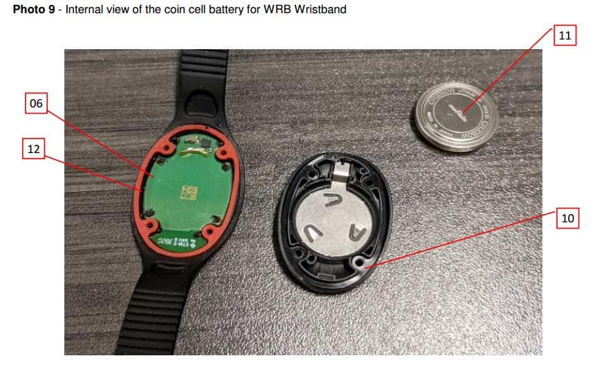
2AYFF-WRB02
Feb 15, 2021Wireless monitoring wristband
Equipment Class
DTS - Digital Transmission System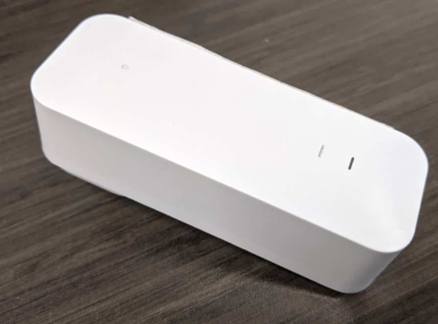
2AYFF-SAT01
Feb 15, 2021Remote Care Solution Satellite
Equipment Class
DTS - Digital Transmission System