2AYFH-OVE-HPHemoPill acute
Ovesco Endoscopy AG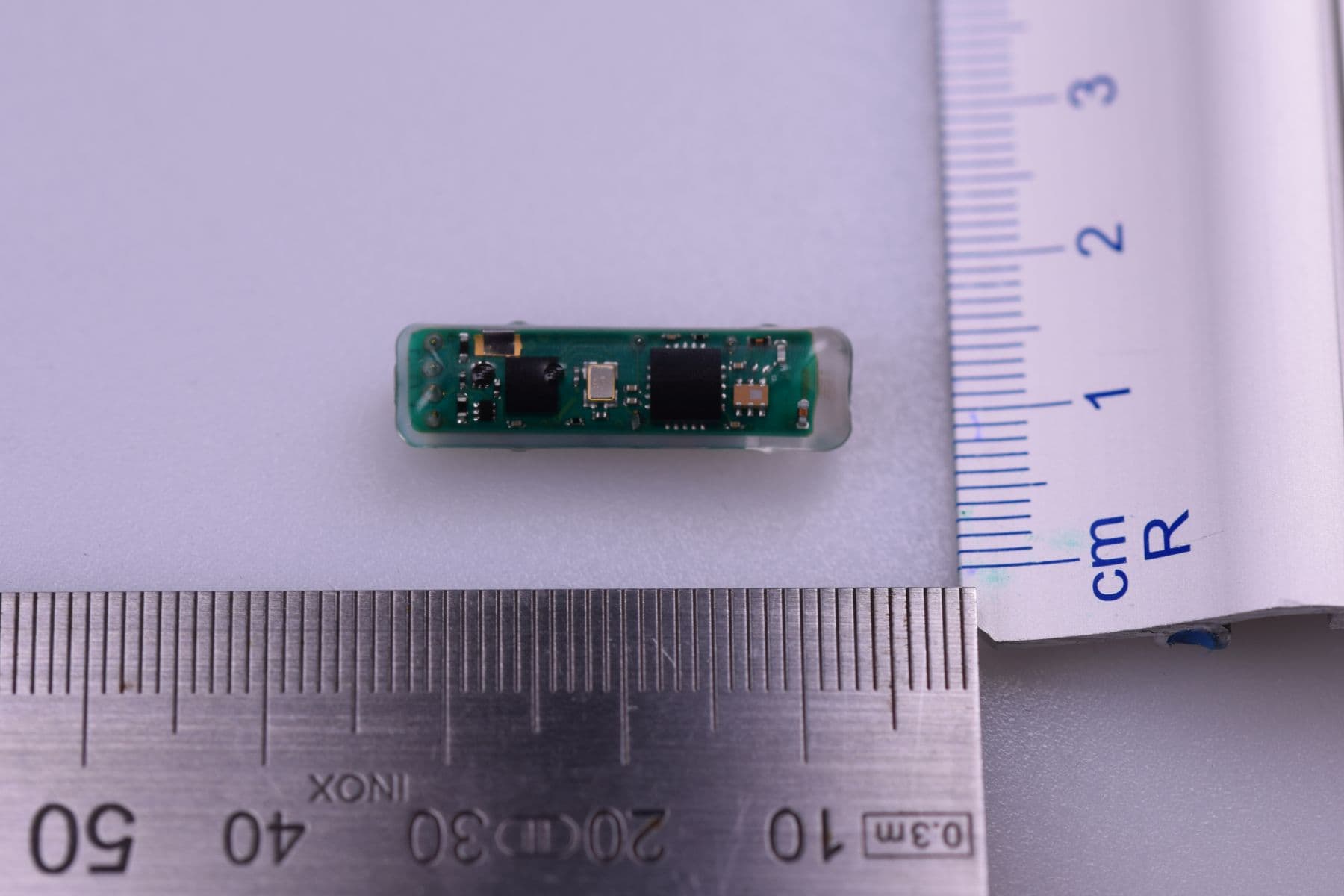
Click to zoom
Application Details
- Equipment Class
- DXX - Part 15 Low Power Communication Device Transmitter
- Date of Grant
- Mar 23, 2021
- Application Purpose
- Original Equipment
- Date of Application
- Mar 23, 2021
- Equipment Note
- HemoPill acute
- Frequency Range
- 434.40000000 - 434.40000000
- Company
- Ovesco Endoscopy AG
- Country
- Germany
Documents & Files
Document Text
Text extracted from the exhibit documents filed with the FCC. Open a document above to read the original.
Users Manual
HemoPill ® ACUTE Instructions for use U.S.A. Ref. No 500.01 Capsule dimensions: Length 26.3 mm Maximum diameter Ø 7.0 mm PRODUCT DESCRIPTION The HemoPill acute is an active diagnostic medical device. The capsule is battery operated and features a housing with a measuring gap containing an optical sensor. The signals of the HemoPill acute sensor correlate with the presence of blood in the measuring gap of the capsule and are transmitted wirelessly to the HemoPill Receiver. The HemoPill acute is able to detect liquid blood (or hematin) in quantities of ≥ 20 ml with a sensitivity and specificity of > 80%*. The HemoPill acute is designed only for use with the HemoPill Receiver (ref. no. 500.20, Ovesco Endoscopy AG). *Data is based on scientific analysis confirmed by a clinical study (DING study). INDICATION The HemoPill acute is used for diagnosis in patients with suspected acute bleeding in the esophagus, stomach, and small intestine. The HemoPill acute is intended for use in adults and young patients aged 14 years and above. There is no clinical data concerning use on patients aged between 14 and 18. The HemoPill acute is administered by swallowing. CONTRAINDICATION Use of the HemoPill acute is contraindicated in the following conditions: • known gastrointestinal obstruction, stricture, fistula, or diverticula • dysphagia or other swallowing disorders • during pregnancy • impaired consciousness that prevents autonomous swallowing of the capsule • in patients with cardiac pacemakers and other implanted electromedical devices COMPLICATIONS The following complications are possible when the HemoPill acute system is used as intended: • aspiration of the capsule on ingestion • delayed excretion, or failure to excrete the capsule (capsule retention) • obstruction of the digestive tract • injury to tissue structures during the passage of the HemoPill acute through the digestive tract. In particular, this may involve: − injury to the mucosa − bleeding, e. g. variceal bleeding − perforations GENERAL INFORMATION Using these instructions for use Carefully read these instructions for use and the instructions for the HemoPill Receiver before using the HemoPill acute. The user should have fully understood how the product works and how it should be handled. The user must ensure that the HemoPill acute system is used and the measured values are interpreted in accordance with the instructions for use. Using this product The product must be used only for its intended purpose. Even if the product is used as intended, side effects may occur. For this reason, Ovesco products should only be used by persons who are qualified and trained to use the specific products for their intended purpose. The HemoPill acute can be used by doctors, nursing staff or medical staff with equivalent training. BEFORE USE 1. Switching on the HemoPill Receiver Switch on the HemoPill Receiver and select the "Connect" menu (see instructions for use for the HemoPill Receiver). 2. Activating the HemoPill acute The HemoPill acute must be activated before it is removed from the blister packaging. The capsule is activated by light in the activation area of the capsule (1). Use the LED light source integrated in the HemoPill Receiver (2). Switch on the LED via the display on the HemoPill Receiver and press the "LED" button in the "Connect" menu. The LED will light up for approx. 5 seconds after you have pressed the button. Figure 1 Place the blister packaging against the left side of the HemoPill Receiver and align the grey triangle markings on the blister and the HemoPill Receiver to each other. Hold the blister immediately next to the LED of the Receiver (fig. 2). If necessary, move the blister slightly around the LED of the Receiver. Figure 2 When the capsule is activated, the light source of the capsule flashes at regular intervals. Note the color of the flashing signal (fig. 3): Flashing blue: HemoPill acute is ready for use. Flashing red: HemoPill acute is defective and must not be used. Figure 3 3. Establishing a data connection Comparing the capsule ID When establishing a data connection, it is important to ensure that the capsule ID shown on the HemoPill Receiver matches the capsule ID on the blister packaging. Connecting to an incorrect HemoPill acute can lead to false negative results. The capsule ID is indicated directly on the blister packaging. The separately enclosed patient labels (four stickers) serve the documentation in the patient file. Figure 4 OVE_HemoPill acute_IFU eng-US_Rev.14_DRAFT_2021-03-23_final.docx;2021-03-24 2/4 Press the "Connect" button in the main menu of the HemoPill Receiver (see instructions for use for the HemoPill Receiver). Select the capsule ID of the HemoPill acute to which you want to establish a connection (1). For the connection, press the "Connect" button next to the corresponding capsule ID (2). Figure 5 The measurement diagram for the selected capsule is now shown on the display of the HemoPill Receiver. USE 1. Handing the HemoPill acute to the patient Handing over the HemoPill acute When handing the capsule to the patient, ensure that it is activated in the blister and is not contaminated. Only remove the paper cover on the rear side of the blister. This can easily be pulled off in one direction. After opening, hand the blister to the patient for the removal of the capsule (fig. 6). The blister packaging is designed to enable the patient to remove the capsule with two fingers. Figure 6 Ensure that the patient holds the capsule in the center, on the sides, and does not obscure the area of the flashing measuring gap! Figure 7 Checking the data reception after handing to the patient After handing the capsule to the patient, check that there is still a data connection between the HemoPill acute and HemoPill Receiver. To do this, ensure that the blue LED on the HemoPill Receiver has lit up at least twice before the patient swallows the capsule. 2. Ingesting the capsule Do not bite on the capsule In…
Text truncated - open the document above for the full version.
Test Report
The test results relate only to the individual items which have been tested. This report shall not be reproduced in parts without the written approval of the testing laboratory © Copyright: All rights reserved by CETECOM Annex 3: External photographs 17-1-0202201T01a-A3 Number of pages: 14 Date of Report: 2021-Mar-04 Testing company: CETECOM GmbH Im Teelbruch 116 45219 Essen Germany Tel. + 49 (0) 20 54 / 95 19-0 Fax: + 49 (0) 20 54 / 95 19-150 Applicant: Ovesco Endoscopy AG Product: HemoPill acute / HemoPill Receiver / HemoPill Printer (no wireless communication) Type: medical swallowable capsule / Medical device to receiving and displaying values measured by the HemoPill acute / HemoPill Printer Model: HemoPill acute / HemoPill Receiver / HemoPill Printer (no wireless communication) FCC ID: 2AYFH-OVE-HP IC: - Testing has been carried out in accordance with: FCC Regulations: Title 47, Subpart 15.231(e) ISED Regulations: RSS-210, Issue 10 (2019-12), chapter A1.4; RSS-Gen, Issue 5 (2018-04) Deviations, modifications or clarifications (if any) to above mentioned documents are written in each section under "Test method and limit". 17-1-0202201T01a-A3 CETECOM_TR17_1_0202201T01a_A3 2 / 14 Table of Contents 1 External photographs of Main device under test (EUT/DUT) ..................................................................................................3 2 External photographs of Accessories .....................................................................................................................................12 17-1-0202201T01a-A3 CETECOM_TR17_1_0202201T01a_A3 3 / 14 1 External photographs of Main device under test (EUT/DUT) Photograph 1: EUT 1_Top view Photograph 2: EUT 1_Bottom side view 17-1-0202201T01a-A3 CETECOM_TR17_1_0202201T01a_A3 4 / 14 Photograph 3: EUT 2_Top side view Photograph 4: EUT 2_Bottom side view 17-1-0202201T01a-A3 CETECOM_TR17_1_0202201T01a_A3 5 / 14 Photograph 5: EUT 2_Top side view Photograph 6: EUT 2_Bottom side view 17-1-0202201T01a-A3 CETECOM_TR17_1_0202201T01a_A3 6 / 14 Photograph 7: EUT 3_Front side view Photograph 8: EUT 3_Left side view 17-1-0202201T01a-A3 CETECOM_TR17_1_0202201T01a_A3 7 / 14 Photograph 9: EUT 3_Right side view Photograph 10: EUT 3_Top side view 17-1-0202201T01a-A3 CETECOM_TR17_1_0202201T01a_A3 8 / 14 Photograph 11: EUT 3_Bottom side view Photograph 12: EUT 3_Rear side view 17-1-0202201T01a-A3 CETECOM_TR17_1_0202201T01a_A3 9 / 14 Photograph 13: EUT 4_Front side view Photograph 14: EUT 4_Left side view 17-1-0202201T01a-A3 CETECOM_TR17_1_0202201T01a_A3 10 / 14 Photograph 15: EUT 4_Right side view Photograph 16: EUT 4_Top side view 17-1-0202201T01a-A3 CETECOM_TR17_1_0202201T01a_A3 11 / 14 Photograph 17: EUT 4_Top side view Photograph 18: EUT 4_Rear side view 17-1-0202201T01a-A3 CETECOM_TR17_1_0202201T01a_A3 12 / 14 2 External photographs of Accessories Photograph 1: AE1, Battery pack. Front view. Photograph 2: AE1 (Battery pack). Rear view. Photograph 3 17-1-0202201T01a-A3 CETECOM_TR17_1_0202201T01a_A3 13 / 14 Photograph 4: AE 2 & 3 (net power supply & power cord USA). Photograph 5: AE 4 & 5 (net power supply cable & net power supply) 17-1-0202201T01a-A3 CETECOM_TR17_1_0202201T01a_A3 14 / 14 Photograph 6: CAB 1 (USB cable) End of Annex 3
Test Report
The test results relate only to the individual items which have been tested. This report shall not be reproduced in parts without the written approval of the testing laboratory © Copyright: All rights reserved by CETECOM Annex 1: Measurement diagrams 17-1-0202201T01a-A1 Number of pages: 14 Date of Report: 2021-Mar-04 Testing company: CETECOM GmbH Im Teelbruch 116 45219 Essen Germany Tel. + 49 (0) 20 54 / 95 19-0 Fax: + 49 (0) 20 54 / 95 19-150 Applicant: Ovesco Endoscopy AG Product: HemoPill acute / HemoPill Receiver / HemoPill Printer (no wireless communication) Type: medical swallowable capsule / Medical device to receiving and displaying values measured by the HemoPill acute / HemoPill Printer Model: HemoPill acute / HemoPill Receiver / HemoPill Printer (no wireless communication) FCC ID: 2AYFH-OVE-HP IC: - Testing has been carried out in accordance with: FCC Regulations: Title 47, Subpart 15.231(e) ISED Regulations: RSS-210, Issue 10 (2019-12), chapter A1.4; RSS-Gen, Issue 5 (2018-04) Deviations, modifications or clarifications (if any) to above mentioned documents are written in each section under "Test method and limit". 17-1-0202201T01a-A1 CETECOM_TR17_1_0202201T01a_A1 2 / 14 Table of Contents 1 Measurement diagrams ...........................................................................................................................................................3 1.1 Fundamental field strength (15.231(e)) ............................................................................................................................3 1.2 Radiated magnetic field strength measurements (f < 30 MHz) .........................................................................................4 1.3 Radiated emissions in the frequency range 30 to 1000 MHz ............................................................................................6 1.4 Radiated emissions in the frequency range above 1000 MHz ...........................................................................................8 1.5 20dBc bandwidth & 99% occupied bandwidth ................................................................................................................11 1.6 Duty-Cycle correction ......................................................................................................................................................12 1.7 Transmission characteristics ............................................................................................................................................13 17-1-0202201T01a-A1 CETECOM_TR17_1_0202201T01a_A1 3 / 14 1 Measurement diagrams 1.1 Fundamental field strength (15.231(e)) Diagram 3.02: EUT at lying position (see limit in the main test report) AV-Value: 86.27 – 25.27 dB (Timing) = 61 dBμV/m@3m Limit of FCC15.231(e) for fundamental emission at 434.43 MHz = 72.88 dBμV/m Verdict: Passed. Remark: EUT has only been tested at lying position due to its small size. 0 10 20 30 40 50 60 70 80 90 420 425 430 435 440 445 450 Level in dBμV/m Frequ en cy in M Hz 434,430000 MHz 86,274 dBμV/m 17-1-0202201T01a-A1 CETECOM_TR17_1_0202201T01a_A1 4 / 14 1.2 Radiated magnetic field strength measurements (f < 30 MHz) 2.01_RSE_TX_CW_mode_EUT_standing Common Information Test description: Magnetic Field Strength Measurement related to 30/300 m distance Test site and distance: Ref.-Nr. 441 Semi Anechoic Room (SAR) with 3 m measurement distance Version of Testsoftware: EMC32 V9.25.0 Distance correction: used accord. table, pls. see test report Used filter: bypass Test specification: FCC 15.209/RSS-Gen, Issue 5 Operator: GHu Environmental Conditions:: Humidity : 40% rH; Temperature: 21 °C EUT: 17-1-02022S17_C01 Operating Mode: TX CW Power during tests: 4.65 V external battery EUT Setup: EUT lying (EUT has only been tested at lying position due to its small size) Verdict: Passed -50 -40 -30 -20 -10 0 10 20 30 40 50 60 9k203050100k2003005001M2M3M5M10M2030M Level in dBμV/m Frequ en cy in H z FCC15.209_Magnetic_Field 17,400 kH z -22,784 dBμV/m 35,000 kH z -31,595 dBμV/m 52,520 kH z -35,203 dBμV/m 29,002000 MH z 19,851 dBμV/m 17-1-0202201T01a-A1 CETECOM_TR17_1_0202201T01a_A1 5 / 14 2.02_RSE_TX_normal_mode_EUT_lying Common Information Test description: Magnetic Field Strength Measurement related to 30/300 m distance Test site and distance: Ref.-Nr. 441 Semi Anechoic Room (SAR) with 3 m measurement distance Version of Testsoftware: EMC32 V9.25.0 Distance correction: used accord. table, pls. see test report Used filter: bypass Test specification: FCC 15.209/RSS-Gen, Issue 5 Operator: GHu Environmental Conditions:: Humidity : 40% rH; Temperature: 21 °C EUT: 17-1-02022S15_C01 + 17-1-02022S02_C01 Operating Mode: TX normal mode Power during tests: 4.65 V internal battery EUT Setup: EUT lying (EUT has only been tested at lying position due to its small size) Verdict: Passed -50 -40 -30 -20 -10 0 10 20 30 40 50 60 9k203050100k2003005001M2M3M5M10M2030M Level in dBμV/m Frequ en cy in H z FCC15.209_Magnetic_Field 17,400 kH z -23,313 dBμV/m 26,600 kH z -30,815 dBμV/m 35,080 kH z -33,419 dBμV/m 53,320 kH z -31,448 dBμV/m 106,520 kHz -35,708 dBμV/m 79,880 kH z -33,811 dBμV/m 514,000 kHz 1,688 dBμV/m 28,626000 MH z 20,057 dBμV/m 17-1-0202201T01a-A1 CETECOM_TR17_1_0202201T01a_A1 6 / 14 1.3 Radiated emissions in the frequency range 30 to 1000 MHz 3.11_RSE_TX_CW_mode_EUT_lying Common Information Test description: Electric Field Strength Measurement Test site and distance: Ref.-Nr. 441 Semi Anechoic Room (SAR) with 3 m measurement distance Version of Testsoftware: EMC32 V9.25.0 Distance correction: not used Used filter: not used Test specification: FCC §15.209/§15.231 / RSS-210, Issue10 / RSS-Gen, Issue 5 Operator: GHu Environmental Conditions:: Humidity : 40% rH; Temperature: 21 °C EUT: 17-1-02022S17_C01 Operating Mode: TX CW Power during tests: 4.65 V external battery EUT Setup: EUT lying (EUT has only been tested at lying position due to its small size) Verdict: Passed Final_Result Freque…
Text truncated - open the document above for the full version.
Test Report
Test Report 17-1-0202201T01a Number of pages: 26 Date of Report: 2021-Mar-11 Testing company: CETECOM GmbH Im Teelbruch 116 45219 Essen Germany Tel. + 49 (0) 20 54 / 95 19-0 Fax: + 49 (0) 20 54 / 95 19-150 Applicant: Ovesco Endoscopy AG Product: HemoPill acute / HemoPill Receiver / HemoPill Printer (no wireless communication) Type: medical swallowable capsule / Medical device to receiving and displaying values measured by the HemoPill acute / HemoPill Printer Model: HemoPill acute / HemoPill Receiver / HemoPill Printer (no wireless communication) FCC ID: 2AYFH-OVE-HP IC: - Testing has been carried out in accordance with: FCC Regulations: Title 47, Subpart 15.231(e) ISED Regulations: RSS-210, Issue 10 (2019-12), chapter A1.4; RSS-Gen, Issue 5 (2018-04) Deviations, modifications or clarifications (if any) to above mentioned documents are written in each section under "Test method and limit". Tested Technology: SRD Test Results: ☒ The EUT complies with the requirements in respect of all parameters subject to the test. The test results relate only to devices specified in this document Signatures: Dipl.-Ing. Christian Lorenz M.Sc. Guangcheng Huang Senior Test Manager Test manager Authorization of test report Responsible of test report Test Report 17-1-0202201T01a CETECOM_TR17_1_0202201T01a 2 / 26 Table of Contents Table of Annex...................................................................................................................................................................................3 1 General information ................................................................................................................................................................4 1.1 Disclaimer and Notes .........................................................................................................................................................4 1.1. Summary of Test Results ...................................................................................................................................................5 1.2. Summary of Test Methods ................................................................................................................................................5 2 Administrative Data .................................................................................................................................................................6 2.1 Identification of the Testing Laboratory ............................................................................................................................6 2.2 General limits for environmental conditions .....................................................................................................................6 2.3 Test Laboratories sub-contracted ......................................................................................................................................6 2.4 Organizational Items .........................................................................................................................................................6 2.5 Applicant’s details .............................................................................................................................................................6 2.6 Manufacturer’s details ......................................................................................................................................................6 2.7 EUT: Type, S/N etc. and short descriptions used in this test report ..................................................................................7 2.8 Auxiliary Equipment (AE): Type, S/N etc. and short descriptions ......................................................................................7 2.9 Connected cables ..............................................................................................................................................................7 2.10 Software .......................................................................................................................................................................7 2.11 EUT set-ups ..................................................................................................................................................................7 2.12 EUT operation modes ...................................................................................................................................................8 3 Equipment under test (EUT) ....................................................................................................................................................9 3.1 General Data of Main EUT as Declared by Applicant .........................................................................................................9 3.2 Detailed Technical data of Main EUT as Declared by Applicant ......................................................................................10 3.3 Modifications on Test sample..........................................................................................................................................10 4 Measurements .......................................................................................................................................................................11 4.1 Radiated field strength emissions below 30 MHz ...........................................................................................................11 4.2 Radiated field strength emissions 30 MHz – 1 GHz .........................................................................................................15 4.3 Radiated field strength emissions above 1 GHz ..............................................................................................................18 4.4 Emission Bandwidth 20 dB ..........................................................................................................................…
Text truncated - open the document above for the full version.
Test Setup Photos
The test results relate only to the individual items which have been tested. This report shall not be reproduced in parts without the written approval of the testing laboratory © Copyright: All rights reserved by CETECOM Annex 4: Test setup photographs 17-1-0202201T01a-A4 Number of pages: 6 Date of Report: 2021-Mar-04 Testing company: CETECOM GmbH Im Teelbruch 116 45219 Essen Germany Tel. + 49 (0) 20 54 / 95 19-0 Fax: + 49 (0) 20 54 / 95 19-150 Applicant: Ovesco Endoscopy AG Product: HemoPill acute / HemoPill Receiver / HemoPill Printer (no wireless communication) Type: medical swallowable capsule / Medical device to receiving and displaying values measured by the HemoPill acute / HemoPill Printer Model: HemoPill acute / HemoPill Receiver / HemoPill Printer (no wireless communication) FCC ID: 2AYFH-OVE-HP IC: - Testing has been carried out in accordance with: FCC Regulations: Title 47, Subpart 15.231(e) ISED Regulations: RSS-210, Issue 10 (2019-12), chapter A1.4; RSS-Gen, Issue 5 (2018-04) Deviations, modifications or clarifications (if any) to above mentioned documents are written in each section under "Test method and limit". 17-1-0202201T01a-A4 CETECOM_TR17_1_0202201T01a_A4 2 / 6 Table of Contents 1 Test setup photographs ...........................................................................................................................................................3 17-1-0202201T01a-A4 CETECOM_TR17_1_0202201T01a_A4 3 / 6 1 Test setup photographs Photograph 1: EUT Setup 1 Magnetic Field Measurements in the Semi anechoic chamber Photograph 2: EUT Setup 2 Magnetic Field Measurements in the Semi anechoic chamber 17-1-0202201T01a-A4 CETECOM_TR17_1_0202201T01a_A4 4 / 6 Photograph 3: Overview of EUT Setup Magnetic Field Measurements in the Semi anechoic chamber Photograph 4: Overview of EUT Test Setup 1 in the semi-anechoic chamber, Radiated interference field strength 17-1-0202201T01a-A4 CETECOM_TR17_1_0202201T01a_A4 5 / 6 x Photograph 5: Overview of EUT Test Setup 2 in the anechoic chamber, Radiated interference field strength Photograph 6: EUT Test Setup 1 in the fully anechoic chamber, Radiated interference field strength 17-1-0202201T01a-A4 CETECOM_TR17_1_0202201T01a_A4 6 / 6 Photograph 7: EUT Test Setup 1 in the fully anechoic chamber, Radiated interference field strength Photograph 8: Overview of EUT Test Setup 1 in the fully anechoic chamber, Radiated interference field strength End of Annex 4
Contact Information
Applicant
Christoph Damm(Head of Quality Management & Regulatory Affairs)
Test Firm
cetecom advanced GmbHGerald Schmidt
Technical Specifications
| # | Rule Parts | Frequency Range | Power Output |
|---|---|---|---|
| 1 | 15C | 434.4 MHz - 434.4 MHz | - |
Other Applications from Ovesco Endoscopy AG
2AYFHHP2
Jul 04, 2024Swallowable medical capsule to detect blood
Equipment Class
DSC - Part 15 Security/Remote Control Transmitter