2AYN5LM-H349WIRELESS DOORBELL
NINGBO LONGMARCH IMPORT & EXPORT CO.,Ltd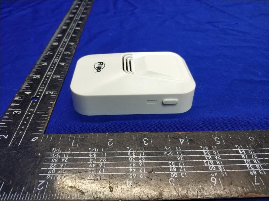
Click to zoom
Application Details
- Equipment Class
- DSC - Part 15 Security/Remote Control Transmitter
- Date of Grant
- Jan 31, 2021
- Application Purpose
- Original Equipment
- Date of Application
- Jan 31, 2021
- Equipment Note
- WIRELESS DOORBELL
- Frequency Range
- 433.92000000 - 433.92000000
- Country
- China
Documents & Files
Document Text
Text extracted from the exhibit documents filed with the FCC. Open a document above to read the original.
Users Manual
Wireless Doorbell With Motion Sensing LED Security Light BATTERY INSTALLATION PRODUCT INSTALLATION PAIRING RECEIVER & DOORBELL SET-UP Figure A Receiver - Front Figure B Receiver - Rear Doorbell Receiver Doorbell Button With LED Light Screws Dry Wall Anchors Set of Hook & Loop Adhesives 1 1 2 2 2 QuantityPart Screw Dry Wall Anchor Figure C Doorbell Button- Front Figure E Doorbell Button - Rear Volume Chime Selection Pairing Button Pairing Button Battery Compartment LED Security Light Motion Sensing On/ Off Switch Battery Cover Screws RECEIVER – Remove the battery cover located on the rear of the Receiver (Figure B). Install 3 AAA batteries according to the polarity indicated in each battery slot. Replace the battery cover. For best result, use alkaline batteries. DOORBELL – The battery compartment is located on the rear of the Doorbell (Figure C). Use a Philips head screwdriver to remove the two screws holding the cover in place. Remove the cover and install 3 AAA batteries according to the polarity indicated in each battery slot. Replace the cover, reinstall the screws and tighten. For best result, use alkaline batteries. IMPORTANT Your Receiver and Doorbell have pre-installed batteries. Remove the battery insulator strips from both doorbell receiver and doorbell button battery compartment before first use. Screws, drywall anchors and hook and loop connectors are included with your product. You can choose to use any of the attachments, but if possible, use of a screw is preferable. The Receiver and Doorbell can connect wirelessly up to 100’, but distances may vary based on the number and composition of walls between the Receiver and Doorbell. Your Receiver and Doorbell are not paired when first removed from packaging. To pair, press and hold the Pairing Button located on the right side of the Receiver for 3 seconds (Figure B). When you press the button to pair, the doorbell tone will ring. After pairing, push the button on the Doorbell to ensure successful pairing. If the Receiver does not ring, repeat this step again. Choose the locations of both your Receiver and Doorbell. Before installing, test the units by placing in their approximate locations and ringing the Doorbell. If the receiver does not ring when you do so you may need to move them nearer to each other. Your Doorbell button is weather resistant but should NOT be placed in a location that may result in excessive exposure to water. Once you have established locations the Doorbell and Receiver function properly, mount them to the locations. It is best to mount each on a flat surface such as a wall or door-frame. If you use screws, install the screws included in the proper locations leaving approximately ¼” of the screw and head protruding from the wall. Slide the bayonet hanger located on the rear of the Receiver and Doorbell over the protruding screw head (Figure B). If the surface of the wall you will be mounting on is drywall use the included drywall anchors to install your screw. If you will be using the hook and loop closure to mount your Doorbell or Receiver, clean the surfaces of where you will be applying each tab. Remove the paper covering the adhesive located on the reverse sides of the hook and loop. Mount one to the flat surface and its mate to the device. The piece that is mounted to the unit should be stuck to the battery cover. Once hook & loop closures are in place, firmly press the device to the flat surface to mount. Thanks for purchasing another Flipo® product intended to make life a little easier. FLIPO® offers a wide variety of unique products of the highest quality. To ensure the maximum performance of your product, please read and save these instructions. Distributed by Flipo Group Limited La Salle, IL Questions or Comments? Call: (815) 223-9942 • Email: [email protected] • Fax: (815) 223-9266 MADE IN CHINA Flipo Group 613 First Street La Salle, IL 61301 FLIPO GROUP warrants to the original purchaser, when used in North America only, that this product shall be free of defects in material and workmanship. This warranty applies within 30 days of the original purchase with normal home use. This warranty does not apply for commercial use of this product. Use outside of North America is not covered by this warranty. During the warranty period, we will at our option, repair or replace this product without charge, which shall be the consumer’s sole remedy. ALL RETURNS must be accompanied by a Return Authorization Number, which is issued by the Customer Service Department of Flipo Group. Please contact Customer Service BEFORE returning any item. Once you have obtained a Return Authorization Number, the product must be returned with a clear copy of the proof of purchase, showing place and date of purchase, postage and insurance prepaid to: This warranty does not cover installation, adjustments in the home, nor damage due to accidents, misuse, abuse, fire or other acts of God, incorrect line voltage, damage to other equipment caused by improper installation, unauthorized or improper modification. This warranty gives you specific legal rights and you may also have other rights that vary from state to state. 30 DAYS LIMITED WARRANTY: 1. Your Doorbell button is weather resistant but should NOT be placed in a location that may result in excessive exposure to water. 2. PIR sensors ONLY function in darkened environments - it will NOT function properly if ambient light such as a porch or street lights are nearby. 3. NEVER disassemble or other wise alter or change the product. 4. Failure to insert batteries in the correct polarity, as indicated in the battery compartment, may shorten the life of the batteries, cause batteries to leak or damage the product. 5. Do not mix old and new batteries. 6. For best results, use alkaline batteries. 7. Do not mix Alkaline, Standard (Carbon-Zinc) or Rechargeable (Nickel Cadmium) or (Nickel Metal Hydride) batteries. 8. Batteries should be recycled or disposed of as per manufacturer’s recomm…
Text truncated - open the document above for the full version.
Cover Letter(s)
Rev11/20/07 NINGBOLONGMARCHIMPORT&EXPORTCO.,Ltd FederalCommunicationsCommission AuthorizationandEvaluationDivision ConfidentialityRequestregardingapplicationforcertificationof FCCID:2AYN5LM-H349 PursuanttoSections0.457and0.459oftheCommission’sRules,weherebyrequestconfidential treatmentofinformationaccompanyingthisapplicationasoutlinedbelow: ExhibitTypeFileName BlockDiagram,Schematics,Operational Description, BlockDiagram OperationDescription schematicdiagram Theabovematerialscontaintradesecretsandproprietaryinformationnotcustomarilyreleasedto thepublic.Thepublicdisclosureofthesematerialsmaybeharmfultotheapplicantandprovide unjustifiedbenefitstoitscompetitors. YanLu/Manager NINGBOLONGMARCHIMPORT&EXPORTCO.,Ltd
Cover Letter(s)
NINGBOLONGMARCHIMPORT&EXPORTCO.,Ltd FederalCommunicationsCommission AuthorizationandEvaluationDivision 1435OaklandMillsRoad Columbia,MD21046 Date:2021-1-25 SUBJECT:FCCApplicationforFCCID:2AYN5LM-H349 ToWhomItMayConcern: We,theundersigned,herebyauthorizeLisaWangatEMTEK(SHENZHEN)CO.,LTD.on ourbehalf,toapplytotheFederalCommunicationsCommissiononourequipment.Any andallactscarriedoutbyEMTEK(SHENZHEN)CO.,LTD.onourbehalfshallhavethe sameeffectasactsofourown. ThisistoadvisethatweareinfullcompliancewiththeAnti-DrugAbuseAct.We,the applicant,arenotsubjecttoadenialoffederalbenefitspursuanttoSection5301ofthe Anti-DrugActof1988,21USC853a,andnopartytotheapplicationissubjecttoadenial offederalbenefitspursuanttothatsection. YanLu/Manager NINGBOLONGMARCHIMPORT&EXPORTCO.,Ltd
External Photos
EUT EXTERNAL PHOTOGRAPHS TX RX ----------------The end----------------
ID Label/Location Info
Label:
Internal Photos
EUT INTERNAL PHOTOGRAPHS TX TX ANT. RX RX ANT. ----------------The end----------------
Test Report
Report No. ES201210055W Page 1 of 25 Ver.1.0 TEST REPORT Product Name : WIRELESS DOORBELL Model Number : UF-WIRELESS-DB FCC ID : 2AYN5LM-H349 Prepared for : NINGBO LONGMARCH IMPORT & EXPORT CO.,Ltd Address : Rm 1803, Ningbo Qixie Building, No.169, TongJi Rd, Jiangbei District, Ningbo, China Prepared by : EMTEK (SHENZHEN) CO., LTD. Address : Building 69, Majialong Industry Zone, Nanshan District, Shenzhen, Guangdong, China Tel: (0755) 26954280 Fax: (0755) 26954282 Report Number : ES201210055W Date(s) of Tests : Dec. 10, 2020 to Dec. 21, 2020 Date of issue : Dec. 21, 2020 Report No. ES201210055W Page 2 of 25 Ver.1.0 TEST RESULT CERTIFICATION Applicant : NINGBO LONGMARCH IMPORT & EXPORT CO.,Ltd Address : Rm 1803, Ningbo Qixie Building, No.169, TongJi Rd, Jiangbei District, Ningbo, China Manufacturer : NINGBO LONGMARCH IMPORT & EXPORT CO.,Ltd Address : Rm 1803, Ningbo Qixie Building, No.169, TongJi Rd, Jiangbei District, Ningbo, China EUT : WIRELESS DOORBELL Model Name : UF-WIRELESS-DB Trademark : N/A Measurement Procedure Used: APPLICABLE STANDARDS STANDARD TEST RESULT FCC 47 CFR Part 2, Subpart J FCC 47 CFR Part 15, Subpart C PASS The above equipment was tested by SHENZHEN EMTEK CO., LTD. The test data, data evaluation, test procedures, and equipment configurations shown in this report were made in accordance with the procedures given in ANSI C63.10 (2013) and the energy emitted by the sample EUT tested as described in this report is in compliance with the requirements of FCC Rules Part 2 and Part 15.231 REQUIREMENTS. The test results of this report relate only to the tested sample identified in this report. Date of Test : Dec. 10, 2020 to Dec. 21, 2020 Prepared by : Qiang Wang/Editor Reviewer : Joe Xia/Supervisor Approved & Authorized Signer : Lisa Wang/Manager Report No. ES201210055W Page 3 of 25 Ver.1.0 Table of Contents 1 EUT TECHNICAL DESCRIPTION ........................................................................................................ 4 2 SUMMARY OF TEST RESULT ............................................................................................................ 5 3 TEST METHODOLOGY ........................................................................................................................ 6 3.1 GENERAL DESCRIPTION OF APPLIED STANDARDS ....................................................................... 6 3.2 MEASUREMENT EQUIPMENT USED ................................................................................................. 6 3.3 DESCRIPTION OF TEST MODES ........................................................................................................ 7 4 FACILITIES AND ACCREDITATIONS ................................................................................................. 8 4.1 FACILITIES ........................................................................................................................................... 8 4.2 LABORATORY ACCREDITATIONS AND LISTINGS ........................................................................... 8 5 TEST SYSTEM UNCERTAINTY ........................................................................................................... 9 6 SETUP OF EQUIPMENT UNDER TEST ............................................................................................ 10 6.1 RADIO FREQUENCY TEST SETUP 1 ................................................................................................ 10 6.2 RADIO FREQUENCY TEST SETUP 2 ................................................................................................ 10 6.3 CONDUCTED EMISSION TEST SETUP ............................................................................................ 12 6.4 BLOCK DIAGRAM CONFIGURATION OF TEST SYSTEM ................................................................ 13 6.5 SUPPORT EQUIPMENT ..................................................................................................................... 13 7 TEST REQUIREMENTS ..................................................................................................................... 14 7.1 OCCUPIED BANDWIDTH ................................................................................................................... 14 7.2 FREQUENCY STABILITY ................................................................................................................... 16 7.3 RADIATED SPURIOUS EMISSION .................................................................................................... 17 7.4 TRANSMISSION REQUIREMENT ...................................................................................................... 22 7.5 CONDUCTED EMISSION TEST ......................................................................................................... 24 7.6 ANTENNA APPLICATION .......................................................................................................................... 25 Report No. ES201210055W Page 4 of 25 Ver.1.0 1 EUT TECHNICAL DESCRIPTION Characteristics Description Product: WIRELESS DOORBELL Model Number: UF-WIRELESS-DB Sanmple: 2# Modulation: ASK modulation Operating Frequency Range(s): 433.92MHz Number of Channels: 1 channel Max Transmit Power: 75.83 dBuV/m Antenna Type : Wire Antenna Antenna Gain: 2dBi Power supply: TX: DC 4.5V from 3*AAA RX: DC 4.5V from 3*AAA Date of Received: Dec. 10, 2020 Temperature Range 0°C ~ 45°C Note: for more details, please refer to the User’s manual of the EUT. Report No. ES201210055W Page 5 of 25 Ver.1.0 2 SUMMARY OF TEST RESULT FCC Part Clause Test Parameter Verdict Remark 15.231(c) Occupied Bandwidth PASS 15.231(d) Frequency stability N/A 15.231(e) Radiated Spurious Emissions PASS 15.231(e) Transmission Requirement PASS 15.203 Antenna Requirement PASS 15.207(a) Conducted Emission N/A NOTE1: N/A (Not Applicable) RELATED SUBMITTAL(S) / GRANT(S): This submittal(s) (test report) is intended for FCC ID: 2AYN5LM-H349 filing to comply with Section 15.231…
Text truncated - open the document above for the full version.
Test Setup Photos
TEST SETUP PHOTOGRAPHS 1.1. Photos of Radiation Emission Measurement Spurious Emission Test Setup (Below 1GHz) Spurious Emission Test Setup (Above 1GHz) ----------------The end----------------
Contact Information
Applicant
Yan Lu(Manager)
Test Firm
EMTEK (Shenzhen) Co., Ltd.Lisa Wang
[email protected]86 755 26954280
Technical Specifications
| # | Rule Parts | Frequency Range | Power Output |
|---|---|---|---|
| 1 | 15.231 | 433.92 MHz - 433.92 MHz | - |