2AYO8-SCCAM1Camera
SwamCam LLC.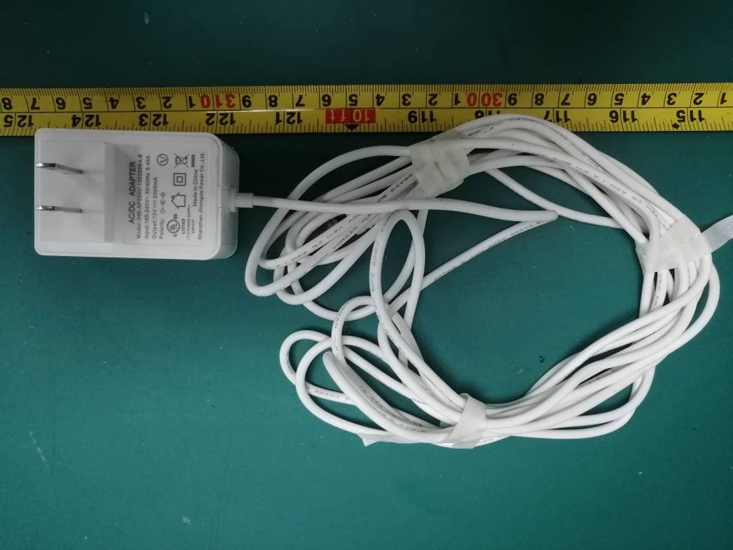
Click to zoom
Application Details
- Equipment Class
- DTS - Digital Transmission System
- Date of Grant
- May 09, 2021
- Application Purpose
- Original Equipment
- Date of Application
- May 09, 2021
- Equipment Note
- Camera
- Frequency Range
- 2412.00000000 - 2462.00000000
- Company
- SwamCam LLC.
- Country
- United States
Documents & Files
Document Text
Text extracted from the exhibit documents filed with the FCC. Open a document above to read the original.
Users Manual
FCC Caution: Any Changes or modifications not expressly approved by the party responsible for compliance could void the user's authority to operate the equipment. This device complies with part 15 of the FCC Rules. Operation is subject to the following two conditions: (1) This device may not cause harmful interference, and (2) this device must accept any interference received, including interference that may cause undesired operation. IMPORTANT NOTE: Note: This equipment has been tested and found to comply with the limits for a Class B digital device, pursuant to part 15 of the FCC Rules. These limits are designed to provide reasonable protection against harmful interference in a residential installation. This equipment generates, uses and can radiate radio frequency energy and, if not installed and used in accordance with the instructions, may cause harmful interference to radio communications. However, there is no guarantee that interference will not occur in a particular installation. If this equipment does cause harmful interference to radio or television reception, which can be determined by turning the equipment off and on, the user is encouraged to try to correct the interference by one or more of the following measures: —Reorient or relocate the receiving antenna. —Increase the separation between the equipment and receiver. —Connect the equipment into an outlet on a circuit different from that to which the receiver is connected. —Consult the dealer or an experienced radio/TV technician for help. FCC Radiation Exposure Statement: For repeater and camera: This equipment complies with FCC radiation exposure limits set forth for an uncontrolled environment. This equipment should be installed and operated with minimum distance 20cm between the radiator & your body. ManualV1R1_04/2021 For keypad: This equipment complies with FCC radiation exposure limits set forth for an uncontrolled environment. SwamCam User Manual The SwamCam camera system is an Artificial Intelligence swimming pool alarm designed to detect and warn as soon as a child enters the pool area. It has 3 components: 1. Camera 2. Wi-Fi repeater & siren 3. Keypad Quick Setup / Install 1. Download App 2. Sign up 3. If you have separate 2.4GHz and 5GHz wireless, place your phone on the 2.4GHz wireless network 4. Connect DC adapter to the Camera then plug camera into an outlet near the router and add to App 5. Plug extender into an outlet near the router and add to App 6. Insert batteries into the keypad and add to App 7. Install the camera at the pool 8. Plug in extender at desired location preferably inside the house in outlet closest to the pool 9. Check the App to make sure the camera has good reception and if not move the extender to a better location. Please allow the camera to settle on the best Wi-Fi connection before moving the extender (this may take up to a few hours). Lastly, enjoy the extra safety and peace of mind provided by your new SwamCam. u SwamCam Mounting Options...(cont.) Note: You may separate the camera mount in the center for easier installation. 1. To Mount the Camera a. For Chain-Link, Aluminum and Metal Fences Secure the Camera Mount (#3) to the mounting surface (fence) by placing the Camera Mount on the side facing the pool and the Round Plate (#4) on the opposite side of the fence. Use the bolts and nuts provided to secure and tighten. If desired, place the plastic caps on the exposed ends of the bolts. b. For PVC and Wood Fences and all types of Siding, secure the Camera Mount (#3) to the mounting surface by using the screws provided and attaching directly to the surface. 2. Mount the SwamCam Camera onto the Camera Mount by first screwing in the top part of the Camera Mount into the back of the SwamCam Camera and tighten the plastic ring. Then reattach the top part of the Camera Mount to the bottom. 3. Use the provided zip ties and cable tacks to secure the power cord. Be careful not to damage the power cord during installation. Top Part Bottom Part Note: The content of this manual is subject to change as we are constantly improving our products, updating the firmware on the camera and updating the App. Please see www.theswamcam.com for the latest information. 33 #4 Round plate for Camera mount #3 Camera Mount Bracket u SwamCam Mounting Options...(cont.) 1. To mount the Keypad a. For Chain-Link, Aluminum and Metal Fencing, secure the Back Plate (#1) to the mounting surface by placing the Back Plate on the side you want the keypad and Bolt Plate (#2) on the opposite side of the gate. Use the bolts and nuts provided to secure and tighten. If desired, place the plastic caps on the exposed ends of the bolts. b. For PVC and wood fences as well as all types of house siding, secure the Back Plate (#1) directly to the mounting surface using the screws provided and tighten (Bolt Plate #2 is not needed). 2. Mount the Keypad onto the Back Plate (#1) by placing the back prongs into back of Keypad first, then the bottom prongs into Keypad. Attach Keypad through 2 holes under Keypad by using the mini screws and screw driver provided. Table of Contents Registering a SwamCam Account 2 System Setup iOS 4 System Setup Android 6 Adding the Alarm/Repeater and Keypad 11 Live View 12 Keypad Functions 14 Resetting the Access Code 14 Using the Keypad 16 Using the Alarm 17 Using the Alarm as a Wi-Fi repeater 17 Controlling System Sounds 19 Motion Settings 20 Quiet Hours Settings 22 Sharing Access to your SwamCam 23 Premium Subscription features 25 Custom Alarm 26 Custom Emergency Dial 27 Live Recording 27 Rename or Delete SwamCam 28 Mobile App password reset 29 Resetting SwamCam Hardware 30 Mounting Options 31 #1 Back Plate for Keypad #2 Bolt Plate for Keypad mount 32 u Registering a SwamCam Account 1. Download the app from Apple App Store or Google Play Store by searching “SwamCam”. 2. Register an account by tapping “Register”. 3. Enter your name and mobile. 4. Enter your email address to register an account. You must pr…
Text truncated - open the document above for the full version.
Attestation Statements
SwamCam LLC. ADD: 400 Rella Blvd, Ste 123-115, Montebello, New York 10901, United States Tel: 914-246-0165 E-mail: [email protected] Date: 2021-04-26 FEDERAL COMMUNICATIONS COMMISSIONS Authorization and Evaluation Division 7435 Oakland Mills Road Columbia, MD 21046 Attestation letter Dear Sir or Madam, The RF Chip, model MT6737, which installed in our product camera, Model: SCCAM1, FCC ID: 2AYO8-SCCAM1, supports GSM,WCDMA,LTE,2.4G Wi-Fi,5G Wi-Fi,BT4.0 LE,GPS function. For use in the US market, this Chip only support 2.4G Wi-Fi, the other GSM,WCDMA,LTE, 5G Wi-Fi,BT4.0 LE,GPS function was disabled by the manufacturer in the software. The end user has no capability to activate it. Sincerely, Signature Ari Rolnick Title: Project Manager
Cover Letter(s)
SwamCam LLC. ADD: 400 Rella Blvd, Ste 123-115, Montebello, New York 10901, United States Tel: 914-246-0165 E-mail: [email protected] FCC Confidential Authorization Date: 2021-04-28 FEDERAL COMMUNICATIONS COMMISSIONS Authorization and Evaluation Division 7435 Oakland Mills Road Columbia, MD 21046 Subject: Confidentiality Request regarding application for certification of FCC ID: 2AYO8-SCCAM1 In accordance with Sections 0.457 and 0.459 of the Commission’s Rules, SwamCam LLC. hereby requests long-term confidential treatment of information accompanying this application as outlined below: Block Diagram Schematics Operation Description As well as short-term confidential treatment of information accompanying this application for a period of 180 days after grant is issued as outlined below: User’s Manual The above materials contain proprietary and confidential information not customarily released to the public. The public disclosure of these materials provides unjustified benefits to its competitors in the market. Sincerely Yours, Signature Contact person: Ari Rolnick Title: Project Manager
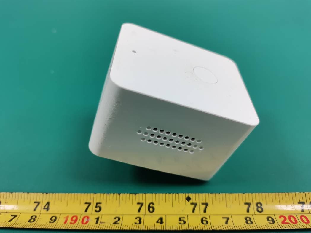
External Photos
Bay Area Compliance Laboratories Corp. (Shenzhen) Project No.: SZ1210201-03805E-RF Page 1 of 5 EXHIBIT B - EUT EXTERNAL PHOTOGRAPHS Bay Area Compliance Laboratories Corp. (Shenzhen) Project No.: SZ1210201-03805E-RF Page 2 of 5 Bay Area Compliance Laboratories Corp. (Shenzhen) Project No.: SZ1210201-03805E-RF Page 3 of 5 Bay Area Compliance Laboratories Corp. (Shenzhen) Project No.: SZ1210201-03805E-RF Page 4 of 5 Bay Area Compliance Laboratories Corp. (Shenzhen) Project No.: SZ1210201-03805E-RF Page 5 of 5
ID Label/Location Info
Bay Area Compliance Laboratories Corp. (Shenzhen) Project No.: SZ1210201-03805E-RF EXHIBIT A - FCC ID LABEL AND LOCATION FCC ID Label FCC ID Label Location Information The label shown shall be permanently affixed at a conspicuous location on the device and be readily visible to the user at the time purchase (Labeling requirements per 2.925)
Internal Photos
Bay Area Compliance Laboratories Corp. (Shenzhen) Project No.: SZ1210201-03805E-RF Page 1 of 7 EXHIBIT C - EUT INTERNAL PHOTOGRAPHS Bay Area Compliance Laboratories Corp. (Shenzhen) Project No.: SZ1210201-03805E-RF Page 2 of 7 Bay Area Compliance Laboratories Corp. (Shenzhen) Project No.: SZ1210201-03805E-RF Page 3 of 7 Bay Area Compliance Laboratories Corp. (Shenzhen) Project No.: SZ1210201-03805E-RF Page 4 of 7 Bay Area Compliance Laboratories Corp. (Shenzhen) Project No.: SZ1210201-03805E-RF Page 5 of 7 Bay Area Compliance Laboratories Corp. (Shenzhen) Project No.: SZ1210201-03805E-RF Page 6 of 7 Antenna-WIFI&ZIGBEE Bay Area Compliance Laboratories Corp. (Shenzhen) Project No.: SZ1210201-03805E-RF Page 7 of 7
RF Exposure Info
Bay Area Compliance Laboratories Corp. (Shenzhen) Report No.: SZ1210201-03805E-00 FCC Part 15.247 Page 12 of 66 FCC §15.247 (i) & §2.1091- MAXIMUM PERMISSIBLE EXPOSURE (MPE) Applicable Standard According to subpart 15.247 (i) and subpart 2.1091 systems operating under the provisions of this section shall be operated in a manner that ensures the public is not exposed to RF energy level in excess of the communication guidelines. Limits for General Population/Uncontrolled Exposure Limits for General Population/Uncontrolled Exposure Frequency Range (MHz) Electric Field Strength (V/m) Magnetic Field Strength (A/m) Power Density (mW/cm 2 ) Averaging Time (Minutes) 0.3-1.34 614 1.63 *(100) 30 1.34-30 824/f 2.19/f *(180/f 2 ) 30 30-300 27.5 0.073 0.2 30 300-1500 / / f/1500 30 1500-100,000 / / 1.0 30 f = frequency in MHz * = Plane-wave equivalent power density Result Calculated Formulary: Predication of MPE limit at a given distance S = 2 4R PG π S = power density (in appropriate units, e.g. mW/cm 2 ) P = power input to the antenna (in appropriate units, e.g., mW). G = power gain of the antenna in the direction of interest relative to an isotropic radiator, the power gain factor, is normally numeric gain. R = distance to the center of radiation of the antenna (appropriate units, e.g., cm) Bay Area Compliance Laboratories Corp. (Shenzhen) Report No.: SZ1210201-03805E-00 FCC Part 15.247 Page 13 of 66 Mode Frequency (MHz) Antenna Gain Max Tune-up Conducted Power Evaluation Distance (cm) Power Density (mW/cm 2 ) MPE Limit (mW/cm 2 ) (dBi) (numeric) (dBm) (mW) ZigBee 2405-2480 3.0 2.0 5.53.55200.0014 1 Wi-Fi 2412-2462 3.0 2.0 16.039.81200.016 1 Note: 1. the tune up conducted power was declared by the applicant 2. the Wi-Fi can transmit at the same time with the Zigbee. Simultaneous transmitting consideration: The ratio=MPE Wi-Fi /limit+MPE ZigBee /limit=0.0014+0.016=0.0174<1.0 To maintain compliance with the FCC’s RF exposure guidelines, place the equipment at least 20cm from nearby persons. Result: Compliance
Test Report
Note: This report may contain data that are not covered by the A2LA accreditation and are marked with an asterisk “★”. BACL is not responsible for the authenticity of any test data provided by the applicant. Data included from the applicant that may affect test results are marked with an asterisk ’*’. Customer model name, addresses, names, trademarks etc. are not considered data. This report cannot be reproduced except in full, without prior written approval of the Company. Unless otherwise stated the results shown in this test report refer only to the sample(s) tested. This report is valid only with a valid digital signature. The digital signature may be available only under the Adobe software above version 7.0. FCC PART 15.247 TEST REPORT For Swamcam LLC. 400 Rella Blvd, Ste 123-115, Montebello, New York 10901, United States FCC ID: 2AYO8-SCCAM1 Report Type: Original Report Product Type: camera Re port Number: SZ1210201-03805E-00 Re port Date: 2021-04-16 Reviewed B y: Jacob Kong RF En gineer Prepared By: Bay Area Compliance Laboratories Corp. (Shenzhen) 5F(B-West) , 6F, 7F, the 3rd Phase of Wan Li Industrial Building D, Shihua Rd, FuTian Free Trade Zone, Shenzhen, China Tel: +86-755-33320018 Fax: +86-755-33320008 www.baclcorp.com.cn Bay Area Compliance Laboratories Corp. (Shenzhen) Report No.: SZ1210201-03805E-00 FCC Part 15.247 Page 2 of 66 TABLE OF CONTENTS GENERAL INFORMATION ....................................................................................................................................... 4 PRODUCT DESCRIPTION FOR EQUIPMENT UNDER TEST (EUT) ..................................................................................... 4 OBJECTIVE ................................................................................................................................................................... 4 TEST METHODOLOGY .................................................................................................................................................. 4 MEASUREMENT UNCERTAINTY .................................................................................................................................... 5 SYSTEM TEST CONFIGURATION .......................................................................................................................... 6 DESCRIPTION OF TEST CONFIGURATION ...................................................................................................................... 6 EQUIPMENT MODIFICATIONS ....................................................................................................................................... 6 EUT EXERCISE SOFTWARE .......................................................................................................................................... 7 DUTY CYCLE ................................................................................................................................................................ 7 SUPPORT EQUIPMENT LIST AND DETAILS .................................................................................................................... 8 EXTERNAL I/O CABLE .................................................................................................................................................. 8 BLOCK DIAGRAM OF TEST SETUP ................................................................................................................................ 8 SUMMARY OF TEST RESULTS ............................................................................................................................... 9 TEST EQUIPMENT LIST ......................................................................................................................................... 10 FCC §15.247 (i) & §2.1091- MAXIMUM PERMISSIBLE EXPOSURE (MPE) ........................................................ 12 APPLICABLE STANDARD ............................................................................................................................................ 12 RESULT ...................................................................................................................................................................... 12 FCC §15.203 - ANTENNA REQUIREMENT ........................................................................................................... 14 APPLICABLE STANDARD ............................................................................................................................................ 14 ANTENNA CONNECTOR CONSTRUCTION .................................................................................................................... 14 FCC §15.207 (a) – AC LINE CONDUCTED EMISSIONS ..................................................................................... 15 APPLICABLE STANDARD ............................................................................................................................................ 15 EUT SETUP ................................................................................................................................................................ 15 EMI TEST RECEIVER SETUP ....................................................................................................................................... 15 TEST PROCEDURE ...................................................................................................................................................... 15 CORRECTED FACTOR & MARGIN CALCULATION ....................................................................................................... 16 TEST DATA ................................................................................................................................................................ 16 FCC §15.209, §15.205 & §15.247(d) - SPURIOUS EMISSIONS ............................................................................. 19 APPLICABLE STANDARD ..............…
Text truncated - open the document above for the full version.
Test Setup Photos
Bay Area Compliance Laboratories Corp. (Shenzhen) Project No.: SZ1210201-03805E-RF EXHIBIT D - TEST SETUP PHOTOGRAPHS Conducted Emissions - Front View Conducted Emissions - Side View Bay Area Compliance Laboratories Corp. (Shenzhen) Project No.: SZ1210201-03805E-RF Radiated Emissions View (Below 1 GHz) Radiated Emissions View (Above 1 GHz)
Contact Information
Applicant
Ari Rolnick(Project Manager)
Test Firm
Bay Area Compliance Laboratories Corp. (Shenzhen)Well Wang
[email protected]+86 (0) 755 33320018
Technical Specifications
| # | Rule Parts | Frequency Range | Power Output |
|---|---|---|---|
| 2 | 15C | 2.41 GHz - 2.46 GHz | 37.00 mW |
Other Applications from SwamCam LLC.
2AYO8-SCRP1
May 09, 2021Repeater
Equipment Class
DTS - Digital Transmission System
2AYO8-SCKP1
May 09, 2021Keypad
Equipment Class
DTS - Digital Transmission System