2AYOO-TCB10001Ultra WideBand indoor position beacon
Geonavo Positioning Systems Inc.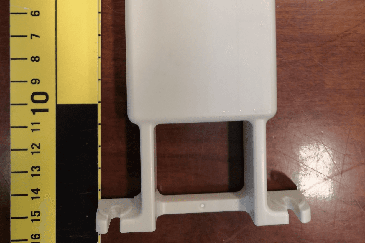
Click to zoom
Application Details
- Equipment Class
- WBT - Wideband Transmitter
- Date of Grant
- Mar 11, 2021
- Application Purpose
- Original Equipment
- Date of Application
- Mar 07, 2021
- Equipment Note
- Ultra WideBand indoor position beacon
- Frequency Range
- 6201.00000000 - 6769.00000000
- Country
- Canada
Documents & Files
Document Text
Text extracted from the exhibit documents filed with the FCC. Open a document above to read the original.
Users Manual
Hardware Guide Version 1.6 Feb, 2021 Installation Guide Tenera This material is the property of GeoNavo Positioning Systems, Inc. It may contain certain confidential and proprietary information and is not to be reproduced, distributed or otherwise disclosed to any third party without permission of GeoNavo Positioning Systems, Inc. All rights, including copyright and patent rights are reserved by GeoNavo Positioning Systems, Inc. © 2017 GeoNavo Positioning Systems, Inc. 1 TABLE OF CONTENTS Table of Contents 1.0 INTRODUCTION .......................................................................................................................... 2 1.2 PROVISIONING PROCEDURE ........................................................................................................ 6 1.3 INSTALLER CONSOLE PROCEDURE ............................................................................................. 9 1.4 BRACELET SPECIFICATIONS ..................................................................................................... 11 1.5 BEACON SPECIFICATIONS ......................................................................................................... 12 1.6 RF CERTIFICATION NOTICES .................................................................................................... 13 Beacon Information .................................................................................................... 13 Tag Information ........................................................................................................ 13 FCC Regulatory Statements ............................................................................................ 13 RF Exposure Warning (FCC) .......................................................................................... 13 ISED Regulatory Statements ........................................................................................... 14 RF Exposure Information (ISED) ..................................................................................... 14 Installation Guide Tenera This material is the property of GeoNavo Positioning Systems, Inc. It may contain certain confidential and proprietary information and is not to be reproduced, distributed or otherwise disclosed to any third party without permission of GeoNavo Positioning Systems, Inc. All rights, including copyright and patent rights are reserved by GeoNavo Positioning Systems, Inc. © 2017 GeoNavo Positioning Systems, Inc. 2 1.0 INTRODUCTION The Hardware Guide provides users with an overview of how to install and provision the Tenera Bracelet and Beacon. It outlines the hardware specifications Installation Guide Tenera This material is the property of GeoNavo Positioning Systems, Inc. It may contain certain confidential and proprietary information and is not to be reproduced, distributed or otherwise disclosed to any third party without permission of GeoNavo Positioning Systems, Inc. All rights, including copyright and patent rights are reserved by GeoNavo Positioning Systems, Inc. © 2017 GeoNavo Positioning Systems, Inc. 3 1.1 HARDWARE OVERVIEW The system is 100% designed and manufactured in Canada. In order to locate a resident, staff, visitor, contractor or asset the system triangulates the location utilizing Ultra- Wideband (UWB) radio technology. The system relies on 4 key pieces of technology in order to triangulate the X-Y-Z three-dimensional location and consists of the following: 1. Tenera Bracelet: The bracelet is a sleek and comfortable wearable that broadcast its location every second to the beacons. It uses IEEE802:15.4-2011 UWB technology for the highest accuracy positioning available. The bracelet is dust and water resistant with an IP67 rating. Rechargeable Lithium Ion batteries are used to make maintenance and recharging easy. The straps use standard 18mm mounting hardware and can be customized to suit the user with different color options and locking mechanisms. To turn the bracelet on, hold down the red button for 10 seconds. The button will then flash a light to confirm it’s on. To turn the bracelet off, hold down the red button for 10 seconds. If you push the red button and the led lights up, then you know the bracelet is turned on. If you push the red button and the led does not light up, then you know the bracelet is turned off. Installation Guide Tenera This material is the property of GeoNavo Positioning Systems, Inc. It may contain certain confidential and proprietary information and is not to be reproduced, distributed or otherwise disclosed to any third party without permission of GeoNavo Positioning Systems, Inc. All rights, including copyright and patent rights are reserved by GeoNavo Positioning Systems, Inc. © 2017 GeoNavo Positioning Systems, Inc. 4 2. Tenera Beacon: The beacons are strategically mounted in fixed positions around the facility during the initial installation. Their fixed location is loaded through the installer console (appendix F). The beacons listen for UWB transmissions from the bracelet and communicate with the cloud servers to perform real time localization. Positioning algorithms with a strong emphasis on multipath rejection and sophisticated modeling give high performance in difficult Non-Line of Sight (NLOS) environments. Installation Guide Tenera This material is the property of GeoNavo Positioning Systems, Inc. It may contain certain confidential and proprietary information and is not to be reproduced, distributed or otherwise disclosed to any third party without permission of GeoNavo Positioning Systems, Inc. All rights, including copyright and patent rights are reserved by GeoNavo Positioning Systems, Inc. © 2017 GeoNavo Positioning Systems, Inc. 5 3. Google WiFi Mesh Network: The Google WiFi Mesh network creates a private wireless network allowing the Tenera Platform to transfer the X-Y-Z position of each bracelet to the cloud servers for processing. The Mesh network provides more coverage than a traditional …
Text truncated - open the document above for the full version.
Cover Letter(s)
Geonavo Positioning Systems Inc. 1600 Bedford Highway, Unit 401 - Fourth Floor Bedford, Nova Scotia Canada, B4A 1E8 TUV SUD America Inc. 10 Centennial Drive Peabody, Massachusetts USA, 01960 February 3, 2021 To Whom It May Concern, We, Geonavo Positioning Systems Inc, 1600 Bedford Highway, Suite 401, Nova Scotia, B4A 1E8 Canada, hereby authorize Min Xie of TUV SUD Canada Inc., 11 Gordon Collins Dr. Gormley, L0H 1G0, Canada; 905-883-7255 to act as our agent in all matters relating to applications for equipment authorization, including the signing of all documents relating to these matters. This authorization expires on 9/1/2021. Kind Regards, Ioan Curticapean Hardware Development Lead Geonavo Positioning Systems Inc.
Cover Letter(s)
Geonavo Positioning Systems Inc. 1600 Bedford Highway, Unit 401 - Fourth Floor Bedford, Nova Scotia Canada, B4A 1E8 Federal Communications Commission — Equipment Authorization Branch 7435 Oakland Mills Road Columbia, MD USA, 21046 February 3, 2021 Confidentiality Request, FCC ID: 2AYOO-TCB10001 Pursuant to Sections 0.457(d)(1)(ii) and 0.459 of the Commission’s Rules, Geonavo Position- ing System Inc. hereby requests permanent confidential treatment of information accompa- nying this application as outlined below: •Schematics •Bill of Materials/Parts List •Block Diagrams •Theory of Operation The above materials contain trade secrets and proprietary information not customarily re- leased to the public. The public disclosure of these matters might be harmful to the Applicant and provide unjustified benefits to its competitors. The Applicant understands that pursuant to Rule 0.457(d)(1)(ii), disclosure of this Applica- tion and all accompanying materials will not be made before the date of the Grant for this Application. Kind Regards, Ioan Curticapean Hardware Development Lead Geonavo Positioning Systems Inc.
External Photos
Report File #: 7169007900RB-000 © TÜV SÜD Canada Inc. This test report shall not be reproduced except in full, without written approval of TÜV SÜD Canada Inc Exhibit: External Photos Client Geonavo Positioning Systems Inc. Product Tenera Beacon Page 2 of 3 Report Issued: 2/8/2021 Report File #: 71690067900RB-000 © TÜV SÜD Canada Inc. This test report shall not be reproduced except in full, without written approval of TÜV SÜD Canada Inc. Figure 1 – EUT External Photo Front Client Geonavo Positioning Systems Inc. Product Tenera Beacon Page 3 of 3 Report Issued: 2/8/2021 Report File #: 71690067900RB-000 © TÜV SÜD Canada Inc. This test report shall not be reproduced except in full, without written approval of TÜV SÜD Canada Inc. Figure 2 – EUT External Photo Back
ID Label/Location Info
Report File #: 7169007900RB-000 © TÜV SÜD Canada Inc. This test report shall not be reproduced except in full, without written approval of TÜV SÜD Canada Inc. Exhibit: Label and Label Location Client GeoNavo Positioning Systems Inc. Product Tenera Beacon Page 2 of 3 Report Issued: 3/5/2021 Report File #: 7169007900RB-000 © TÜV SÜD Canada Inc. This test report shall not be reproduced except in full, without written approval of TÜV SÜD Canada Inc. Client GeoNavo Positioning Systems Inc. Product Tenera Beacon Page 3 of 3 Report Issued: 3/5/2021 Report File #: 7169007900RB-000 © TÜV SÜD Canada Inc. This test report shall not be reproduced except in full, without written approval of TÜV SÜD Canada Inc. Label Location
Internal Photos
Report File #: 7169007900RB-000 © TÜV SÜD Canada Inc. This test report shall not be reproduced except in full, without written approval of TÜV SÜD Canada Inc Exhibit: Internal Photos Client Geonavo Positioning Systems Inc. Product Tenera Beacon Page 2 of 3 Report Issued: 2/8/2021 Report File #: 71690067900RB-000 © TÜV SÜD Canada Inc. This test report shall not be reproduced except in full, without written approval of TÜV SÜD Canada Inc. Figure 1 – EUT Internal Photo Front Client Geonavo Positioning Systems Inc. Product Tenera Beacon Page 3 of 3 Report Issued: 2/8/2021 Report File #: 71690067900RB-000 © TÜV SÜD Canada Inc. This test report shall not be reproduced except in full, without written approval of TÜV SÜD Canada Inc. Figure 2 – EUT Internal Photo Back
RF Exposure Info
Report File #:7169007900RB-000 © TÜV SÜD Canada Inc. This test report shall not be reproduced except in full, without written approval of TÜV SÜD Canada Inc Exhibit: RF Exposure – FCC Client Geonavo Positioning Systems Inc. Product Tenera Beacon Page 2 of 3 Report Issued: 2/8/2021 Report File #: 7169007900RB-000 © TÜV SÜD Canada Inc. This test report shall not be reproduced except in full, without written approval of TÜV SÜD Canada Inc. RF Exposure – FCC The device is a mobile device intended to generally be used in such a way that a separation distance of at least 20 centimeters is normally maintained between the transmitter's radiating structure and the body of the user or nearby persons. The EUT contains a 6. MHz FHSS transmitter and a 2400 – 2483.5 MHz DTS transmitter. Radiofrequency Radiation Exposure Evaluation: Mobile Devices Mobile devices shall be evaluated for RF radiation exposure according to the provisions of FCC §2.1091 and the MPE guidelines identified in FCC §1.1310. As per FCC §1.1310 Table 1(B), the limit for Maximum Permissible Exposure (MPE) to radiofrequency electromagnetic fields for General Population/Uncontrolled Exposure in the frequency range of 300 MHz to 1.5 GHz is f/1500 mW/cm 2 and in the frequency range of 1.5GHz to 100GHz is 1.0 mW/cm 2 . Where f = frequency in MHz. The power density formula is given by: P d = (P out *G) / (4*pi*R 2 ) Where, P d = Power density in mW/cm 2 P out = Conducted output power to antenna in mW G = Numeric Antenna Gain Pi = 3.1416 R = Separation distance in cm The term (P out *G) is the E.I.R.P of the transmitter. MPE Calculation: 6.5 GHz UWB transmitter The UWB transmitter has an E.I.R.P of -1.9 dBm or 0.65 mW. For a separations distance of 20 cm, the power density is: P d = (0.65 mW) / (4 * 3.1416 * (20cm) 2 ) P d = 0.00013 mW/cm 2 The device passes the requirement. The calculated power density of 0.00013 mW/cm 2 is below the 1 mW/cm 2 limit. Client Geonavo Positioning Systems Inc. Product Tenera Beacon Page 3 of 3 Report Issued: 2/8/2021 Report File #: 7169007900RB-000 © TÜV SÜD Canada Inc. This test report shall not be reproduced except in full, without written approval of TÜV SÜD Canada Inc. Simultaneous Transmission For simultaneous transmission, the Sum of rations of MPEs shall be < 1. The device integrates a 2.4 GHz DTS modular transmitter with possible simultaneous transmission. The sum of MPE ratios reported is 0.031. ∑ of MPE rations = MPE of UWB + ∑ MPE of module = 0.00013 + 0.031 = 0. 03113 < 1 The device meets simultaneous transmission requirement.
Test Report
Registration # 6844A-3 Testing Laboratory Certificate #2955.02 R-14023, G-20072 C-14498, T-20060 Registration # CA6844 Page 1 of 56 Report Issued: 3/5/2021 Report File #: 7169007900RA-001 © TÜV SÜD Canada Inc. This test report shall not be reproduced except in full, without written approval of TÜV SÜD Canada Inc. FCC_KDB_ICES003_Emissions_Rev1 EMC Test Report As per FCC Part 15 Subpart 15.250 Unlicensed Intentional Radiator on the Tenera Beacon Issued by: TÜV SÜD Canada Inc. 11 Gordon Collins Dr, Gormley, ON, L0H 1G0 Canada Ph: (905) 883-7255 Testing produced for See Appendix A for full client & EUT details. Prepared by: Min Xie, Sr. EMCEngineer Reviewed by: Scott Drysdale, Wireless Manager Client GeoNavo Positioning Systems Inc. Product Tenera Beacon Standard(s) FCC Part 15 Subpart 15.250 Page 2 of 56 Report Issued: 3/5/2021 Report File #: 7169007900RA -001 © TÜV SÜD Canada Inc. This test report shall not be reproduced except in full, without written approval of TÜV SÜD Canada Inc. Table of Contents Table of Contents ................................................................................................................... 2 Report Scope .......................................................................................................................... 3 Summary ................................................................................................................................ 4 Test Results Summary ....................................................................................................... 5 Notes, Justifications, or Deviations ................................................................................... 6 Sample Calculation(s) ........................................................................................................ 7 Applicable Standards, Specifications and Methods ............................................................... 8 Document Revision Status ..................................................................................................... 9 Definitions and Acronyms ................................................................................................... 10 Testing Facility .................................................................................................................... 11 Calibrations and Accreditations ....................................................................................... 11 Testing Environmental Conditions and Dates ................................................................. 12 Detailed Test Result Section ................................................................................................ 13 Temperature Frequency Stability ..................................................................................... 14 10 Bandwidth ................................................................................................................... 16 Transmitter Spurious Radiated Emissions ....................................................................... 19 Output Power ................................................................................................................... 40 Power Line Conducted Emissions ................................................................................... 47 Appendix A – EUT & Client Provided Details ................................................................... 53 Appendix B – EUT, Peripherals, and Test Setup Photos ..................................................... 56 Client GeoNavo Positioning Systems Inc. Product Tenera Beacon Standard(s) FCC Part 15 Subpart 15.250 Page 3 of 56 Report Issued: 3/5/2021 Report File #: 7169007900RA -001 © TÜV SÜD Canada Inc. This test report shall not be reproduced except in full, without written approval of TÜV SÜD Canada Inc. Report Scope This report addresses the EMC verification testing and test results of the Tenera Beacon, herein referred to as EUT (Equipment Under Test). The EUT was tested for emissions compliance against the following standards: FCC Part 15 Subpart 15.250 Test procedures, results, justifications, and engineering considerations, if any, follow later in this report. The results contained in this report relate only to the item(s) tested. This report does not imply product endorsement by any government, accreditation agency, or TÜV SÜD Canada Inc. Opinions or interpretations expressed in this report, if any, are outside the scope of TÜV SÜD Canada Inc. accreditations. Any opinions expressed do not necessarily reflect the opinions of TÜV SÜD Canada Inc., unless otherwise stated. Client GeoNavo Positioning Systems Inc. Product Tenera Beacon Standard(s) FCC Part 15 Subpart 15.250 Page 4 of 56 Report Issued: 3/5/2021 Report File #: 7169007900RA -001 © TÜV SÜD Canada Inc. This test report shall not be reproduced except in full, without written approval of TÜV SÜD Canada Inc. Summary The results contained in this report relate only to the item(s) tested. EUT: Tenera Beacon FCC Certification #, FCC ID: 2AYOO-TCB10001 EUT passed all tests performed Yes Tests conducted by Min Xie For testing dates, see 'Testing Environmental Conditions and Dates'. Client GeoNavo Positioning Systems Inc. Product Tenera Beacon Standard(s) FCC Part 15 Subpart 15.250 Page 5 of 56 Report Issued: 3/5/2021 Report File #: 7169007900RA -001 © TÜV SÜD Canada Inc. This test report shall not be reproduced except in full, without written approval of TÜV SÜD Canada Inc. Test Results Summary Standard/Method Description Class/Limit Result FCC 15.203 Antenna Requirement Unique Pass See Justification FCC 15.207 Power line conducted emissions QuasiPeak Average Pass FCC 15.250 (a) 10 dB Bandwidth / Frequency Stability Within 5920 – 7250 MHz Band Pass FCC 15.250 (b) 10 dB Bandwidth > 50 MHz Pass 15.250 (d) (4)/ FCC 15.209 Radiated emissions below 960 MHz QuasiPeakPass FCC 15.250 (d) (1) Radiated Emission above 960 MHz RMS Average 1 MHz Bandwidth Pass FCC 15.250 (d) (3) Peak Power in 50 MHz …
Text truncated - open the document above for the full version.
Test Setup Photos
Report File #: 7169007900RB-000 © TÜV SÜD Canada Inc. This test report shall not be reproduced except in full, without written approval of TÜV SÜD Canada Inc Exhibit: Test Setup Photos Client Geonavo Positioning Systems Inc. Product Tenera Beacon Page 2 of 6 Report Issued: 2/8/2021 Report File #: 7169007900RB-000 © TÜV SÜD Canada Inc. This test report shall not be reproduced except in full, without written approval of TÜV SÜD Canada Inc. Figure 1 ‒ Radiated Emissions Setup – Photo 1 Client Geonavo Positioning Systems Inc. Product Tenera Beacon Page 3 of 6 Report Issued: 2/8/2021 Report File #: 7169007900RB-000 © TÜV SÜD Canada Inc. This test report shall not be reproduced except in full, without written approval of TÜV SÜD Canada Inc. Figure 2 ‒ Radiated Emissions Setup – Photo 2 Note: As per ANSI C63.10-2013 Clause 6.3.1, below 1GHz, the height of the EUT was set to 80cm. Above 1GHz, the height was raised to 1.5m. Client Geonavo Positioning Systems Inc. Product Tenera Beacon Page 4 of 6 Report Issued: 2/8/2021 Report File #: 7169007900RB-000 © TÜV SÜD Canada Inc. This test report shall not be reproduced except in full, without written approval of TÜV SÜD Canada Inc. Figure 3 ‒ Radiated Emissions Setup – Photo 3 Note: As per ANSI C63.10-2013 Clause 6.3.1, above 1GHz, the height of the EUT was set to 1.5m. Client Geonavo Positioning Systems Inc. Product Tenera Beacon Page 5 of 6 Report Issued: 2/8/2021 Report File #: 7169007900RB-000 © TÜV SÜD Canada Inc. This test report shall not be reproduced except in full, without written approval of TÜV SÜD Canada Inc. Figure 4 ‒ Radiated Emissions Setup– Photo 4 Note: As per ANSI C63.10-2013 Clause 6.3.1, above 1GHz, the height of the EUT was set to 1.5m. Client Geonavo Positioning Systems Inc. Product Tenera Beacon Page 6 of 6 Report Issued: 2/8/2021 Report File #: 7169007900RB-000 © TÜV SÜD Canada Inc. This test report shall not be reproduced except in full, without written approval of TÜV SÜD Canada Inc. Figure 5 ‒ Frequency Stability Setup
Contact Information
Applicant
Malcolm Williams(Localization Lead)
Test Firm
TUV SUD CANADA (Gormley)William (Mac) Elliott
[email protected]813-284-2736
Technical Specifications
| # | Rule Parts | Frequency Range | Power Output |
|---|---|---|---|
| 1 | 15.250 | 6.20 GHz - 6.77 GHz | - |