2AYSO-F803-0049NFC BOARD
Cubicon. INC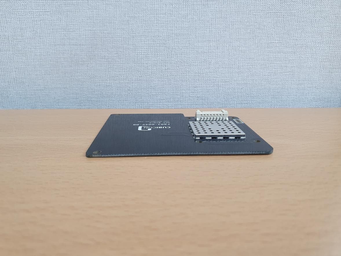
Click to zoom
Application Details
- Equipment Class
- DXX - Part 15 Low Power Communication Device Transmitter
- Date of Grant
- Feb 10, 2021
- Application Purpose
- Original Equipment
- Date of Application
- Feb 10, 2021
- Equipment Note
- NFC BOARD
- Frequency Range
- 13.56000000 - 13.56000000
- Company
- Cubicon. INC
- Country
- South Korea
Documents & Files
Document Text
Text extracted from the exhibit documents filed with the FCC. Open a document above to read the original.
Users Manual
Page 1 / 7 www.3dcubicon.com NFC Board Manual (F803-0049 Series) Features ■ Operating modes supported: – Reader/Writer ■ Hardware features – Dedicated internal frame controller – Highly integrated Analog Front End (AFE) for RF communications – Transmission and reception modes – Optimized power management – Tag Detection modes ■ RF communication @13.56 MHz – ISO/IEC 14443 A and B – ISO/IEC 15693 – ISO/IEC 18092 ■ Communication interfaces with a Host Controller – Serial peripheral interface (SPI) Slave interface – Connector : SMAW200-08 (YEONHO) Page 2 / 7 www.3dcubicon.com Description The F803-0049 is an integrated transceiver IC for contactless applications. The F803-0049 manages the frame coding and decoding in Reader mode for standard applications such as NFC, proximity and vicinity standards. The F803-0049 embeds the Analog Front End for 13.56 MHz Air Interface. The F803-0049 supports ISO/IEC 14443 A and B, ISO/IEC 15693 (single or double subcarrier) and ISO/IEC 18092 protocols. Figure1. F803-0049 application overview Table1. F803-0049 Connection Pin Map SMAW200-08 Pin Number Signal Name 1 nSPI_SS 2 SPI_MISO 3 SPI_MOSI 4 SPI_SCK 5 nIRQ_IN 6 Detect_TAG 7 VCC 8 GND Page 3 / 7 www.3dcubicon.com Commands Command format Fields <Cmd>, <RespCode> and <Len> are always 1 byte long. <Data> can be from 0 to 255 bytes. ● Direction: MCU to F803-0049 <CMD><Len><Data> ● Direction: F803-0049 to MCU <RespCode><Len><Data> Note: EchoCode is an exception as it has only one byte (0x55). List of commands Table2 lists the command set available for standard use. Table 2. List of commands Code Command Description 01 IDN Requests short information about F803-0049 and its firmware version. 02 Protocol Select Select communication protocol and specify some protocol-related parameters. 04 SendRecv Sends data using previously selected protocol and receives the tag response. 07 Idle Switches the F803-0049 into TagDetect or Hibernate state and specifies under which condition to exit from these states. 08 RdReg Reads wakeup flags. 0A BaudRate Sets UART baud rate. 55 EchoCode Performs a serial interface echo. Other codes Reserved Page 4 / 7 www.3dcubicon.com Operating modes The F803-0049 has 2 operating modes: Idle and Active. In Active mode, the F803-0049 communicates actively with a tag or an external MCU. Idle mode includes two low consumption states: Hibernate and Tag Detector. The F803-0049 can switch from one mode to another. Table 3. Operating modes Mode State Description Idle Hibernate Lowest power consumption. F803-0049 has to be waken-up in order to communicate. Low level on nIRQ_IN pin is the only wakeup source. Tag Detector Low power consumption, Tag detection. Wakeup source is configurable: – Timer – nIRQ_IN pin – nSPI_SS pin – Tag detector LFO (low-frequency oscillator) is running in this state. Active Standby or Reader Main communication mode. HFO (high- frequency oscillator) is running, F803-0049 is able to decode and execute commands from external MCU. It can switch the reader ON and OFF and communicate with a tag or an external MCU. Hibernate and Tag-Detector states can only be activated by a command from the external MCU. As soon as Application environmentany of these states are activated, the F803-0049 can no longer communicate with the external MCU. It can only be woken up. The behavior of the F803-0049 in 'Tag-Detector' state is defined by the Idle command. Page 5 / 7 www.3dcubicon.com Electrical characteristics Absolute maximum ratings Table 4. Absolute maximum ratings Parameter Value Unit Supply Voltage (VCC to GND) 5.5 V Input or Output voltage relative to Ground 3.0 ± 0.3 V Ambient operating temperature -25 to +85 °C Ambient operating temperature (RF mode) -25 to +85 °C Storage temperature -25 to +85 °C Note: Stresses listed above may cause permanent damage to the device. This is a stress rating only and functional operation of the device at these or any other conditions above those indicated in the operational sections of the specification is not implied. Exposure to absolute maximum rating conditions for extended periods may affect device reliability. Product Certification Information Product Name : NFC BOARD Model Name : F803-0049 FCC ID : 2AYSO-F803-0049 KC : R-R-CU5-F803-0049 Rated : DC 5V Cubicon Inc. Made in Korea Page 6 / 7 www.3dcubicon.com ▣ CE statement This device can be operated in at least one Member State without infringing applicable requirements on the use of radio spectrum." - RF Range: 13.56MHz (RFID) ▣ FCC statement Certification and Safety Approvals FCC Compliance Statement This device complies with part 15 of the FCC rules. Operation is subject to the following two conditions: (1) This device may not cause harmful interference, and (2) This device must accept any interference received, including interference that may cause undesired operation. changes or modifications not expressly approved by the party responsible for compliance could void the user’s authority to operate the equipment. This equipment has been tested and found to comply with the limits for a Class B digital device pursuant to part 15 of the FCC rules. These limits are designed to provide reasonable protection against harmful interference in a residential installation. This equipment generates, uses and can radiate radio frequency energy and, if not installed and used in accordance with the instructions, may cause harmful interference to radio communications. However, there is no guarantee that interference will not occur in a particular installation. If this equipment does cause harmful interference to radio or television reception, which can be determined by turning the equipment on and off, the user is encouraged to try to correct the interference by one or more of the following measures: -Reorient or relocate the receiving antennae -Increase the separation between the equipment and the receiver -Connect the equipment into an outlet on a circuit different from that to which the receiver is connected. -C…
Text truncated - open the document above for the full version.
Cover Letter(s)
Cubicon. INC Jan 27, 2021 Timco Engineering, Inc. 849 N.W. State Road 45 P.O. Box 370a Newberry, Florida 32669 USA Letter of Authorization We, the undersigned, hereby authorize Kenneth Kim of NCT Co.,Ltd. to act on our behalf in all manners relating to application for equipment authorization for FCC ID: 2AYSO-F803-0049 including signing of all documents relating to these matters. Any and all acts carried out by Kenneth Kim of NCT Co.,Ltd. on our behalf shall have the same affect as acts of our own. This authorization is valid until further written notice from Cubicon. INC “I, the undersigned, hereby certify that we are not subject to a denial of federal benefits, that includes FCC benefits, pursuant to Section 5301 of the Anti-Drug Abuse Act of 1988, 21 U.S.C. 853(a).” Sincerely, Hyunho Park / Product Design Team Cubicon. INC
Cover Letter(s)
Cubicon. INC Federal Communications Commission Authorization and Evaluation Division Confidentiality Request regarding application for certification of FCC ID: 2AYSO-F803-0049 Pursuant to Sections 0.457 and 0.459 of the Commission’s Rules, we hereby request confidential treatment of information accompanying this application as outlined below: Exhibit Type File Name Block Diagram Schematics Operational Description Part List [F803-0049] BLK [F803-0049] SCH [F803-0049] OpDes [F803-0049] Part List The above materials contain trade secrets and proprietary information not customarily released to the public. The public disclosure of these materials may be harmful to the applicant and provide unjustified benefits to its competitors. The applicant understands that pursuant to Section 0.457 of the Rules, disclosure of this application and all accompanying documentation will not be made before the date of the Grant for this application. In additional to above mentioned documents, in order to comply with the marketing regulations in Title 47 CFR §2.803 and the importation rules in Title 47 CFR §2.1204, while ensuring that business sensitive information remains confidential until the actual marketing of newly authorized devices, we request Short Term Confidentiality of the following attachment(s); Exhibit Type File Name External Photos Internal Photos Test Setup Photos Manual [F803-0049] EXT Photo [F803-0049] INT Photo [F803-0049] Test Setup Photo [F803-0049] Manual For 45 days, pursuant to Public Notice DA 04-1705. OR For 180 days pursuant to KDB 726920 D01. Sincerely, Hyunho Park / Product Design Team Cubicon. INC
Cover Letter(s)
Cubicon. INC Jan 27, 2021 Modular Approval Request Letter Applicant: Cubicon. INC FCC ID: 2AYSO-F803-0049 Item Modular requirement Yes No 1 The radio elements must have the radio frequency circuitry shielded. Physical components and tuning capacitor(s) may be located external to the shield, but must be on the module assembly; Yes 2 The module must have buffered modulation/data inputs to ensure that the device will comply with Part 15 requirements with any type of input signal; Yes 3 The module must contain power supply regulation on the module; Yes 4 The module must contain a permanently attached antenna, or contain a unique antenna connector, and be marketed and operated only with specific antenna(s), per Sections 15.203, 15.204(b), 15.204(c), 15.212(a), 2.929(b); Yes 5 The module must demonstrate compliance in a stand-alone configuration; Yes 6 The module must be labelled with its permanently affixed FCC ID label, or use an electronic display (See KDB Publication 784748 about labelling requirements); Yes 7 The module must comply with all specific rules applicable to the transmitter including all the conditions provided in the integration instructions by the grantee; Yes 8 The module must comply with RF exposure requirements Yes Sincerely, Hyunho Park / Product Design Team Cubicon. INC
ID Label/Location Info
Label & Location
Internal Photos
Antenna
Test Report
Test Repot No.: NW2101-F003-1 211-71, Geumgok-ro, Hwaseong-si, Gyeonggi-do, Korea 18511 www.nct.re.kr TEL: +82-31-323-6070 FAX: +82-31-323-6071 Page 2 of 22 Table of contents 1. General Information -------------------------------------------------------------------------------- 2. Information’s about Test Item ------------------------------------------------------------------- 3. Test Report -------------------------------------------------------------------------------------------- 3.1 Test Summary ------------------------------------------------------------------------------------- 3.2 Test Report Version ----------------------------------------------------------------------------- 3.3 Transmitter Requirements 3.3.1 Antenna Requirement --------------------------------------------------------------------- 3.3.2 20 ㏈ Bandwidth --------------------------------------------------------------------------- 3.3.3 In-Band Emissions ------------------------------------------------------------------------- 3.3.4 Out-of-Band Emissions ------------------------------------------------------------------- 3.3.5 Frequency Stability ------------------------------------------------------------------------- 3.3.6 Conducted Emission ----------------------------------------------------------------------- APPENDIX APPENDIX I TEST SETUP ---------------------------------------------------------------------- APPENDIX II TEST EQUIPMENT USED FOR TESTS ---------------------------------- 3 3 5 5 6 7 8 9 12 15 16 19 21 Test Repot No.: NW2101-F003-1 211-71, Geumgok-ro, Hwaseong-si, Gyeonggi-do, Korea 18511 www.nct.re.kr TEL: +82-31-323-6070 FAX: +82-31-323-6071 Page 3 of 22 1. General Information’s 1.1 Test Performed Laboratory : NCT Co., Ltd. Address : 211-71, Geumgok-ro, Hwaseong-si, Gyeonggi-do, 18511, Korea Telephone : +82-31-323-6070 Facsimile : +82-31-323-6071 FCC Designation No. : KR0166 FCC Registration Number : 409631 2. Information’s about Test Item 2.1 Applicant Information Company name : Cubicon. INC Address : 527, Dunchon-daero, Jungwon-gu, Seongnam-si, Gyeonggi-do, 13216 Republic of Korea Telephone / Facsimile : +82-1661-4371 / +82-070-8228-4966 2.2 Equipment Under Test (EUT) description Test item particulars : NFC BOARD Model and/or type reference : F803-0049 Additional model name : - Serial number : Identification Antenna type and gain : PCB Pattern Antenna Date (s) of performance of tests: : 2021-01-13 ~ 2021-02-09 Date of receipt of test item : 2020-12-17 EUT condition : Pre-production, not damaged Number of channel : 1 EUT Power Source : DC 5.0 V Type of Modulation : ASK Fir㎽are version : 1.0 Hardware version : 1.0 Test software name(version) : - Test Repot No.: NW2101-F003-1 211-71, Geumgok-ro, Hwaseong-si, Gyeonggi-do, Korea 18511 www.nct.re.kr TEL: +82-31-323-6070 FAX: +82-31-323-6071 Page 4 of 22 2.3 Tested Frequency Test Mode Test frequency (㎒) RFID 13.56 Test Repot No.: NW2101-F003-1 211-71, Geumgok-ro, Hwaseong-si, Gyeonggi-do, Korea 18511 www.nct.re.kr TEL: +82-31-323-6070 FAX: +82-31-323-6071 Page 5 of 22 3. Test Report 3.1 Test Summary Applied Test Items Clause Test Condition Result Antenna Requirement 15.203 - C 20 ㏈ Bandwidth 2.1049 Radiated C In-Band Emissions (13.553 – 13.567 ㎒) 15.225(a) C In-Band Emissions (13.410 – 13.553 ㎒, 13.567 – 13.710 ㎒) 15.225(b) C In-Band Emissions (13.110 – 13.410 ㎒, 13.710 – 14.010 ㎒) 15.225(c) C Out-of-Band Emissions 15.225(d) 15.209 C Frequency Stability 15.225(e) Temp & Humid Test Chamber C Conducted Emissions 15.207 AC Line Conducted C Note 1: C=Complies NC=Not Complies NT=Not Tested NA=Not Applicable Note 2: This test item was performed in each axis and the worst case data was reported. The sample was tested according to the following specification: ANSI C63.10:2013 Compliance was determined by specification limits of the applicable standard according to customer requirements. Test Repot No.: NW2101-F003-1 211-71, Geumgok-ro, Hwaseong-si, Gyeonggi-do, Korea 18511 www.nct.re.kr TEL: +82-31-323-6070 FAX: +82-31-323-6071 Page 6 of 22 3.2 Test Report Version Test Report No. Date Description NW2101-F003 2021-01-27 Initial issue NW2101-F003-1 2021-02-09 Added conducted emission test Test Repot No.: NW2101-F003-1 211-71, Geumgok-ro, Hwaseong-si, Gyeonggi-do, Korea 18511 www.nct.re.kr TEL: +82-31-323-6070 FAX: +82-31-323-6071 Page 7 of 22 3.3 Transmitter Requirements 3.3.1 Antenna Requirement Accoding to §15.203 An intentional radiator shall be designed to ensure that no antenna other than that furnished by the responsible party shall be used with the device. The use of a permanently attached antenna or of an antenna that uses a unique coupling to the intentional radiator shall be considered sufficient to comply with the provisions of this section. The manufacturer may design the unit so that a broken antenna can be replaced by the user, but the use of a standard antenna jack or electrical connector is prohibited. Accoding to §15.247(b)(4) e conducted output power limit specified in paragraph (b) of this section is based on the use of antennas with directional gains that do not exceed 6 ㏈i. Except as shown in paragraph (c) of this section, if transmitting antennas of directional gain greater than 6 ㏈i are used, the conducted output power from the intentional radiator shall be reduced below the stated values in paragraphs (b)(1), (b)(2), and (b)(3) of this section, as appropriate, by the amount in ㏈ that the directional gain of the antenna exceeds 6 ㏈i. 3.3.1.1 Result Complies (The transmitter has a PCB Pattern Antenna.) Test Repot No.: NW2101-F003-1 211-71, Geumgok-ro, Hwaseong-si, Gyeonggi-do, Korea 18511 www.nct.re.kr TEL: +82-31-323-6070 FAX: +82-31-323-6071 Page 8 of 22 3.3.2 20 ㏈ Bandwidth 3.3.2.1 Test Setup Refer to the APPENDIX I. 3.3.2.2 Limit N/A 3.3.2.3 Test Procedure 1. The 20 dB Bandwidth is measured with a spectrum analyzer connected via a receive antenna placed near the EUT while the EUT is operating in transmission mode. 2. Spectrum analyzer s…
Text truncated - open the document above for the full version.
Test Setup Photos
Below 30 MHz Below 1 GHz Conducted Emission
Contact Information
Applicant
Hyunho Park(Product Design Team)
Test Firm
NCT Co., Ltd.Il-Shin Kim
Technical Specifications
| # | Rule Parts | Frequency Range | Power Output |
|---|---|---|---|
| 1 | 15C | 13.56 MHz - 13.56 MHz | - |