2AYSQ60LTR11A160 GHz Short Range Radar Module
Infineon Technologies AG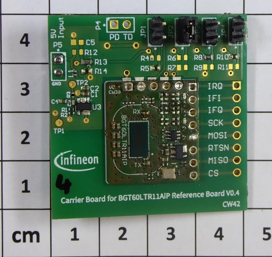
Click to zoom
Application Details
- Equipment Class
- DXX - Part 15 Low Power Communication Device Transmitter
- Date of Grant
- Mar 22, 2023
- Application Purpose
- Original Equipment
- Date of Application
- Mar 22, 2023
- Equipment Note
- 60 GHz Short Range Radar Module
- Frequency Range
- 61100.00000000 - 61400.00000000
- Company
- Infineon Technologies AG
- Country
- Germany
Documents & Files
Document Text
Text extracted from the exhibit documents filed with the FCC. Open a document above to read the original.
Users Manual
Reference design 60 GHz radar module based on BGT60LTR11 User manual and integration instructions Introduction User manual REF BGT60LTR11AIP 6 0 G H z p u l s e d D o p p l e r S h o r t R a n g e R a d a r / F i e l d D i s t u r b i n g S e n s o r About this document Scope and purpose This document briefly describes the function, circuitry, and performance of the 60 GHz autonomous reference design radar. The reference design provides the supporting circuitry to the on-board BGT60LTR11AIP monolithic microwave integrated circuit (SiP) Infineon’s 60 GHz radar chipset with antenna-in-package (AIP). The board is fully functional in autonomous mode, for low cost and user-friendly applications. Reference design 60 GHz radar module based on BGT60LTR11 User manual and integration instructions Introduction 1 Introduction The BGT60LTR11AIP SiP is a fully integrated microwave motion sensor including Antenna in Package (AIP), built-in motion and direction of motion detectors. The module „REF BGT60LTR11AIP” contains a NON RF section on FR4 carrier PCB and a RF section built by the mmW RF system in Package (SiP), where the BGT60LTR11 System on Chip (SoC) is extended by the package with mmW TX and RX antenna. The RF section, based on the mmW “Short Range Radar” (SRR) SoC, called in FCC area often “Field disturbing sensor” (FDS). This SoC includes the entire mmW RF section with VCO, mixer, PA, freq control, the state machine for sequence control, crystal oscillator (w.o. crystal resonator) and the baseband signal processing... The SoC is extended by the mmW TX and RX antenna on the top side of the package to become a full System in Package (SiP) solution. In the non RF, section there are only some assisting components e.g. for clock generation (crystal resonator), LDO section, level shifter, hard coded QS pins to operate the autonomous working mode and Vcc filter elements. The module is working without any external software. This small-sized radar solution is a compelling, smart and cost-effective replacement for conventional passive infrared (PIR) sensors in low-power or battery-powered applications. The SiP is designed to operate as a Doppler motion sensor in the 60 GHz ISM-band. In order to save power, the Doppler radar is highly duty cycled (pulsed). RF on time can be restricted to e.g. 1%. On this reference design, the SiP is working in autonomous mode, which can be selected via the QS1 pin. QS1 pin termination is fixed to act in the autonomous mode with internal signal processing to avoid the need of an external microcontroller. Beside QS1, the SiP has three additional input pins (QS2-4) to control signal processing parameter (to tailor the performance to the application) in autonomous mode and to adjust the RF frequency inside the 61.0 - 61.5 band. These pins are used for configuration of the SiP as explained below. In autonomous mode, the detection threshold (or sensitivity) is set via QS2 pin and has 15 different levels to select the targeted detection range from 0.5 m up to about 7 m for a typical human target Radar Cross-Section (RCS). The hold time is also configurable in 15 levels via QS3 pin, which allows detection status holding up to 30 minutes. The device operating frequency can be configured via QS4 pin and has 4 different possible frequencies between 61.1 and 61.4 GHz for BGT60LTR11AIP SiP. In this mode, the integrated detectors deliver digital output signals. One is indicating motion and the other one is indicating the direction of motion (approaching or departing) of a target. Reference design 60 GHz radar module based on BGT60LTR11 User manual and integration instructions Key features 2 Key features The BGT60LTR11AIP autonomous reference design is optimized for fast prototyping designs and system integrations, as well as initial product feature evaluations. In addition, the sensor can be integrated into systems like laptops, tablets, TVs, speakers etc. to ‘wake’ them up based on detected motion (or direction of motion), put them to sleep or auto-lock the system when no motion is detected for a defined amount of time. Radar sensors offer the possibility to hide them inside the end product since they operate through non-metallic materials. Therefore, it enables a seamless integration of technology in our daily live. Some key features of the BGT60LTR11AIP autonomous reference board are as follows: • Form factor of 20 mm x 18 mm for the BGT60LTR11AIP autonomous reference design • Features an AIP SiP of small size (6.7 mm x 3.3 mm x 0.56 mm), thereby eliminating antenna design complexity at the user end • Detects motion and direction of movement (approaching or departing) for a human target • Works standalone (autonomous mode) • Quartz oscillator built on chip, only external quartz resonator required on the module. LDO on module (Vcc = VIN = 3V3) • Configurable settings like operation mode, detector threshold, hold time, operating frequency via QS pins 2.1 Detection principle In this autonomous mode operation, the SiP uses only internal detectors for motion (TD = Target Detect) and direction of motion (PD Phase Detect) indication. TD and PD output ports are available via castellation at the PCB edge. Furthermore the status of these pins are reported via LEDs. 2.2 Battery-powered operation The Ref BGT60LTR11AIP autonomous reference board can operate independently with a battery that supplies to the VIN, and to the GND pin of the castellated holes or via other 2.7...4V power supply. The Ref BGT60LTR11AIP module can be soldered on a carrier board with Vcc preprocessing for more input voltage flexibility and to get a input voltage of e.g. 3V3 V for the module itself. 2.3 Board layout and detection settings The sensor configuration parameters are set via QS pins and external resistors. The BGT60LTR11AIP SiP has four quad-state inputs QS1-4. The default settings of these QS pins of the BGT60LTR11AIP autonoumous reference design are shown in figure 1, 2 and table 1, 2, 3. 2.4 Starting up the…
Text truncated - open the document above for the full version.
Attestation Statements
Date: February 2, 2023 The models with the FCC IC/ IC No. mentioned above are considered to meet this criteria since the module size is 20 mm x 18 mm and 4 pt font is the largest that can be used for module labelling which requires magnification for clear viewing. The FCC ID (per KDB 784748) and the IC No and the HVIN (with ISED's permission) will be displayed in the user manual . The FCC ID will also be placed on the device packaging or on a removable label attached to the device. FCC Justification Statement about Antenna Gain Information This device complies with the FCC limits for fundamental and spurious emissions solely by radiated measurements as documented in the test report. Therefore, neither antenna manufacturers data sheets, antenna reference design specification nor Antenna Under Test (AUT) reports as required for the FCC certification under CFR 47 Part 15.
Attestation Statements
CSA Group - External PHOENIX TESTLAB GmbH Date: March 27, 2023 Product Certification Department Koenigswinkel 10 32825 Blomberg Germany Attestation Certification designating a U.S. Agent for Service of Process Section 2.911(d)(7) (KDB 986446 D01 Covered Equipment) Infineon Technologies AG as required by section 2.911(d)(7), designate below contact located in the United States for purposes of acting as the applicant’s agent for service of process. The applicant also acceptance to maintain an agent for no less than one year after the grantee has terminated all marketing and importation or the conclusion of any Commission-related proceeding involving the equipment. Type of Equipment subject to FCC Certification: FCC ID: 2AYSQ60LTR11A1 Date of Application with TCB: January 24, 2023 Sincerely yours, Applicant/Grantee US Agent FCC FRN: 0033439175 Infineon Technologies AG Infineon Technologies Americas Corp. Alexander Glas Jagjit Singh Bal Lead Principal Senior Principal [email protected] [email protected] 95035 Milpitas CA North McCarthy Blvd 640
Attestation Statements
CSA Group - External PHOENIX TESTLAB GmbH Date: March 27, 2023 Product Certification Department Koenigswinkel 10 32825 Blomberg Germany Attestation Certification designating a U.S. Agent for Service of Process Section 2.911(d)(7) (KDB 986446 D01 Covered Equipment) Infineon Technologies AG as required by section 2.911(d)(7), designate below contact located in the United States for purposes of acting as the applicant’s agent for service of process. The applicant also acceptance to maintain an agent for no less than one year after the grantee has terminated all marketing and importation or the conclusion of any Commission-related proceeding involving the equipment. Type of Equipment subject to FCC Certification: FCC ID: 2AYSQ60LTR11A1 Date of Application with TCB: January 24, 2023 Sincerely yours, Applicant/Grantee US Agent FCC FRN: 0033439175 Infineon Technologies AG Infineon Technologies Americas Corp. Alexander Glas Jagjit Singh Bal Lead Principal Senior Principal [email protected] [email protected] 95035 Milpitas CA North McCarthy Blvd 640
Cover Letter(s)
nfi CSA lnternal | 3rd Party Request for Confidentialitv Date: December 13,2022 Subject: Confiäentiality Request for FCC ID: 2AYSQ60LTRI lAl and lC:28678-60LTR1 lAl Pursuant to FCC 47 CRF 0.457(d) and 0.459 and IC RSP-100, Section l2.4,the applicant requests that a parl of the subject FCC application be held confidential. Type of Confidentiality Requested Exhibit I Short Term fl Short Term ! Short Term ! Short Term ! Short Term I Short term I Short term I Short term n Short Term [l Permanent ! Permanent*l I Permanent I Permanent I Permanent I Permanent I Permanent*3 Block Diagrams External Photos Internal Photos Operation Description/Theory of Operation Parts List & Placement/BoM Tune-Up Procedure Schematics Test Setup Photos User's Manual Infineon Technologies AG has spent substantial effort in developing this product and it is one of the first of its kind in industry. Having the subject infomation easily available to "competition" would negate the advantage they have achieved by developing this product. Not protecting the details of the design will result in financial hardship. Permanent Confi dentiality: The applicant requests the exhibits listed above as permanently confidential be permanently withheld from public review due to materials that contain trade secrets and proprietary information not customarily released to the public. Short-Term Confi dentiality : The applicant requests the exhibits selected above as shoft term confidential be withheld from public view for a period of _(specifu number of days not to exceed I S0f_ days from the date of the Grant of Equipment Authorization and prior to marketing. This is to avoid premature release of sensitive information prior to marketing or release of the product to the public. Applicant is also aware that they are responsible to notify Phoenix Testlab GmbH in the event information regarding the product or the product is made available to the public. Phoenix Testlab GmbH will then release the documents listed above for public disclosure pursuant to FCC Public Notice DA 04-1705. NOTE for Industry Canada Applications: IC currently only distinguishes Permanent Confidentiality exhibits as shown above. Short Term confidentiality is not considered applicable to IC applications. Sincerely, By: { #u*,A, /. e"i "( (Sign n. ' ,, Alexander Glas / Lead Principal f/ /t, t lisc ( - The asterisked items (*) require futher information to be provided to ACB before permanent confidentiality will be extended to these exhibits. Please refer to FCC KDB 726920 and the specific Document link for D01 found at: https:/iapps.fcc.gov/oetcf/kdb/forms/FTSSearchResultPage.cfm?switch:P&id:41 73 I and review section II, 3) regarding specific information that must accompany these requests. - Please refer to http://acbceft.com/documents/misc-docs/Memo-Short-Term-Vs-Standard-Confidentiality.pdf for complete details. - Must be signed by applicant contact given for applicant on the FCC site, or by the authorized agent if an appropriate authorized agent letter has been provided. Letters should be placed on appropriate letterhead.
Cover Letter(s)
070920-02b CSA Internal | 3rd Party Request for Modular/Limited Modular Approval Date: February 2, 2023 Subject: Manufacturer’s Declaration for ☒ - Modular Approval ☐ - Split Modular Approval ☐ - Limited Modular Approval ☐ - Limited Split Modular Approval Request for: 2AYSQ60LTR11A1 8 Basic Requirements – FCC Part 15.212(a)(1) For Items Marked “NO(*)”, the Limited Module Description Must be Filled Out on the Following Pages Modular Approval Requirement Requirement Met 1. The modular transmitter must have its own RF shielding. This is intended to ensure that the module does not have to rely upon the shielding provided by the device into which it is installed in order for all modular transmitter emissions to comply with FCC limits. It is also intended to prevent coupling between the RF circuitry of the module and any wires or circuits in the device into which the module is installed. Such coupling may result in non-compliant operation. The physical crystal and tuning capacitors may be located external to the shielded radio elements. 15.212(a)(1)(i) ☒ - YES ☐ - NO(*) Details: The module contains a NON RF section on FR4 carrier PCB and a RF section built by the mmW RF system in Package (SiP), where the BGT60LTR11 Systen on Chip (SoC) is extended by the package with mmW TX and RX antenna In the NON RF section there are only assisting components e.g. for clock generation (crystal resonator), LDO section, Vcc filter elements and hard coded ports to select the autonomous working mode without external software. The RF section, based on the mmW “Field distribution sensor” (FDS) System in Package (SiP) BGT60LTR11AIP with TX and RX antenna in package. The naming Short Range Radar is common as well. This RF radar chip includes the state machine for process control, the entire TX and RX mmW section with on chip antennas, crystal oscillator (w.o.crystal resonator) and the baseband signal processing. A complete metal shielding of the RF SoP section and the entire radar module is not possible at any time, because the mmW antenna radiation (of the antennas on chip topside) would be blocked. The mmW Si chip is working in a shielded area. Description: Between the entire active area (the silicon die) and the on chip antenna for TX and RX, a ground plane for shielding is placed. Blow this shield GND, the Si mmW chip is located. Furthermore the mentioned shield GND is connected with vertical package through vias to the GND plane on the FR4 PCB. Both shield GND planes (the above the Si mmW Chip and the below one) are combined together via vertical package through vias and GND solderballs. These measures generates a 3D Faraday cage with the active RF silicon in the center. The radiation of the on chip antennas keeps unaffected. We referre strongly to the drawing in filed document “Autonomous BGT60LTR11AIP_Principle_Block diagram.docx” 2. The modular transmitter must have buffered modulation/data inputs (if such inputs are provided) to ensure that the module will comply with FCC requirements under conditions of excessive data rates or over-modulation. 15.212(a)(1)(ii) ☒ - YES ☐ - NO(*) ☒ - YES ☐ - NO(*) Details: The module does not have modulation input. ................................................................................................................................... 3. The modular transmitter must have its own power supply regulation on the module. This is intended to ensure that the module will comply with FCC requirements regardless of the design of the power supplying circuitry in the device into which the module is installed. 15.212(a)(1)(iii) Details: The module contains its own power supply regulation. LDO is on the module board. LDO marked in Schematic> 4. The modular transmitter must comply with the antenna and transmission system requirements of §§ 15.203, 15.204(b), 15.204(c), 15.212(a), and 2.929(b). The antenna must either be permanently attached or employ a ‘‘unique’’ antenna coupler (at all connections between the module and the antenna, including the cable). The ‘‘professional installation’’ provision of § 15.203 is not applicable to modules but can apply to limited modular approvals under paragraph 15.212(b). 15.212(a)(1)(iv) ☒ - YES ☐ - NO(*) Details: On chip antennas are used. NO other antenna can be connected to the chip. 070920-02b CSA Internal | 3rd Party 5. The modular transmitter must be tested in a stand-alone configuration, i.e., the module must not be inside another device during testing. This is intended to demonstrate that the module is capable of complying with Part 15 emission limits regardless of the device into which it is eventually installed. Unless the transmitter module will be battery powered, it must comply with the AC line conducted requirements found in Section 15.207. AC or DC power lines and data input/output lines connected to the module must not contain ferrites, unless they will be marketed with the module (see Section 15.27(a)). The length of these lines shall be length typical of actual use or, if that length is unknown, at least 10 centimeters to insure that there is no coupling between the case of the module and supporting equipment. Any accessories, peripherals, or support equipment connected to the module during testing shall be unmodified or commercially available (see Section 15.31(i)). 15.212(a)(1)(v) ☒ - YES ☐ - NO(*) Details: The module was tested stand-alone as shown in test setup photographs filed with this application> Modular Approval Requirement Requirement Met 6. The modular transmitter must be labeled with its own FCC ID number, or use an electron display (see KDB Publication 784748). If using a permanently affixed label with its own FCC ID number, if the FCC ID is not visible when the module is installed inside another device, then the outside of the device into which the module is installed must also display a label referring to the enclosed module. This exterior label can use wording such as the following: “Contains Transmitter Mo…
Text truncated - open the document above for the full version.
External Photos
The test report merely corresponds to the test sample. It is not permitted to copy extracts of these test results without the written permissi on of the test laboratory . CSA Group Bayern GmbH File No. 80103696-01 to 80103696-02, page 1 of 6 Ohmstrasse 1-4 94342 STRASSKIRCHEN GERMANY Tel.: +49(0)9424-94810 Fax: +49(0)9424-9481440 Rev. No. 5.0, 2020-02-11 CSA Confidential Attachment A Type / Model Name : REF BGT60LTR11AIP Product Description : 60 GHz short range radar module HVIN: Ref BGT60LTR11AIP_1 Applicant : Infineon Technologies AG Address : Am Campeon 1-15 85579 NEUBIBERG, GERMANY Manufacturer : Infineon Technologies AG Address : Am Campeon 1-15 85579 NEUBIBERG, GERMANY according to Test Report No. : 80103696-01 to 80103696-02 20. December 2022 ______________________________________________________________________________________________ Date of issue The test report merely corresponds to the test sample. It is not permitted to copy extracts of these test results without the written permissi on of the test laboratory . CSA Group Bayern GmbH File No. 80103696-01 to 80103696-02, page 2 of 6 Ohmstrasse 1-4 94342 STRASSKIRCHEN GERMANY Tel.: +49(0)9424-94810 Fax: +49(0)9424-9481440 Rev. No. 5.0, 2020-02-11 CSA Confidential Contents 1 P h o t o d o c u m e n t a t i o n o f t h e E U T 3 1.1 Overview 3 1.2 EUT #1 4 1.3 EUT #4 5 1.4 Ancilliary equipment 6 The test report merely corresponds to the test sample. It is not permitted to copy extracts of these test results without the written permissi on of the test laboratory . CSA Group Bayern GmbH File No. 80103696-01 to 80103696-02, page 3 of 6 Ohmstrasse 1-4 94342 STRASSKIRCHEN GERMANY Tel.: +49(0)9424-94810 Fax: +49(0)9424-9481440 Rev. No. 5.0, 2020-02-11 CSA Confidential 1 P h o t o d o c u m e n t a t i o n o f t h e E U T 1.1 Overview Back view of SRR module (EUT): Test jig SRR module (EUT) SRR RF chip w. antenna The test report merely corresponds to the test sample. It is not permitted to copy extracts of these test results without the written permissi on of the test laboratory . CSA Group Bayern GmbH File No. 80103696-01 to 80103696-02, page 4 of 6 Ohmstrasse 1-4 94342 STRASSKIRCHEN GERMANY Tel.: +49(0)9424-94810 Fax: +49(0)9424-9481440 Rev. No. 5.0, 2020-02-11 CSA Confidential 1.2 EUT #1 EUT #1 (CW) with test jig: The test report merely corresponds to the test sample. It is not permitted to copy extracts of these test results without the written permissi on of the test laboratory . CSA Group Bayern GmbH File No. 80103696-01 to 80103696-02, page 5 of 6 Ohmstrasse 1-4 94342 STRASSKIRCHEN GERMANY Tel.: +49(0)9424-94810 Fax: +49(0)9424-9481440 Rev. No. 5.0, 2020-02-11 CSA Confidential 1.3 EUT #4 EUT #4 (pulsed) with test jig: The test report merely corresponds to the test sample. It is not permitted to copy extracts of these test results without the written permissi on of the test laboratory . CSA Group Bayern GmbH File No. 80103696-01 to 80103696-02, page 6 of 6 Ohmstrasse 1-4 94342 STRASSKIRCHEN GERMANY Tel.: +49(0)9424-94810 Fax: +49(0)9424-9481440 Rev. No. 5.0, 2020-02-11 CSA Confidential 1.4 Ancilliary equipment AC/DC Adapter: - End of Attachment_A -
ID Label/Location Info
Date: February 2, 2023 The models with the FCC IC/ IC No. mentioned above are considered to meet this criteria since the module size is 20 mm x 18 mm and 4 pt font is the largest that can be used for module labelling which requires magnification for clear viewing. The FCC ID (per KDB 784748) and the IC No and the HVIN (with ISED's permission) will be displayed in the user manual . The FCC ID will also be placed on the device packaging or on a removable label attached to the device.
Internal Photos
The test report merely corresponds to the test sample. It is not permitted to copy extracts of these test results without the written permissi on of the test laboratory . CSA Group Bayern GmbH File No. 80103696-01 to 80103696-02, page 1 of 6 Ohmstrasse 1-4 94342 STRASSKIRCHEN GERMANY Tel.: +49(0)9424-94810 Fax: +49(0)9424-9481440 Rev. No. 5.0, 2020-02-11 CSA Confidential Attachment A Type / Model Name : REF BGT60LTR11AIP Product Description : 60 GHz short range radar module HVIN: Ref BGT60LTR11AIP_1 Applicant : Infineon Technologies AG Address : Am Campeon 1-15 85579 NEUBIBERG, GERMANY Manufacturer : Infineon Technologies AG Address : Am Campeon 1-15 85579 NEUBIBERG, GERMANY according to Test Report No. : 80103696-01 to 80103696-02 20. December 2022 ______________________________________________________________________________________________ Date of issue The test report merely corresponds to the test sample. It is not permitted to copy extracts of these test results without the written permissi on of the test laboratory . CSA Group Bayern GmbH File No. 80103696-01 to 80103696-02, page 2 of 6 Ohmstrasse 1-4 94342 STRASSKIRCHEN GERMANY Tel.: +49(0)9424-94810 Fax: +49(0)9424-9481440 Rev. No. 5.0, 2020-02-11 CSA Confidential Contents 1 P h o t o d o c u m e n t a t i o n o f t h e E U T 3 1.1 Overview 3 1.2 EUT #1 4 1.3 EUT #4 5 1.4 Ancilliary equipment 6 The test report merely corresponds to the test sample. It is not permitted to copy extracts of these test results without the written permissi on of the test laboratory . CSA Group Bayern GmbH File No. 80103696-01 to 80103696-02, page 3 of 6 Ohmstrasse 1-4 94342 STRASSKIRCHEN GERMANY Tel.: +49(0)9424-94810 Fax: +49(0)9424-9481440 Rev. No. 5.0, 2020-02-11 CSA Confidential 1 P h o t o d o c u m e n t a t i o n o f t h e E U T 1.1 Overview Back view of SRR module (EUT): Test jig SRR module (EUT) SRR RF chip w. antenna The test report merely corresponds to the test sample. It is not permitted to copy extracts of these test results without the written permissi on of the test laboratory . CSA Group Bayern GmbH File No. 80103696-01 to 80103696-02, page 4 of 6 Ohmstrasse 1-4 94342 STRASSKIRCHEN GERMANY Tel.: +49(0)9424-94810 Fax: +49(0)9424-9481440 Rev. No. 5.0, 2020-02-11 CSA Confidential 1.2 EUT #1 EUT #1 (CW) with test jig: The test report merely corresponds to the test sample. It is not permitted to copy extracts of these test results without the written permissi on of the test laboratory . CSA Group Bayern GmbH File No. 80103696-01 to 80103696-02, page 5 of 6 Ohmstrasse 1-4 94342 STRASSKIRCHEN GERMANY Tel.: +49(0)9424-94810 Fax: +49(0)9424-9481440 Rev. No. 5.0, 2020-02-11 CSA Confidential 1.3 EUT #4 EUT #4 (pulsed) with test jig: The test report merely corresponds to the test sample. It is not permitted to copy extracts of these test results without the written permissi on of the test laboratory . CSA Group Bayern GmbH File No. 80103696-01 to 80103696-02, page 6 of 6 Ohmstrasse 1-4 94342 STRASSKIRCHEN GERMANY Tel.: +49(0)9424-94810 Fax: +49(0)9424-9481440 Rev. No. 5.0, 2020-02-11 CSA Confidential 1.4 Ancilliary equipment AC/DC Adapter: - End of Attachment_A -
RF Exposure Info
The test report merely corresponds to the test sample. It is not permitted to copy extracts of these test results without the written permissi on of the test laboratory . CSA Group Bayern GmbH File No. 80103696-02 Rev_1, page 1 of 12 Ohmstrasse 1-4 94342 STRASSKIRCHEN GERMANY Tel.: +49(0)9424-94810 Fax: +49(0)9424-9481440 Rev. No. 6.3, 2021-11-03 CSA Group Confidential - Internal R F − T E S T R E P O R T - Human Exposure - Type / Model Name : REF BGT60LTR11AIP Product Description : 60 GHz short range radar module HVIN: Ref BGT60LTR11AIP_1 Applicant : Infineon Technologies AG Address : Am Campeon 1-15 85579 NEUBIBERG, GERMANY Manufacturer : Infineon Technologies AG Address : Am Campeon 1-15 85579 NEUBIBERG, GERMANY Test Result according to the standards listed in clause 1 test standards: POSITIVE Test Report No. : 80103696-02 Rev_1 03. February 2023 ______________________________________________________________________________________________ Date of issue The test report merely corresponds to the test sample. It is not permitted to copy extracts of these test results without the written permissi on of the test laboratory . FCC ID: 2AYSQ60LTR11A1 IC: 28678-60LTR11A1 CSA Group Bayern GmbH File No. 80103696-02 Rev_1, page 2 of 12 Ohmstrasse 1-4 94342 STRASSKIRCHEN GERMANY Tel.: +49(0)9424-94810 Fax: +49(0)9424-9481440 Rev. No. 6.3, 2021-11-03 CSA Group Confidential - Internal Contents 1 T E S T S T A N D A R D S 3 2 E Q U I P M E N T U N D E R T E S T 4 2.1 Information provided by the Client 4 2.2 Sampling 4 2.3 Photo documentation of the EUT – see Attachment A 4 2.4 Equipment type, category 4 2.5 Short description of the equipment under test (EUT) 4 2.6 Variants of the EUT 4 2.7 Operation frequency and channel plan 4 2.8 Transmit operating modes 5 2.9 Antennas 5 2.10 Power supply system utilised 5 3 T E S T R E S U L T S U M M A R Y 6 3.1 Revision history of test report 6 3.2 Final assessment 6 4 T E S T E N V I R O N M E N T 7 4.1 Address of the test laboratory 7 4.2 Environmental conditions 7 4.3 Statement of the measurement uncertainty 7 5 H U M A N E X P O S U R E 8 5.1 RF output power 8 5.2 Maximum permissible exposure (MPE) 9 5.3 Co-location and Co-transmission 11 5.4 SAR test exclusion considerations 11 5.5 Exemption limits for routine evaluation - SAR evaluation 11 6 U S E D T E S T E Q U I P M E N T A N D A C C E S S OR I E S 12 A T T A C H M E N T A A S S E P A R A T E S U P P L E M E N T The test report merely corresponds to the test sample. It is not permitted to copy extracts of these test results without the written permissi on of the test laboratory . FCC ID: 2AYSQ60LTR11A1 IC: 28678-60LTR11A1 CSA Group Bayern GmbH File No. 80103696-02 Rev_1, page 3 of 12 Ohmstrasse 1-4 94342 STRASSKIRCHEN GERMANY Tel.: +49(0)9424-94810 Fax: +49(0)9424-9481440 Rev. No. 6.3, 2021-11-03 CSA Group Confidential - Internal 1 T E S T S T A N D A R D S The tests were performed according to following standards: FCC Rules and Regulations Part 1, Subpart I - Procedures Implementing the National Environmental Policy Act of 1969 Part 1, Subpart I, Section 1.1310 Radiofrequency radiation exposure limits Part 1, Subpart 2, Section 2.1091 Radiofrequency radiation exposure evaluation: mobile devices. KDB 447498 D01 RF Exposure procedures and equipment authorisation policies for mobile and portable devices, April 20, 2021. ANSI C95.1: 2005 IEEE Standard for Safety Levels with respect to Human Exposure to Radio Frequency Electromagnetic Fields, 3 kHz to 300 GHz RSS-102, Issue 5, February 2, 2021 Radio Frequency (RF) Exposure Compliance of Radiocommunication Apparatus (All Frequency Bands) ANSI C95.1: 2005 IEEE Standard for Safety Levels with respect to Human Exposure to Radio Frequency Electromagnetic Fields, 3 kHz to 300 GHz The test report merely corresponds to the test sample. It is not permitted to copy extracts of these test results without the written permissi on of the test laboratory . FCC ID: 2AYSQ60LTR11A1 IC: 28678-60LTR11A1 CSA Group Bayern GmbH File No. 80103696-02 Rev_1, page 4 of 12 Ohmstrasse 1-4 94342 STRASSKIRCHEN GERMANY Tel.: +49(0)9424-94810 Fax: +49(0)9424-9481440 Rev. No. 6.3, 2021-11-03 CSA Group Confidential - Internal 2 E Q U I P M E N T U N D E R T E S T 2.1 Information provided by the Client Please note, we do not take any responsibility for information provided by the client or his representative which may have an influence on the validity of the test results. 2.2 Sampling The customer is responsible for the choice of sample. Sample configuration, start-up and operation is carried out by the customer or according his/her instructions. 2.3 Photo documentation of the EUT – see Attachment A 2.4 Equipment type, category The EUT qualifies under FCC 15.255, (c)(2), field disturbance sensor, fixed equipment 2.5 Short description of the equipment under test (EUT) The EUT is a field disturbance sensor in the operating band of 61.0 GHz to 61.5 GHz. Number of tested sa…
Text truncated - open the document above for the full version.
Contact Information
Applicant
Alexander Glas(Lead Principal)
Test Firm
CSA Group Bayern GmbHFrank Scharnowski
[email protected]+49 9931 9836 140
Technical Specifications
| # | Rule Parts | Frequency Range | Power Output |
|---|---|---|---|
| 1 | 15C | 61.10 GHz - 61.40 GHz | - |