2AYSQBGT60CUTR13-ARadar surface-mounted device (SMD) module
Infineon Technologies AG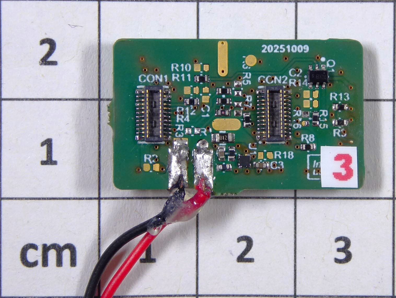
Click to zoom
Application Details
- Equipment Class
- FDS - Part 15 Field Disturbance Sensor
- Date of Grant
- Jul 20, 2026
- Application Purpose
- Original Equipment
- Equipment Note
- Radar surface-mounted device (SMD) module
- Frequency Range
- 59440.00000000 - 61560.00000000
- Company
- Infineon Technologies AG
- Country
- Germany
Documents & Files
Document Text
Text extracted from the exhibit documents filed with the FCC. Open a document above to read the original.
Users Manual
User guide Please read the Important Notice at the end of this document Revision 1.00 www.infineon.com 2026-02-27 UG105041 XENSIV™ BGT60CUTR13AIP CMOS radar SMD module 6 0 G H z F M C W s h o r t r a n g e r a d a r / f i e l d d i s t u r b i n g s e n s o r About this document Scope and purpose This document describes the function, circuitry, and performance of the full modular certified surface-mounted device (SMD) reference design for the XENSIV™ BGT60CUTR13AIP CMOS radar sensor. It also provides integration guidelines for host product manufacturers to integrate the radar module into their products, and documentation of the test modes used in the FCC and CE certification process. Intended audience The intended audience for this document are host product manufacturers who intend to integrate the Infineon XENSIV™ BGT60CUTR13AIP CMOS radar SMD module into their design. About this product group Target applications HVAC, smart home and building, smart TV, smart displays, security cameras, lighting, security devices, wearables, robotics, healthcare devices, etc. Product family XENSIV™ 60 GHz CMOS radar sensors for IoT Manufacturer Information: Infineon Technologies AG Am Campeon 1 - 15 85579 Neubiberg Germany FCC ID: 2AYSQBGT60CUTR13 - A User guide 2 Revision 1.00 2026-02-27 XENSIV™ BGT60CUTR13AIP CMOS radar SMD module 60 GHz FMCW short range radar/field disturbing sensor Safety precautions Safety precautions Note: Please note the following warnings regarding the hazards associated with development systems. Table 1 Safety precautions Caution: The evaluation or reference board contains parts and assemblies sensitive to electrostatic discharge (ESD). Electrostatic control precautions are required when installing, testing, servicing or repairing the assembly. Component damage may result if ESD control procedures are not followed. If you are not familiar with electrostatic control procedures, refer to the applicable ESD protection handbooks and guidelines. User guide 3 Revision 1.00 2026-02-27 XENSIV™ BGT60CUTR13AIP CMOS radar SMD module 60 GHz FMCW short range radar/field disturbing sensor Table of contents Table of contents About this document ....................................................................................................................... 1 About this product group ................................................................................................................. 1 Safety precautions .......................................................................................................................... 2 Table of contents ............................................................................................................................ 3 1 The board at a glance .............................................................................................................. 5 1.1 Main features ........................................................................................................................................... 5 2 System and functional description ........................................................................................... 8 2.1 Getting started......................................................................................................................................... 8 2.2 BGT60CUTR13AIP radar operation modes ............................................................................................. 9 2.2.1 On-chip autonomous mode: Radar SoC with HWA only (no MCU required).................................. 10 2.2.2 On-chip enhanced solution: Radar SoC with HWA (and limited code on MCU) ............................. 10 2.2.3 Premium turnkey solution: Radar SoC with MCU (SPI data forwarding to MCU, advanced processing on MCU) ......................................................................................................................... 11 2.3 Module interface and carrier board recommendations ...................................................................... 11 3 System performance ............................................................................................................. 14 3.1 Test modes ............................................................................................................................................ 15 3.2 Test hardware ........................................................................................................................................ 16 3.3 Test results ............................................................................................................................................ 17 4 System design ...................................................................................................................... 22 4.1 Schematics ............................................................................................................................................ 22 4.2 Layout .................................................................................................................................................... 25 4.3 Bill of materials ...................................................................................................................................... 26 5 Integration instructions ......................................................................................................... 27 5.1 Integration of radar module into the host product to avoid interference .......................................... 27 5.2 Radome design and integration guide ................................................................................................. 27 5.2.1 Material considerations ................................................................................................................... 27 5.2.2 Mechanical considerations .............................................................................................................. 28 5.2.3 Summary ........................…
Text truncated - open the document above for the full version.
ID Label/Location Info
CSA Internal | 3rd Party Dat. 06.3.26 FCC ID: 2AYSQBGT60CUTR13-A FCC Label & Location • FCC: Per KDB 784748 the marking may be placed in the user manual and packaging if the device is unquestionably too small to be readable (smaller than 4 pt font). • The models with the FCC ID No. mentioned above are considered to meet this criteria since the module size is 17.7 mm x 12 mm and 4 pt font is the largest that can be used for module labelling which requires magnification for clear viewing. The certification numbers FCC (per KDB 784748) will be displayed in the user manual and packaging. Patrick Schuster (Signature1) Title:Staff Engineer On behalf of: Infineon Technologies AG Telephone: +49 89 234 35319 Email:[email protected] 1 - Must be signed by applicant contact given for applicant on the FCC site, or by the authorized agent if an appropriate authorized agent letter has been provided. Letters should be placed on appropriate letterhead.
Test Setup Photos
The test report merely corresponds to the test sample. It is not permitted to copy extracts of these test results without the written permissi on of the test laboratory . CSA Group Bayern GmbH File No. 80260692-00, page 1 of 8 Straubinger Strasse 100 94447 PLATTLING GERMANY Tel.: +49(0)9931-98360 Rev. No. 5.0, 2020-02-11 Attachment B Type / Model Name : BGT60CUTR13AIP Product Description : 60 GHz short range radar module HVIN: BGT60CUTR13AIP-SMD Applicant : Infineon Technologies AG Address : Am Campeon 1-15 85579 NEUBIBERG, GERMANY Manufacturer : Infineon Technologies AG Address : Am Campeon 1-15 85579 NEUBIBERG, GERMANY according to Test Report No. : 80260692-00 27. May 2026 ______________________________________________________________________________________________ Date of issue The test report merely corresponds to the test sample. It is not permitted to copy extracts of these test results without the written permissi on of the test laboratory . CSA Group Bayern GmbH File No. 80260692-00, page 2 of 8 Straubinger Strasse 100 94447 PLATTLING GERMANY Tel.: +49(0)9931-98360 Rev. No. 5.0, 2020-02-11 Contents 1 T e s t s e t u p P h o t o s 3 1.1 A4 3 1.2 CPR3, DC, MB 4 1.3 SER1, SER2, SER3 5 1.4 FE 8 The test report merely corresponds to the test sample. It is not permitted to copy extracts of these test results without the written permissi on of the test laboratory . CSA Group Bayern GmbH File No. 80260692-00, page 3 of 8 Straubinger Strasse 100 94447 PLATTLING GERMANY Tel.: +49(0)9931-98360 Rev. No. 5.0, 2020-02-11 1 T e s t s e t u p P h o t os 1.1 A4 Shielded Room SR2: The test report merely corresponds to the test sample. It is not permitted to copy extracts of these test results without the written permissi on of the test laboratory . CSA Group Bayern GmbH File No. 80260692-00, page 4 of 8 Straubinger Strasse 100 94447 PLATTLING GERMANY Tel.: +49(0)9931-98360 Rev. No. 5.0, 2020-02-11 1.2 CPR3, DC, MB Fully Anechoic Room FAR1 EUT orientation: X V H The test report merely corresponds to the test sample. It is not permitted to copy extracts of these test results without the written permissi on of the test laboratory . CSA Group Bayern GmbH File No. 80260692-00, page 5 of 8 Straubinger Strasse 100 94447 PLATTLING GERMANY Tel.: +49(0)9931-98360 Rev. No. 5.0, 2020-02-11 1.3 SER1, SER2, SER3 Semi Anechoic Chamber SAC2: 9 kHz – 30 MHz: 30 MHz – 1 GHz: The test report merely corresponds to the test sample. It is not permitted to copy extracts of these test results without the written permissi on of the test laboratory . CSA Group Bayern GmbH File No. 80260692-00, page 6 of 8 Straubinger Strasse 100 94447 PLATTLING GERMANY Tel.: +49(0)9931-98360 Rev. No. 5.0, 2020-02-11 Fully Anechoic Room FAR1: 1 GHz – 18 GHz: 18 GHz – 40 GHz: The test report merely corresponds to the test sample. It is not permitted to copy extracts of these test results without the written permissi on of the test laboratory . CSA Group Bayern GmbH File No. 80260692-00, page 7 of 8 Straubinger Strasse 100 94447 PLATTLING GERMANY Tel.: +49(0)9931-98360 Rev. No. 5.0, 2020-02-11 40 GHz – 200 GHz: EUT orientation: X V H The test report merely corresponds to the test sample. It is not permitted to copy extracts of these test results without the written permissi on of the test laboratory . CSA Group Bayern GmbH File No. 80260692-00, page 8 of 8 Straubinger Strasse 100 94447 PLATTLING GERMANY Tel.: +49(0)9931-98360 Rev. No. 5.0, 2020-02-11 1.4 FE Climatic Chamber AREA 4: - End of Attachment B -
Test Report
The test report merely corresponds to the test sample. It is not permitted to copy extracts of these test results without the written permissi on of the test laboratory . CSA Group Bayern GmbH File No. 80260692-00 Rev_1, page 1 of 52 Straubinger Strasse 100 94447 PLATTLING GERMANY Tel.: +49(0)9931-98360 Rev. No. 7.0, 2025-01-24 R F − T E S T R E P O R T - FCC Part 15.255 / RSS-210 - Type / Model Name : BGT60CUTR13AIP Product Description : 60 GHz short range radar module HVIN: BGT60CUTR13AIP-SMD Applicant : Infineon Technologies AG Address : Am Campeon 1-15 85579 NEUBIBERG, GERMANY Manufacturer : Infineon Technologies AG Address : Am Campeon 1-15 85579 NEUBIBERG, GERMANY Test Result according to the standards listed in clause 1 test standards: POSITIVE Test Report No. : 80260692-00 Rev_1 27. May 2026 ______________________________________________________________________________________________ Date of issue The test report merely corresponds to the test sample. It is not permitted to copy extracts of these test results without the written permissi on of the test laboratory . CSA Group Bayern GmbH File No. 80260692-00 Rev_1, page 2 of 52 Straubinger Strasse 100 94447 PLATTLING GERMANY Tel.: +49(0)9931-98360 Rev. No. 7.0, 2025-01-24 Contents 1 T E S T S T A N D A R D S 3 2 E Q U I P M E N T U N D E R T E S T 4 2.1 Information provided by the Client 4 2.2 Sampling 4 2.3 Photo documentation of the EUT – Detailed photos see ATTACHMENT A 4 2.4 Equipment type 4 2.5 Short description of the equipment under test (EUT) 4 2.6 Variants of the EUT 4 2.7 Operation frequency 4 2.8 Transmit operating modes 4 2.9 Antenna 4 2.10 Power supply system utilised 5 2.11 Peripheral devices and interface cables 5 2.12 Determination of worst-case conditions for final measurement 5 3 T E S T R E S U L T S U M M A R Y 6 3.1 Revision history of test report 6 3.2 Final assessment 7 4 T E S T E N V I R O N M E N T 8 4.1 Address of the test laboratory 8 4.2 Environmental conditions 8 4.3 Statement of the measurement uncertainty 8 4.4 Conformity Decision Rule 8 4.5 Measurement protocol for FCC and ISED 9 5 T E S T C O N D I T I O N S A N D R E S U L T S 13 5.1 AC power line conducted emissions 13 5.2 OBW 19 5.3 EIRP and transmitter off-times 22 5.4 Spurious emissions 27 5.5 Frequency stability 45 5.6 Antenna requirement 48 6 U S E D T E S T E Q U I P M E N T A N D A C C E S S O R I E S 49 7 D E T A I L E D M E A S U R E M E N T U N C E R T A I N T Y 52 ATTACHMENTs A, B as separate supplements The test report merely corresponds to the test sample. It is not permitted to copy extracts of these test results without the written permissi on of the test laboratory . CSA Group Bayern GmbH File No. 80260692-00 Rev_1, page 3 of 52 Straubinger Strasse 100 94447 PLATTLING GERMANY Tel.: +49(0)9931-98360 Rev. No. 7.0, 2025-01-24 1 T E S T S T A N D A R D S The tests were performed according to following standards: FCC Rules and Regulations (November 2025) Part 15, Subpart A General Part 15, Subpart C, Section 15.255 Operation within the band 57-71 GHz. ANSI C63.10-2020 + Cor. 1-2023 + Testing Unlicensed Wireless Devices C63.10a-2024 + Errata to C63.10a-2024 KDB 364244 D01 V01 Meas 15.255 Radars ISED Canada Rules and Regulations RSS-Gen, Issue 5 + Amendment 1 + 2 General Requirements for Compliance of Radio Apparatus RSS-210, Issue 11 Licence-Exempt Radio Apparatus: Category I Equipment ANSI C63.10-2020 + Cor. 1-2023 + Testing Unlicensed Wireless Devices C63.10a-2024 + Errata to C63.10a-2024 KDB 364244 D01 V01 Meas 15.255 Radars The test report merely corresponds to the test sample. It is not permitted to copy extracts of these test results without the written permissi on of the test laboratory . CSA Group Bayern GmbH File No. 80260692-00 Rev_1, page 4 of 52 Straubinger Strasse 100 94447 PLATTLING GERMANY Tel.: +49(0)9931-98360 Rev. No. 7.0, 2025-01-24 2 E Q U I P M E N T U N D E R T E S T 2.1 Information provided by the Client Please note, we do not take any responsibility for information provided by the client or his representative which may have an influence on the validity of the test results. 2.2 Sampling The customer is responsible for the choice of sample. Sample configuration, start-up and operation is carried out by the customer or according his/her instructions. 2.3 Photo documentation of the EUT – Detailed photos see ATTACHMENT A 2.4 Equipment type The EUT qualifies under FCC §15.255(c)(2)(v) and RSS-210 J.3.2.a as a field disturbance sensor, and under FCC §15.255(c)(2)(ii) and RSS-210 J.3.2.b.ii as a field disturbance sensor. 2.5 Short description of the equipment under test (EUT) The EUT is a field disturbance sensor. It has two operation modes, working in the frequency band of 61 GHz to 61.5 GHz (Mode 1) and in the frequency band of 57 GHz to 61.56 GHz (Mode 2 - used frequency range only 59.44 GHz to 61.56 GHz) using FMCW. Number of tested samples: 1 Serial number: RF sample #3 Firmware ID: Not applicable, EUT is not equipped with programmable device FCC ID: 2AYSQBGT60CUTR13-A IC ID: 28678-BGT60CUTR13 HVIN: BGT60CUTR13AIP-SMD 2.6 Variants of the EUT There are no variants. 2.7 Operation frequency Operating frequency range 1: 61 GHz to 61.5 GHz Operating frequency range 2: 59.44 GHz to 61.56 GHz 2.8 Transmit operating modes The EUT allows the user to select the following modes: - TX modulated 2.9 Antenna The following integrated antennas are used with the EUT: Number Characteristic Model number Plug Frequency range (GHz) Typ. gain (dBi) 1 linear On chip patch antenna for TX - 57 - 64 3 2 linear On chip patch antenna for RX - 57 - 64 3 3 linear On chip patch antenna for RX - 57 - 64 3 4 linear On chip patch antenna for RX - 57 - 64 3 The test report merely corresponds to the test sample. It is not permitted to copy extracts of these test results without the written permissi on of the test laboratory . CSA Group Bayern GmbH File No. 80260692-00 Rev_1, page 5 of 52 Straubinger Strasse 100 94447 PLATTL…
Text truncated - open the document above for the full version.
Schematics
1 Schematics Figure 1 Schematic overview of Xensiv TM BGT60CUTR13AIP SMD module Figure 2 Schematic of the Xensiv TM BGT60CUTR13AIP SMD module power supply circuitry Figure 3 Schematic of the Xensiv TM BGT60CUTR13AIP SMD module XTAL resonator circuitry Figure 4 Schematic of the Xensiv TM BGT60CUTR13AIP SMD module radar SoC circuitry Figure 5 Schematic of the Xensiv TM BGT60CUTR13AIP SMD module half stamp hole connectors
RF Exposure Info
The test report merely corresponds to the test sample. It is not permitted to copy extracts of these test results without the written permissi on of the test laboratory . CSA Group Bayern GmbH File No. 80260692-01 Rev_0, page 1 of 10 Straubinger Strasse 100 94447 PLATTLING GERMANY Tel.: +49(0)9931-98360 Rev. No. 6.4, 2024-07-04 R F − T E S T R E P O R T - Human Exposure - Type / Model Name : BGT60CUTR13AIP Product Description : 60 GHz short range radar module HVIN: BGT60CUTR13AIP-SMD Applicant : Infineon Technologies AG Address : Am Campeon 1-15 85579 NEUBIBERG, GERMANY Manufacturer : Infineon Technologies AG Address : Am Campeon 1-15 85579 NEUBIBERG, GERMANY Test Result according to the standards listed in clause 1 test standards: POSITIVE Test Report No. : 80260692-01 Rev_0 14. January 2026 ______________________________________________________________________________________________ Date of issue The test report merely corresponds to the test sample. It is not permitted to copy extracts of these test results without the written permissi on of the test laboratory . CSA Group Bayern GmbH File No. 80260692-01 Rev_0, page 2 of 10 Straubinger Strasse 100 94447 PLATTLING GERMANY Tel.: +49(0)9931-98360 Rev. No. 6.4, 2024-07-04 Contents 1 T E S T S T A N D A R D S 3 2 E Q U I P M E N T U N D E R T E S T 4 2.1 Information provided by the Client 4 2.2 Sampling 4 2.3 Photo documentation of the EUT – see Attachment A 4 2.4 Equipment type, category 4 2.5 Short description of the equipment under test (EUT) 4 2.6 Variants of the EUT 4 2.7 Operation frequency and channel plan 4 2.8 Transmit operating modes 4 2.9 Antennas 4 2.10 Power supply system utilised 5 2.11 Peripheral devices and interface cables 5 2.12 Determination of worst case conditions for final measurement 5 3 T E S T R E S U L T S U M M A R Y 6 3.1 Revision history of test report 6 3.2 Final assessment 6 4 T E S T E N V I R O N M E N T 7 4.1 Address of the test laboratory 7 4.2 Environmental conditions 7 4.3 Statement of the measurement uncertainty 7 4.4 Conformity Decision Rule 7 5 H U M A N E X P O S U R E 8 5.1 RF output power 8 5.1 Maximum permissible exposure (MPE) according to FCC 9 5.1 Maximum permissible exposure (MPE) according to ISED 10 ATTACHMENT A as separate supplement The test report merely corresponds to the test sample. It is not permitted to copy extracts of these test results without the written permissi on of the test laboratory . CSA Group Bayern GmbH File No. 80260692-01 Rev_0, page 3 of 10 Straubinger Strasse 100 94447 PLATTLING GERMANY Tel.: +49(0)9931-98360 Rev. No. 6.4, 2024-07-04 1 T E S T S T A N D A R D S The tests were performed according to following standards: FCC Rules and Regulations: Part 1, Subpart I, Section 1.1310 Radiofrequency radiation exposure limits Part 2, Subpart J, Section 2.1091 Radiofrequency radiation exposure evaluation: mobile devices. KDB 447498 D01 V06 General RF Exposure Guidance ISED Canada Rules and Regulations: RSS-102, Issue 6 Radio Frequency (RF) Exposure Compliance of Radiocommunication Apparatus (All Frequency Bands) The test report merely corresponds to the test sample. It is not permitted to copy extracts of these test results without the written permissi on of the test laboratory . CSA Group Bayern GmbH File No. 80260692-01 Rev_0, page 4 of 10 Straubinger Strasse 100 94447 PLATTLING GERMANY Tel.: +49(0)9931-98360 Rev. No. 6.4, 2024-07-04 2 E Q U I P M E N T U N D E R T E S T 2.1 Information provided by the Client Please note, we do not take any responsibility for information provided by the client or his representative which may have an influence on the validity of the test results. 2.2 Sampling The customer is responsible for the choice of sample. Sample configuration, start-up and operation is carried out by the customer or according his/her instructions. 2.3 Photo documentation of the EUT – see Attachment A 2.4 Equipment type, category The EUT qualifies under FCC §15.255(c)(2)(v) and RSS-210 J.3.2.a as a field disturbance sensor, and under FCC §15.255(c)(2)(ii) and RSS-210 J.3.2.b.ii as a field disturbance sensor. 2.5 Short description of the equipment under test (EUT) The EUT is a field disturbance sensor. It has two operation modes, working in the frequency band of 61 GHz to 61.5 GHz (Mode 1) and in the frequency band of 57 GHz to 61.56 GHz (Mode 2 - used frequency range only 59.44 GHz to 61.56 GHz) using FMCW. Number of tested samples: 1 Serial number: RF sample #3 Firmware ID: Not applicable, EUT is not equipped with programmable device FCC ID: 2AYSQBGT60CUTR13-A IC ID: 28678-BGT60CUTR13 HVIN: BGT60CUTR13AIP-SMD 2.6 Variants of the EUT There are no variants. 2.7 Operation frequency and channel plan Operating frequency range 1: 61 GHz to 61.5 GHz Operating frequency range 2: 59.44 GHz to 61.56 GHz 2.8 Transmit operating modes The EUT allows the user to select the following modes: - TX modulated 2.9 Antennas The following integrated antennas are used with the EUT: Number Characteristic Model number Plug Frequency range (GHz) Typ. gain (dBi) 1 linear On chip patch antenna for TX - 57 - 64 3 2 linear On chip patch antenna for RX - 57 - 64 3 3 linear On chip patch antenna for RX - 57 - 64 3 4 linear On chip patch antenna for RX - 57 - 64 3 The test report merely corresponds to the test sample. It is not permitted to copy extracts of these test results without the written permissi on of the test laboratory . CSA Group Bayern GmbH File No. 80260692-01 Rev_0, page 5 of 10 Straubinger Strasse 100 94447 PLATTLING GERMANY Tel.: +49(0)9931-98360 Rev. No. 6.4, 2024-07-04 The antennas cannot be unattached by the user. 2.10 Power supply system utilised Power supply voltage EUT : 2.6 – 4.7 V/DC (V nom = 3.3 V/DC) Power supply voltage, test jig : 4.5 V/DC (3x AAA battery) 2.11 Peripheral devices and interface cables The following peripheral devices and interface cables are connected during the measurements: - Battery pack with USB cable Model : custom-built by cus…
Text truncated - open the document above for the full version.
Internal Photos
Photo of the underside of the module:
ID Label/Location Info
FCC ID: 2AYSQBGT60CUTR13-AFCC ID: 2AYSQBGT60CUTR13-A
External Photos
Photo of the underside of the module:
Cover Letter(s)
Request for Confidentiality Date: 0.6.1026 Subject: Confidentiality Request for FCC ID: 2AYSQBGT60CUTR13-A Pursuant to FCC 47 CRF 0.457(d) and 0.459, the applicant requests that a part of the subject FCC application be held confidential. c Type of Confidentiality Requested Short Term X Permanent □ Short Term Short Term □ Permanent*1 □ Short Term Permanent Short Term□ Permanent □ Short TermPermanent Short TermzPermanent □ Short Term Short Term Q Permanent*3 Exhibit Block Diagrams External Photos Internal Photos Operation Description/Theory of Operation Parts List & Placement/BOM Tune-Up Procedure Schematics Test Setup Photos User’s Manual Infineon Technologies AG has spent substantial effort in developing this product and it is one of the first of its kind in industry. Having the subject information easily available to "competition" would negate the advantage they have achieved by developing this product. Not protecting the details of the design will result in financial hardship. Permanent Confidentiality: The applicant requests the exhibits listed above as permanently confidential be permanently withheld from public review due to materials that contain trade secrets and proprietary information not customarily released to the public. Short-Term Confidentiality: The applicant requests the exhibits selected above as short term confidential be withheld from public view for a period of 0 days from the date of the Grant of Equipment Authorization and prior to marketing. This is to avoid premature release of sensitive information prior to marketing or release of the product to the public. Applicant is also aware that they are responsible to notify Phoenix Testlab GmbH in the event information regarding the product or the product is made available to the public. Phoenix Testlab GmbH will then release the documents listed above for public disclosure pursuant to FCC Public Notice DA 04-1705. Sincerely, By:/Staff Engineer (Signature/Title2) Patrick Schuster (Print name) 1 - The asterisked items (*) require further information to be provided to the TCB before permanent confidentiality will be extended to these exhibits. Please refer to FCC KDB 726920 and the specific Document link for DOI found at: https://apps.fcc.gov/oetcf/kdb/forms/FTSSearchResultPage.cfm?switch=P&id=41731 and review section II, 3) regarding specific information that must accompany these requests. 2 - Must be signed by applicant contact given for applicant on the FCC site, or by the authorized agent if an appropriate authorized agent letter has been provided. Letters should be placed on appropriate letterhead.
Cover Letter(s)
CSA Internal | 3rd Party Request for Modular/Limited Modular Approval Date: Subject: Manufacturer’s Declaration for 13 - Modular Approval □ - Limited Modular Approval □ - Split Modular Approval □ - Limited Split Modular Approval Confidentiality Request for:2AYSQBGT60CUTR13-A 1. 8 Basic Requirements - FCC Part 15.212(a)(1) For Items Marked “NO(*)”, the Limited Module Description Must be Filled Out on the Following Pages __________________________Modular Approval Requirement_______________________________ The modular transmitter must have its own RF shielding. This is intended to ensure that the module does not have to rely upon the shielding provided by the device into which it is installed in order for all modular transmitter emissions to comply with FCC limits. It is also intended to prevent coupling between the RF circuitry of the module and any wires or circuits in the device into which the module is installed. Such coupling may result in non-compliant operation. The physical crystal and tuning capacitors may be located external to the shielded radio elements. 15.212(a)(l)(i) Requirement Met 13 - YES □ - NO(*) Details: The modular transmitter contains a NON-RF section on FR4 PCB and an RF section inside the mm WRF BGT60CUTR13AIP System-on-Chip, where the silicon die is extended by into the package integrated niniW TX and RX antennas. In the NON-RF section there are only assisting components for clock generation (crystal resonator) and the LDO section. The RF section is based on the mm W Short Range Radar BGT60CUTR13AIP SoC with TX and RX antennas-in-package. This RF radar device includes the state machine for process control, the entire TX and RX mmW section with antennas-in-package, crystal oscillator (without crystal resonator) and baseband signal processing. A complete metal shielding of the RF BGT60CUTR13AIP SoC and the entire module is not applicable, as the mm W antenna radiation (of the antenna-in-package on the topside) would be blocked. The mm W silicon die is working in a shielded area: Between the entire active area (the silicon die) and the antennas-in-package for TX and RX, an antenna GND plane for shielding is placed. Below this shield GND (the package consists of in total 6 metal layers between antennas and silicon die), the mmW silicon die is located. Furthermore, the mentioned shield GND is connected vertically through the package via plated through-hole and blind vias to the GND plane on the FR4 PCB. Both shield GND planes (antenna GND plane above and FR4 PCB GND plane below the silicon die) are connected via package vias and GND solder balls. These measures generate a 3D Faraday cage surrounding the RF silicon. Through this design, the RF circuitry of the silicon die is shielded against outside disturbers, while the radiation of the antennas-in-package remains unaffected. We refer to the provided diagrams on the RF shielding construction in the Block Diagrams filed with this application. 2. The modular transmitter must have buffered modulation/data inputs (if such inputs are provided) to ensure that the module will comply with FCC requirements under conditions of excessive data rates or over-modulation. 15.212(a)( 1)(ii) 3 - YES □ -NO(*) Details: The radar SoC is controlled by a finite state machine (FSM) executing internal configurations. The internal configurations can also be modified by an external SPI host Once the SoC is configured, the FSM is operating in a standalone mode. 3. The modular transmitter must have its own power supply regulation on the module. This is intended to ensure that the module will comply with FCC requirements regardless of the design of the power supplying circuitry in the device into which the module is installed. 15.212(a)(l)(iii) 3 - YES □ - NO(*) Details: The radar SoC features a power management unit of several LDOs, regulating the internal power domains. Additionally, the module is equipped with 2 external LDOs for buffering/filtering of the 1.2V and 1.8V input voltages to the SoC. Please refer to the block diagrams/schematics in the user manual filed with this application. 4. The modular transmitter must comply with tire antenna and transmission system requirements of §§ 15.203, 15.204(b), 15.204(c), 15.212(a), and 2.929(b). The antenna must either be permanently attached or employ a “unique…
Text truncated - open the document above for the full version.
Contact Information
Applicant
Patrick Schuster(Staff Engineer)
[email protected]Fax: +498923435319
Technical Contact
Infineon Technologies Americas Corp.Jagjit Bal
3833 N. First Street · San Jose, California, 95134 · United States
Test Firm
CSA Group Bayern GmbHFrank Scharnowski
Technical Specifications
| # | Rule Parts | Frequency Range | Power Output |
|---|---|---|---|
| 1 | 15.255 | 61.00 GHz - 61.50 GHz | 41.00 mW |
| 2 | 15.255 | 59.44 GHz - 61.56 GHz | 42.00 mW |