2AYVDALTOSPR Lab Instrument
Nicoya Lifesciences Inc.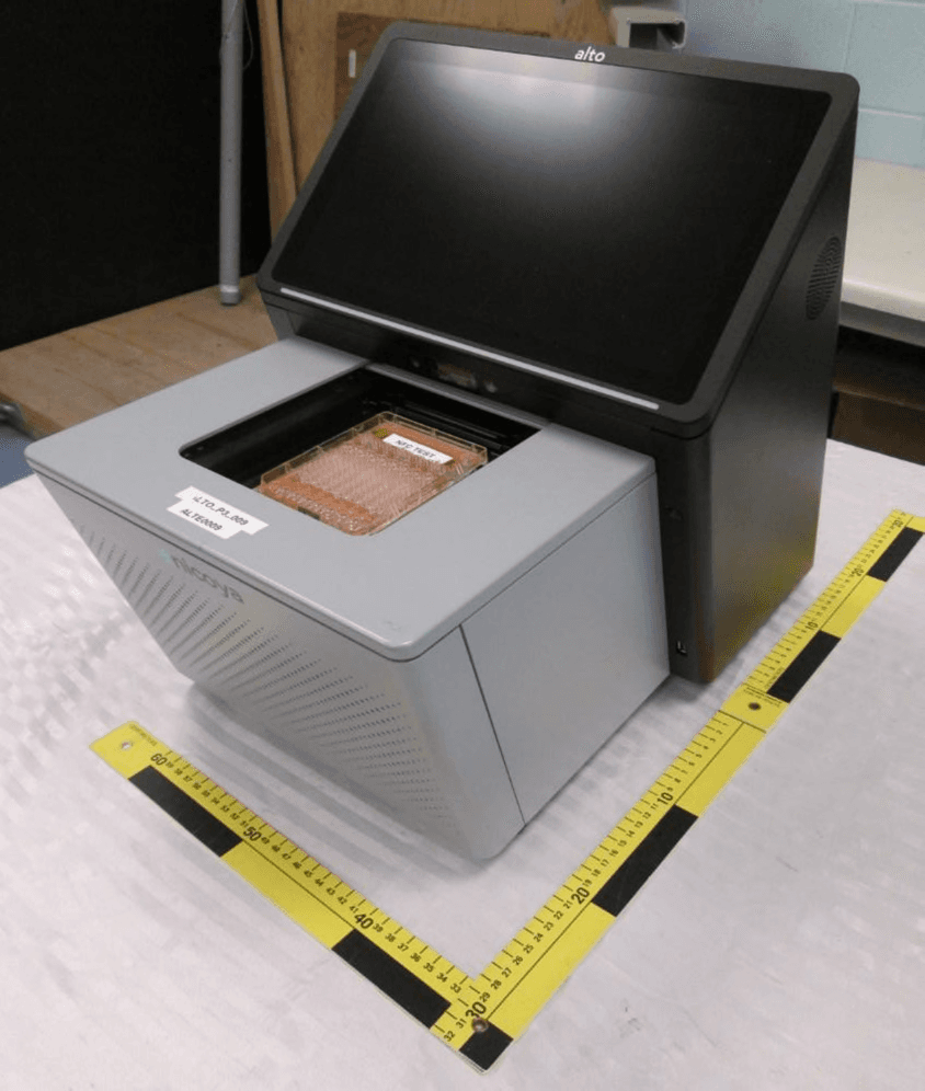
Click to zoom
Application Details
- Equipment Class
- DXX - Part 15 Low Power Communication Device Transmitter
- Date of Grant
- Jul 29, 2021
- Application Purpose
- Original Equipment
- Date of Application
- Jul 28, 2021
- Equipment Note
- SPR Lab Instrument
- Frequency Range
- 13.56000000 - 13.56000000
- Company
- Nicoya Lifesciences Inc.
- Country
- Canada
Documents & Files
Document Text
Text extracted from the exhibit documents filed with the FCC. Open a document above to read the original.
Users Manual
Operation Hardware Manual Version 1.1 Revision 2.0 Released: May 2021 [email protected] Alto Operation Manual V1.1 R2.0 2 Table of Contents 1.0 Introduction 5 1.1 Purpose 5 1.2 Pre-requisites 5 1.3 Important User Information 5 1.3.1 Intended Use 5 1.4 Regulatory Information 5 1.4.1 Manufacturer Information 5 1.4.2 Power and Temperature 6 1.4.3 Compliance 6 2.0 Safety Instructions 7 2.1 Safety Precautions 7 2.2 Disposal and Instrument Decommissioning 8 3.0 System Details 9 3.1 Alto Hardware 9 3.1.1 Instrument Display 9 3.1.2 Instrument Feature Locations 10 3.1.3 Other features 11 3.2 Alto Cartridge 12 3.2.1 Architecture of Alto Cartridge 12 3.2.2 Alto Cartridge Design 13 3.2.3 Types of Alto Cartridges 16 4.0 Getting started with Alto 17 4.1 Initial Equipment Setup Requirements 17 4.2 Standard Equipment Supplies 17 4.3 Unpacking the Alto Instrument 18 4.4 Removing the Shipping Plate 20 4.5.1 Leveling The Instrument 21 4.5.2 Optional: Securing Alto to a Lab Bench 22 4.5.2.1 Lab Space Requirements 22 4.5.2.2 Materials Provided 22 Alto Operation Manual V1.1 R2.0 3 4.5.2.3 Attaching The Table Mount Brackets 23 4.5.2.4 Mounting the Brackets to The Lab Bench 25 4.6 Hardware Setup 27 4.6.1 Alto Power Connection 27 4.6.2 Powering on The Alto 28 4.6.3 Accessories 29 4.7 Software Setup 30 4.7.1 Setting up a new user account on the User Portal 30 4.7.1.1 Overview of Nicoya User Portal Dashboard 30 4.7.2 Experiment Design on User Portal 34 4.7.2.1 Experiment: Assay Setup 36 4.7.2.2 Method: Assay Activities 40 4.7.2.3 Sample Identity 45 4.7.2.4 Build 48 5.0 Standard Operating Procedures 50 5.1 Starting the Instrument 50 5.2 Setup an Internet Connection 50 5.2.1 Option 1: Setup an Ethernet Cable Connection 50 5.2.2 Option 2: Connect to a Wireless Network 50 5.3 Alto Control Software Login 51 5.4 Optical Calibration with Optics Service Cartridge 52 5.4.1 When to use the OSC 53 5.4.2 OSC Replacement parts 53 5.4.3 Materials needed for Optical Calibration 53 5.4.4 Optics Service Wipe Installation 54 5.4.4.1 OSC Wipe Installation 54 5.4.4.2 Installing the OSC into the Alto 55 5.4.5 Optics Calibration Protocol 55 5.4.6 Disassembling the OSC Slider 57 5.5 Diagnostic Test with the QC Cartridge 57 5.5.1 When to use the QC Cartridge 57 5.5.2 Adding Optics Gel to the QC Cartridge 58 5.5.2.1 Materials Needed 58 Alto Operation Manual V1.1 R2.0 4 5.5.2.2 Gel Application Instructions 58 5.5.3 Diagnostics Test Protocol 59 5.6 Experimental Setup 62 5.6.1 Required Materials 62 5.6.2 Loading Your Experiment 63 5.6.3 Unpacking the Cartridge 64 5.6.4 Loading the Cartridge 64 5.6.5 Loading the Cartridge Fluid 66 5.6.6 Loading Samples 69 5.6.6.1 Reverse pipetting for samples 71 5.6.6.2 Using the pipette guide 71 5.7 Running the Experiment 73 5.7.1 Visualizing by Activities 75 5.7.2 Visualizing by Cycles 76 5.7.2.1 Experiment Pause 77 5.7.2.2 Experiment Abort 77 5.7.3 Cartridge Removal and Disposal 78 5.8 Instrument Processes 79 5.8.1 Instrument Shutdown 79 5.8.2 Instrument User Logout 80 5.8.3 About and Contact Support 80 5.9 Data Output Files 81 Alto Operation Manual V1.1 R2.0 5 1.0 Introduction 1.1 Purpose The Operating Manual provides information and instructions on safe and recommended usage of Alto. 1.2 Pre-requisites To ensure Alto is operated safely and according to intended purpose, the following prerequisites must be completed: ● Read the Safety Instructions carefully. ● Install the system according to the instructions in “Getting Started with Alto”. ● Understand the Standard Operating Procedures to perform experiments. ● Be familiar with general laboratory equipment and handling of biological materials. 1.3 Important User Information The Safety Instructions in this manual must be read by all users prior to installing, using or interacting with the Alto instrument. The Alto system should not be operated in any other capacity other than as described in this manual. Operating the system outside of the Safety Instructions could expose users to hazards that could lead to personal injury or damage to the instrument. 1.3.1 Intended Use Alto is a surface plasmon resonance (SPR) system that measures molecular interactions in laboratory-based research. The real-time label-free analysis is intended for research use only and should not be used for diagnostic, clinical or in vitro procedures. Based on the number of molecules that can be experimented with, there is both a diverse and broad range of research that can be performed. The data collected is by no means suggestive or instructive, and any decision made based on the resulting data is exclusively the responsibility of the user. Any actions taken based on the resulting data are not considered to be based on Nicoya’s instructions and/or use specifications. A qualified team of application scientists is made available upon purchase of a Nicoya product and consultation should be pursued prior to conducting any experiment where there is doubt on whether it would qualify as “intended use.” 1.4 Regulatory Information 1.4.1 Manufacturer Information The Alto system is manufactured by Nicoya and the address for the manufacturer is provided below: Alto Operation Manual V1.1 R2.0 6 Nicoya Lifesciences 29 King St E Unit B Kitchener, Ontario, N2G 2K4 Canada Phone: +1 877-673-6777 1.4.2 Power and Temperature Input Power: 100-240VAC, 50-60Hz, 450W Operating temperature range is 15-35 degrees Celsius. 1.4.3 Compliance Note: This equipment has been tested and found to comply with the limits for a Class A digital device, pursuant to part 15 of the FCC Rules. Operation is subject to the following two conditions: (1) This device may not cause harmful interference, and (2) this device must accept any interference received, including interference that may cause undesired operation. These limits are designed to provide reasonable protection against harmful interference when the equipment is operated in a commercial environment. This equipment generates, uses, and can radiate radio frequency …
Text truncated - open the document above for the full version.
Cover Letter(s)
Date: May, 17 2021 Subject: FCC Confidentiality Request Federal Communications Commission Equipment Authorization Branch 7435 Oakland Mills Road Columbia, MD 21046 FCC ID: 2AYVDALTO Pursuant to Sections 0.457(d)(1)(ii) and 0.459 of the Commission’s Rules, Nicoya Lifesciences Inc. hereby requests permanent confidential treatment of information accompanying this application as outlined below: Schematics Bill of Materials/Parts List Block Diagrams Theory of Operation/Operation Description Nicoya Lifesciences Inc. also hereby requests short-term confidential treatment of information accompanying this application as outlined below for a period of period of 120 days: Internal Photos External Photos User Manual Test Set-up Photographs The above materials contain trade secrets and proprietary information not customarily released to the public. The public disclosure of these matters might be harmful to the Applicant and provide unjustified benefits to its competitors. The Applicant understands that pursuant to Rule 0.457(d)(1)(ii), disclosure of this Application and all accompanying materials will not be made before the date of the Grant for this Application. Thank you, Signature____________________________________ Name____Ryan Denomme______________________ Title_____CEO________________________________ Date_____May 17th. 2021____________________
External Photos
EUT – External view 1 EUT – External view 2
ID Label/Location Info
Alto Instrument v1.1 Label Specification D2ocument Revision: R0 Alto Unit Label Size: 100x20mm Label Location Specifications The following specification were received from TUV and decided on internally Label partAlto specsNotes Product/Company logo Surface Plasmon Resonance Instrument N/A The label on the back of the instrument requires information for compliance purposes. Model Number1.1N/A Serial NumberALTXYYYY8 character alphanumeric string ALT - stands for Alto X - 1 for start of Pilot onward YYYY - accounts for 9999 units Note: If a minor change is made and X goes from 1 2, the YYYY sequence continues from the last built ALT1 Input100-240VAC 50-60Hz 450W FCC ID2AYVDALTO ICXXXXX-YYYY ex. 27039-ALTO XXXXX - ISED Company number YYYY - UPN (unique product number) ContainsFCC ID: RYK-WPEQ261ACNIBT IC: 6158A-EQ261ACNIBT This is for the WiFi module inside the instrument For Research Use Only Mfg yearYYYY ex. 2021 Made in _______Designed in Canada Made in Singapore From an international trade perspective, we can't put Made in Canada, we don't do enough to the unit to classify for a tariff shift. (an example of a tariff shift would be important a tire, frame and seat, then assembling into a bike. The assembling count as a tariff shift, changing components into a bike, so it can then be labelled Made in Canada, even though it's 100% imported) CE Mark for European Union NRTL Mark for Canada and United States EAC Mark for Russia Canada ICCAN ICES-3(A)/NMB-3(A) Revision History RevisionDescriptionAuthor R01Addition of Certifications (FCC, ID, CE mark, TUV mark and EAC mark) (from V1.0) @ Soleil Grisé R02Addition of “Contains” information, updated label @ Tamara Bugarski
Internal Photos
EUT – Internal view 1 Panels opened, front EUT – Internal view 2 Panels opened, left side EUT – Internal view 3 Panels opened, right side EUT – Internal view 4 Panels opened, back EUT – Internal view 5 Panels opened, front close-up NFC board is within this compartment, connected via USB cable. EUT – Internal view 6 Panels opened, front, monitor detached EUT – Internal view 7 Panels opened, left side, monitor detached NFC board is within this compartment EUT – Internal view 8 NFC board compartment close-up EUT – Internal view 9 NFC board within compartment EUT – Internal view 10 NFC board, side 1 EUT – Internal view 11 NFC board, side 2
RF Exposure Info
Report File #: 7169009718R-MPE-000 © TÜV SÜD Canada Inc. This test report shall not be reproduced except in full, without written approval of TÜV SÜD Canada Inc Exhibit: RF Exposure – FCC Colocation of NFC + Certified Module FCC ID: 2AYVDALTO IC: 27039-ALTO Contains Certified Module: FCC ID: RYK-WPEQ261ACNIBT IC: 6158A-EQ261ACNIBT Client Nicoya Life Sciences Product Alto Standard(s) FCC 2.1091 and FCC 1.1310 Page 2 of 5 Report Issued: 7/26/2021 Report File #: 7169009718R-FCCMPE-000 © TÜV SÜD Canada Inc. This test report shall not be reproduced except in full, without written approval of TÜV SÜD Canada Inc. RF Exposure – FCC The device is a mobile device intended to generally be used in such a way that a separation distance of at least 20 centimeters is normally maintained between the transmitter's radiating structure and the body of the user or nearby persons. The unit is considered a mobile device. The EUT is an RFID NFC transmitter operating at 13.56 MHz. The EUT contains a certified transmitter module with WiFi and BT (Bluetooth) capabilities operating at 2.4 GHz and 5 GHz. The NFC can operate simultaneously with the WiFi/BT module. The WiFi/BT module can operate with either 2.4 GHz WiFi + BT, or 5 GHz WiFi + BT. Simultaneous operation of the transmitters is possible. Therefore, antenna co-location testing is also evaluated. Radio Frequency Exposure Evaluation: Mobile Devices Mobile devices shall be evaluated for RF radiation exposure according to the provisions of FCC 2.1091 and the MPE guidelines identified in FCC 1.1310. As per FCC §1.1310 Table 1(ii), the limit for Maximum Permissible Exposure (MPE) for radiofrequency electromagnetic fields for General Population/Uncontrolled Exposure is the following: NFC Transmitter In the frequency range of 1.34 to 30 MHz: 180/f 2 mW/cm 2 Where f = frequency in MHz. WiFi Transmitter In the frequency range of 1500 MHz to 100 GHz: 1.0 mW/cm 2 . Client Nicoya Life Sciences Product Alto Standard(s) FCC 2.1091 and FCC 1.1310 Page 3 of 5 Report Issued: 7/26/2021 Report File #: 7169009718R-FCCMPE-000 © TÜV SÜD Canada Inc. This test report shall not be reproduced except in full, without written approval of TÜV SÜD Canada Inc. Therefore, the limits for this device are as follows: MPE Limits Transmitter Frequency Limit NFC 13.56 MHz 0.979 mW/cm 2 BT 2.4 GHz 1.0 mW/cm2 WiFi 2.4 GHz, 5 GHz 1.0 mW/cm2 The power density formula is given by: P d = (EIRP) / (4πR 2 ) Where, P d = Power density in mW/cm 2 EIRP = Equivalent Isotropic Radiated Power = (Output Power)*(Antenna Gain) π = 3.1416 R = Separation distance in cm MPE of 13.56MHz Transmitter The 13.56MHz transmitter has a maximum radiated output power of 51.83 dBμV (at 3m) which equals to an EIRP of (51.83 – 95.2) = -43.37 dBm or 0.00004603 mW. For a distance of 20 cm, the power density is: P d = (0.00004603 mW) / (4 * 3.1416 * (20cm) 2 ) P d = 0.00000000916 mW/cm 2 The device passes the requirement. The calculated power density of 0.00000000916 mW/cm 2 is below the 0.979 mW/cm 2 limit. Client Nicoya Life Sciences Product Alto Standard(s) FCC 2.1091 and FCC 1.1310 Page 4 of 5 Report Issued: 7/26/2021 Report File #: 7169009718R-FCCMPE-000 © TÜV SÜD Canada Inc. This test report shall not be reproduced except in full, without written approval of TÜV SÜD Canada Inc. MPE of WiFi Transmitter Per its FCC filing documents, at a 20 cm distance: The 2.4 GHz WiFi transmitter has a max power density of: P d = 0.088 mW/cm 2 The 5 GHz WiFi transmitter has a max power density of: P d = 0.076 mW/cm 2 MPE of BT Transmitter Per its FCC filing documents, at a 20 cm distance: The BT transmitter has a max power density of: P d = 0.001 mW/cm 2 Client Nicoya Life Sciences Product Alto Standard(s) FCC 2.1091 and FCC 1.1310 Page 5 of 5 Report Issued: 7/26/2021 Report File #: 7169009718R-FCCMPE-000 © TÜV SÜD Canada Inc. This test report shall not be reproduced except in full, without written approval of TÜV SÜD Canada Inc. Calculations for Simultaneous Transmission Device As per FCC KDB447498 7.2: Simultaneous transmission MPE test exclusion applies when the sum of the MPE ratios for all simultaneous transmitting antennas incorporated in a host device, based on the calculated/estimated, numerically modeled or measured field strengths or power density, is ≤ 1.0. MPE ratio = Ratio of power density to MPE limit at the test frequency = P d / (MPE limit) MPE ratio for NFC transmitter = 0.00000000916 mW/cm 2 / 0.979 mW/cm 2 = 0.00000000936 MPE ratio for 2.4 GHz WiFi transmitter = 0.088 mW/cm 2 / 1 mW/cm 2 = 0.088 MPE ratio for 5 GHz WiFi transmitter = 0.076 mW/cm 2 / 1 mW/cm 2 = 0.076 MPE ratio for 2.4 GHz BT transmitter = 0.001 mW/cm 2 / 1 mW/cm 2 = 0.001 Sum of MPE ratios for NFC + 2.4 GHz WiFi + 2.4 GHz BT = 0.00000000936 + 0.088 + 0.001 = 0.08900001 < 1.0 Sum of MPE ratios for NFC + 5 GHz WiFi + 2.4 GHz BT = 0.00000000936 + 0.076 + 0.001 = 0.07700001 < 1.0 Result MPE test exclusion applies for all simultaneous transmission configurations.
Test Report
Registration # 6844A-3 Testing Laboratory Certificate #2955.02 R-4023, G-506 C-4498, T-1246 Registration # CA6844 Page 1 of 60 Report Issued: 7/26/2021 Report File #: 7169009718R-FCC-000 © TÜV SÜD Canada Inc. This test report shall not be reproduced except in full, without written approval of TÜV SÜD Canada Inc FCC 15 225 Rev1 RF Test Report As per RSS-210 Annex B.6, Issue 10:2019 & FCC Part 15 Subpart 15.225 Low Power Licence Exempt Radio Communication Devices Intentional Radiators on the Alto Issued by: TÜV SÜD Canada Inc. 11 Gordon Collins Dr, Gormley, ON, L0H 1G0 Canada Ph: (905) 883-7255 Testing produced for See Appendix A for full client & EUT details. Prepared by: Raymond Lee Au, Project Engineer Reviewed by: Amir Emami, Project Engineer Client Nicoya Life Sciences Product Alto Standard(s) RSS 210 Annex B.6, Issue 10:2019 FCC Part 15 Subpart 15.225 Page 2 of 60 Report Issued: 7/26/2021 Report File #: 7169009718R-FCC-000 © TÜV SÜD Canada Inc. This test report shall not be reproduced except in full, without written approval of TÜV SÜD Canada Inc Table of Contents Table of Contents ................................................................................................................... 2 Report Scope .......................................................................................................................... 3 Summary ................................................................................................................................ 4 Test Results Summary ....................................................................................................... 5 Notes, Justifications, or Deviations ................................................................................... 6 Sample Calculation(s) ........................................................................................................ 7 Applicable Standards, Specifications and Methods ............................................................... 8 Document Revision Status ..................................................................................................... 9 Definitions and Acronyms ................................................................................................... 10 Testing Facility .................................................................................................................... 11 Calibrations and Accreditations ....................................................................................... 11 Testing Environmental Conditions and Dates ................................................................. 12 Detailed Test Results Section .............................................................................................. 13 Radiated Emission Field Strength .................................................................................... 14 Transmitter Spurious Radiated Emissions ....................................................................... 25 Carrier Frequency Stability .............................................................................................. 46 Power Line Conducted Emissions ................................................................................... 49 20dB and 99% Occupied Bandwidth ............................................................................... 55 Appendix A – EUT Summary .............................................................................................. 59 Client Nicoya Life Sciences Product Alto Standard(s) RSS 210 Annex B.6, Issue 10:2019 FCC Part 15 Subpart 15.225 Page 3 of 60 Report Issued: 7/26/2021 Report File #: 7169009718R-FCC-000 © TÜV SÜD Canada Inc. This test report shall not be reproduced except in full, without written approval of TÜV SÜD Canada Inc Report Scope This report addresses the EMC verification testing and test results of the Alto unit from Nicoya Lifesciences Inc. This unit is herein referred to as EUT (Equipment Under Test). The EUT was tested for compliance against the following standards: RSS-210 Annex B.6, Issue 10:2019, FCC Part 15 Subpart C 15.225 Test procedures, results, justifications, and engineering considerations, if any, follow later in this report. This report does not imply product endorsement by any government, accreditation agency, or TÜV SÜD Canada Inc. Opinions or interpretations expressed in this report, if any, are outside the scope of TÜV SÜD Canada Inc accreditations. Any opinions expressed do not necessarily reflect the opinions of TÜV SÜD Canada Inc, unless otherwise stated. Client Nicoya Life Sciences Product Alto Standard(s) RSS 210 Annex B.6, Issue 10:2019 FCC Part 15 Subpart 15.225 Page 4 of 60 Report Issued: 7/26/2021 Report File #: 7169009718R-FCC-000 © TÜV SÜD Canada Inc. This test report shall not be reproduced except in full, without written approval of TÜV SÜD Canada Inc Summary The results contained in this report relate only to the item(s) tested. EUT Model: ALTO EUT FCC Certification #, FCC ID: 2AYVDALTO ISED Certification #, IC: 27039-ALTO EUT passed all tests performed Yes Tests conducted by Raymond Lee Au Report reviewed by Amir Emami For testing dates, see "Testing Environmental Conditions and Dates". Client Nicoya Life Sciences Product Alto Standard(s) RSS 210 Annex B.6, Issue 10:2019 FCC Part 15 Subpart 15.225 Page 5 of 60 Report Issued: 7/26/2021 Report File #: 7169009718R-FCC-000 © TÜV SÜD Canada Inc. This test report shall not be reproduced except in full, without written approval of TÜV SÜD Canada Inc Test Results Summary Standard/Method Description Class/Limit Result FCC 15.203 Antenna Requirement Unique Pass α FCC 15.225 (a), (b), (c) RSS-210 B.6 a. i, ii, iii. Operation within the band 13.110-14.010 MHz (Field Strength) Quasi-Peak Average Pass FCC 15.225 (d) FCC 15.209 RSS-210 B.6 a. iv RSS-GEN (Tables 5 & 6) Transmitter Spurious Radiated Emissions Quasi-Peak Average Pass FCC 15.225 (e) RSS-210 B.6 b. RSS-Gen 6.11 Operation within the band 13.110-14.010 MHz (Frequenc…
Text truncated - open the document above for the full version.
Test Setup Photos
Test setup photo 1 Radiated measurements, 9 kHz – 30 MHz Test setup photo 2 Radiated measurements, 30 MHz – 1 GHz Test setup photo 3 Radiated measurements, 1 GHz – 6 GHz Test setup photo 4 Radiated measurements, 6 GHz – 10 GHz Test setup photo 5 Radiated measurements, 10 GHz – 18 GHz Test setup photo 6 Radiated measurements, 18 GHz – 26.5 GHz Test setup photo 7 Radiated measurements, 26.5 GHz – 40 GHz Test setup photo 8 Power line conducted emissions measurements Test setup photo 9 Frequency Stability at Extreme Temperatures Test setup photo 10 Frequency Stability at Extreme Voltages
Contact Information
Applicant
Ryan Denomme(CEO)
Test Firm
TUV SUD CANADA (Gormley)William (Mac) Elliott
[email protected]813-284-2736
Technical Specifications
| # | Rule Parts | Frequency Range | Power Output |
|---|---|---|---|
| 1 | 15C | 13.56 MHz - 13.56 MHz | - |