2AYX6-ROLORolo BLE module
Cricut, Inc.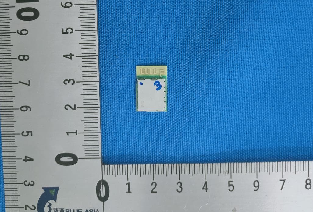
Click to zoom
Application Details
- Equipment Class
- DTS - Digital Transmission System
- Date of Grant
- Apr 13, 2021
- Application Purpose
- Original Equipment
- Date of Application
- Apr 12, 2021
- Equipment Note
- Rolo BLE module
- Frequency Range
- 2402.00000000 - 2480.00000000
- Company
- Cricut, Inc.
- Country
- United States
Documents & Files
Document Text
Text extracted from the exhibit documents filed with the FCC. Open a document above to read the original.
Users Manual
RoloBluetooth LE Module User Guide March 2021 C O N F I D E N T I A L 2 • Rolo Key Feature • Bluetooth LE module had been implemented with Telink SoC TLSR8251F512ET48. • Embedded with BLE transceiver, working in worldwide 2.4GHz ISM band, ANT mode. • Compliant to BT LE class 2 device. Max emitted power of 4dbM, typ 10 M RF range. • Provide 26 GPIO interfacing pads which can support various I/O purposes such as simple LCD displays, ADC for temperature and control, timer control, USB and etc by through specific embedded SoC firmware. • Operating Voltage: 3.3V. • To be used as BT RF transceiver and SoC for Cricut Inc. Easy Press Series product. • Not for Sale as off-of-shelf product for any other parties. • Photo Introduction and Key Feature C O N F I D E N T I A L Schematic 3 Confidential C O N F I D E N T I A L PCB Specific Drawing 4 C O N F I D E N T I A L PCB Specific Drawing –For RF metal shield can design ref 5 C O N F I D E N T I A L FCC St at ement 6 FCC standards: FCC CFR Title 47 Part 15 Subpart C Section 15.247 PCB antenna , Antenna gain 0dBi This device complies with part 15 of the FCC Rules. Operation is subject to the following two conditions: (1) This device may not cause harmful interference, and (2) this device must accept any interference received, including interference that may cause undesired operation. Any Changes or modifications not expressly approved by the party responsible for compliance could void the user's authority to operate the equipment. Note: This equipment has been tested and found to comply with the limits for a Class B digital device, pursuant to part 15 of the FCC Rules. These limits are designed to provide reasonable protection against harmful interference in a residential installation. This equipment generates, uses and can radiate radio frequency energy and, if not installed and used in accordance with the instructions, may cause harmful interference to radio communications. However, there is no guarantee that interference will not occur in a particular installation. If this equipment does cause harmful interference to radio or television reception, which can be determined by turning the equipment off and on, the user is encouraged to try to correct the interference by one or more of the following measures: —Reorient or relocate the receiving antenna. —Increase the separation between the equipment and receiver. —Connect the equipment into an outlet on a circuit different from that to which the receiver is connected. —Consult the dealer or an experienced radio/TV technician for help. FCC Radiation Exposure Statement This modular complies with FCC RF radiation exposure limits set forth for an uncontrolled environment. This transmitter must not be co-located or operating in conjunction with any other antenna or transmitter. If the FCC identification number is not visible when the module is installed inside another device, then the outside of the device into which the module is installed must also display a label referring to the enclosed module. This exterior label can use wording such as the following: “Contains Transmitter Module FCC ID: 2AYX6-ROLO Or Contains FCC ID: 2AYX6-ROLO ” When the module is installed inside another device, the user manual of the host must contain below warning statements; 1. This device complies with Part 15 of the FCC Rules. Operation is subject to the following two conditions: (1) This device may not cause harmful interference; (2) This device must accept any interference received, including interference that may cause undesired operation. Note: This equipment has been tested and found to comply with the limits for a Class B digital device, pursuant to part 15 of the FCC Rules. These limits are designed to provide reasonable protection against harmful interference in a residential installation. This equipment generates, uses and can radiate radio frequency energy and, if not installed and used in accordance with the instructions, may cause harmful interference to radio communications. However, there is no guarantee that interference will not occur in a particular installation. If this equipment does cause harmful interference to radio or television reception, which can be determined by turning the equipment off and on, the user is encouraged to try to correct the interference by one or more of the following measures: —Reorient or relocate the receiving antenna. —Increase the separation between the equipment and receiver. —Connect the equipment into an outlet on a circuit different from that to which the receiver is connected. —Consult the dealer or an experienced radio/TV technician for help. 2. Changes or modifications not expressly approved by the party responsible for compliance could void the user's authority to operate the equipment. The devices must be installed and used in strict accordance with the manufacturer's instructions as described in the user documentation that comes with the product. Any company of the host device which install this modular with modular approval should perform the test of radiated & conducted emission and spurious emission, etc. according to FCC part 15C : 15.247 and 15.209 & 15.207 ,15B Class B requirement, Only if the test result comply with FCC part 15C : 15.247 and 15.209 & 15.207 ,15B Class B requirement, then the host can be sold legally.
Attestation Statements
CompliancelistINTEGRATIONINSTRUCTIONSfor996369D03OEMtheand996369D03OEMby Sections2.2through2.10. RequirementYesN/AComment 2.2ListofapplicableFCCrules ListtheFCCrulesthatareapplicabletothe modulartransmitter.Thesearetherulesthat specificallyestablishthebandsofoperation, thepower,spuriousemissions,andoperating fundamentalfrequencies.DONOTlist compliancetounintentional-radiatorrules (Part15SubpartB)sincethatisnota conditionofamodulegrantthatisextended toahostmanufacturer.SeealsoSection2.10 belowconcerningtheneedtonotifyhost manufacturersthatfurthertestingis required.3 YESRefertoinstruction FCCstandards:FCCCFRTitle47Part15 SubpartCSection15.247 2.3Summarizethespecificoperationaluse conditions Describeuseconditionsthatareapplicableto themodulartransmitter,includingfor exampleanylimitsonantennas,etc.For example,ifpoint-to-pointantennasareused thatrequirereductioninpoweror compensationforcableloss,thenthis informationmustbeintheinstructions.Ifthe useconditionlimitationsextendto professionalusers,theninstructionsmust statethatthisinformationalsoextendstothe hostmanufacturer’sinstructionmanual.In addition,certaininformationmayalsobe needed,suchaspeakgainperfrequencyband andminimumgain,specificallyformaster devicesin5GHzDFSbands. YESRefertoinstruction PCBantenna,Antennagain0dBi 2.4Limitedmoduleprocedures Ifamodulartransmitterisapprovedasa “limitedmodule,”thenthemodule manufacturerisresponsibleforapprovingthe hostenvironmentthatthelimitedmoduleis usedwith.Themanufacturerofalimited modulemustdescribe,bothinthefilingandin theinstallationinstructions,thealternative meansthatthelimitedmodulemanufacturer usestoverifythatthehostmeetsthe necessaryrequirementstosatisfythemodule limitingconditions. Alimitedmodulemanufacturerhasthe flexibilitytodefineitsalternativemethodto addresstheconditionsthatlimittheinitial N/ANotapplicable approval,suchas:shielding,minimum signalingamplitude,buffered modulation/datainputs,orpowersupply regulation.Thealternativemethodcould includethatthelimitedmodulemanufacturer reviewsdetailedtestdataorhostdesigns priortogivingthehostmanufacturer approval. Thislimitedmoduleprocedureisalso applicableforRFexposureevaluationwhenit isnecessarytodemonstratecomplianceina specifichost.Themodulemanufacturermust statehowcontroloftheproductintowhich themodulartransmitterwillbeinstalledwill bemaintainedsuchthatfullcomplianceofthe productisalwaysensured.Foradditional hostsotherthanthespecifichostoriginally grantedwithalimitedmodule,aClassII permissivechangeisrequiredonthemodule granttoregistertheadditionalhostasa specifichostalsoapprovedwiththemodule. 2.5Traceantennadesigns Foramodulartransmitterwithtraceantenna designs,seetheguidanceinQuestion11of KDBPublication996369D02FAQ–Modules forMicro-StripAntennasandtraces.The integrationinformationshallincludeforthe TCBreviewtheintegrationinstructionsforthe followingaspects:layoutoftracedesign,parts list(BOM),antenna,connectors,andisolation requirements.4 a)Informationthatincludespermitted variances(e.g.,traceboundarylimits, thickness,length,width,shape(s),dielectric constant,andimpedanceasapplicablefor eachtypeofantenna); b)Eachdesignshallbeconsideredadifferent type(e.g.,antennalengthinmultiple(s)of frequency,thewavelength,andantenna shape(tracesinphase)canaffectantenna gainandmustbeconsidered); c)Theparametersshallbeprovidedina mannerpermittinghostmanufacturersto designtheprintedcircuit(PC)boardlayout; d)Appropriatepartsbymanufacturerand specifications; e)Testproceduresfordesignverification;and N/ANotapplicable f)Productiontestproceduresforensuring compliance. Themodulegranteeshallprovideanoticethat anydeviation(s)fromthedefinedparameters oftheantennatrace,asdescribedbythe instructions,requirethatthehostproduct manufacturermustnotifythemodulegrantee thattheywishtochangetheantennatrace design.Inthiscase,aClassIIpermissive changeapplicationisrequiredtobefiledby thegrantee,orthehostmanufacturercan takeresponsibilitythroughthechangeinFCC ID(newapplication)procedurefollowedbya ClassIIpermissivechangeapplication. 2.6RFexposureconsiderations Itisessentialformodulegranteestoclearly andexplicitlystatetheRFexposureconditions thatpermitahostproductmanufacturerto usethemodule.Twotypesofinstructionsare requiredforRFexposureinformation:(1)to thehostproductmanufacturer,todefinethe applicationconditions(mobile,portable–xx cmfromaperson’sbody);and(2)additional textneededforthehostproduct manufacturertoprovidetoendusersintheir end-productmanuals.IfRFexposure statementsanduseconditionsarenot provided,thenthehostproductmanufacturer isrequiredtotakeresponsibilityofthe modulethroughachangeinFCCID(new application). YESRefertoinstruction ThismodularcomplieswithFCCRF radiationexposurelimitssetforthforan uncontrolledenvironment.Thistransmitter mustnotbeco-locatedoroperatingin conjunctionwithanyotherantennaor transmitter. 2.7Antennas Alistofantennasincludedintheapplication forcertificationmustbeprovidedinthe instructions.Formodulartransmitters approvedaslimitedmodules,allapplicable professionalinstallerinstructionsmustbe includedaspartoftheinformationtothehost productmanufacturer.Theantennalistshall alsoidentifytheantennatypes(monopole, PIFA,dipole,etc.(notethatforexamplean “omni-directionalantenna”isnotconsidered tobeaspecific“antennatype”)). Forsituationswherethehostproduct manufacturerisresponsibleforanexternal connector,forexamplewithanRFpinand YESRefertoinstruction PCBantenna,Antennagain0dBi antennatracedesign,theintegration instructionsshallinformtheinstallerthat uniqueantennaconnectormustbeusedon thePart15authorizedtransmittersusedin thehostproduct.Themodulemanufacturers shallprovidealistofacceptableunique connectors. 2.8Labelandcomplianceinformation Granteesareresponsibleforthecontinued complianceoftheirmodulestotheFCCrules. Thisincludesadvisinghostproduct manufacturersthattheyneedtoprovidea physicalore-labelstating“ContainsFCCID” withtheirfinishedproduct.SeeGuidelinesfor LabelingandUserInformationforRFDevices– KDBPublication784748. YESRefertoinstruction IftheFCCidentific…
Text truncated - open the document above for the full version.
Cover Letter(s)
DATE : Equipment Autorisation Division Federal Communications Commission 7435 Oakland Mills Road Columbia, MD 21046 FCC ID: 2AYX6‐ROLO Product Name:Rolo BLE module Request for Short-Term Confidentiality Pursuant to Sections 0.457 and 0.459 of the commission rules, and in accordance with the FCC Public notice dated June 15, 2004 (DA 04-1705), we hereby request short-term confidentiality for the following items prior to marketing the device.: Test Setup Photos External Photos Internal Photos User Manual The applicant requests the exhibits selected above as short term confidential be withheld from public view for a period of 45 days from the date of the Grant of Equipment Authorization and prior to marketing. This is to avoid premature release of sensitive information prior to marketing or release of the product to the public. <Signature> Name Shajee Siddiqui Title Sr. Director, Product Safety & Compliance Company Cricut, Inc.
Cover Letter(s)
1 March 26, 2021 Equipment Authorization Division Federal Communications Commission 7435 Oakland Mills Road Columbia, MD 21046 FCC ID:__2AYX6‐ROLO Product Name: Rolo BLE module Request For Confidentiality Pursuant to Sections 0.457 and 0.459 of the commission’s rules, we, Cricut Inc., hereby request that the following documents, related to our products, be held confidential: Block Diagrams Schematics Operational Description These materials contain trade secrets and proprietary information and are not to be released to the public. The public disclosure of this information might be harmful to the company and could provide unwarranted access to company‐confidential information to our competitors. We appreciate your cooperation. Sincerely, Shajee Siddiqui Sr. Director, Product Safety & Compliance Cricut, Inc.
Cover Letter(s)
SingleModularapprovalDeclarationletter We , Cricut,Inc.applySinglemodularapprovalfor ProductName:RoloBLEmodule Model:V0038 FCCID:2AYX6-ROLO Accordingto996369D01ModuleEquipAuthGuidev01r04and15.212requirement: 1)Theradioelementsmusthavetheradiofrequencycircuitryshielded.Physical componentsandtuningcapacitor(s)maybelocatedexternaltotheshield,butmustbe onthemoduleassembly; Answer : Yes , Shielded 2)Themodulemusthavebufferedmodulation/datainputstoensurethatthedevice willcomplywithPart15requirementswithanytypeofinputsignal; Answer : Yes ; Allinputstothemodulesarebufferedthroughlogicormicroprocessor inputs. 3)Themodulartransmittermusthaveitsownpowersupplyregulation. Answer : Yes ; Alowdropoutregulatorisusedformodularpowersupplyregulation. 4)Themodulemustcontainapermanentlyattachedantenna,orcontainaunique antennaconnector,andbemarketedandoperatedonlywithspecificantenna(s),per Sections15.203,15.204(b),15.204(c),15.212(a),2.929(b); Answer : Yes ; DeviceisequippedwithPCBantenna. (5)Themodulemustdemonstratecomplianceinastand-aloneconfiguration; Answer : Yes , distancebetweenmodularandallAEsarebiggerthan10cm , refer tosetupphoto. (6)ThemodulemustbelabeledwithitspermanentlyaffixedFCCIDlabel,orusean electronicdisplay(SeeKDBPublication784748aboutlabellingrequirements); Answer : Yes ; Themodularhasapermanentfixedlabel,andbelowstatementwas listedintheUserManual;ThehostdevicemustbelabeledtodisplaytheFCCIDof themodule“ContainsFCCID:2AYX6-ROLO” (7)Themodulemustcomplywithallspecificrulesapplicabletothetransmitter includingalltheconditionsprovidedintheintegrationinstructionsbythegrantee; Answer : Yes ; Themodulecomplywithallspecificrulesapplicabletothe transmitterincludingalltheconditionsprovidedintheintegrationinstructionsby thegrantee,Refertotestreportandusermanual. (8)ThemodulemustcomplywithRFexposurerequirements Answer : Yes ; TransmittermeetsMPEcalculationofKDB447498.RefertoMPE ReportsandRefertomodularinstallationmanual Pleasecontactmeifyouhaveanyfurtherquestions.Thanksforyourattention. BestRegards, Sincerely, ShajeeSiddiqui Sr.Director,ProductSafety&Compliance Cricut,Inc.
External Photos
Model No.: V0038
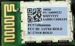
Internal Photos
Model No.: V0038
RF Exposure Info
RF Exposure Evaluation Statement Product Name: Rolo BLE module Model No.:V0038 FCC ID:2AYX6-ROLO 1.1 RF Exposure Compliance Requirement 1.1.1 Standard Requirement According to KDB447498D01 General RF Exposure Guidance v06 Standalone SAR test exclusion considerations Unless specifically required by the published RF exposure KDB procedures, standalone 1-g head or body and 10-g extremity SAR evaluation for general population exposure conditions, by measurement or numerical simulation, is not required when the corresponding SAR Exclusion Threshold condition, listed below, is satisfied. 1.1.2 Limits The 1-g and 10-g SAR test exclusion thresholds for 100 MHz to 6 GHz at test separation distances ≤ 50 mm are determined by: [(max. power of channel, including tune-up tolerance, mW)/(min. test separation distance, mm)] · [√f(GHz)] ≤ 3.0 for 1-g SAR and ≤ 7.5 for 10-g extremity SAR, where f(GHz) is the RF channel transmit frequency in GHz Power and distance are rounded to the nearest mW and mm before calculation 17 The result is rounded to one decimal place for comparison The test exclusions are applicable only when the minimum test separation distance is ≤ 50 mm and for transmission frequencies between 100 MHz and 6 GHz. When the minimum test separation distance is < 5 mm, a distance of 5 mm is applied to determine SAR test exclusion 1.1.3 EUT RF Exposure Operational Mode: BLE Channel Maximum Peak Conducted Output Power (dBm) Tune up tolerance (dB) Maximum tune-up Power Calculated value Exclusion threshold (dBm) (mW) 2402 1.1 ±1 2.1 1.62 0.50 3 2442 0.62 ±1 1.62 1.45 0.45 2480 -0.45 ±1 0.55 1.14 0.36 Conclusion: the calculated value ≤3.0, SAR is exempted.
Test Report
Page 1 of63 BlueAsia of Technical Services(Shenzhen) Co., Ltd. Add: Building C, No. 107, Shihuan Road, Shiyan Sub-District, Baoan District, Shenzhen, Guangdong Province, China Tel: +86-755-23059481 Email: [email protected] www.cblueasia.com TEST REPORT Product Name : Rolo BLE module Brand Mark : N/A Model No. : V0038 FCC ID : 2AYX6-ROLO Report Number : BLA-EMC-202101-A3801 Date of Sample Receipt : 2021/1/15 Date of Test : 2021/1/18 to 2021/2/1 Date of Issue : 2021/3/24 Test Standard : 47 CFR Part 15, Subpart C 15.247 Test Result : Pass Prepared for: Cricut Inc. 10855 South River Front Parkway, South Jordan, Utah, USA Prepared by: BlueAsia of Technical Services(Shenzhen) Co.,Ltd. Building C, No. 107, Shihuan Road, Shiyan Sub-District, Baoan District, Shenzhen, Guangdong Province, China TEL: +86-755-23059481 Compiled by: Review by: Approved by: Date: 2021/3/24 Report No.: BLA-EMC-202101-A3801 Page 2 of63 BlueAsia of Technical Services(Shenzhen) Co., Ltd. Tel: +86-755-23059481 Email: [email protected] www.cblueasia.com REPORT REVISE RECORD Version No. Date Description 00 2021/3/24 Original Report No.: BLA-EMC-202101-A3801 Page 3 of63 BlueAsia of Technical Services(Shenzhen) Co., Ltd. Tel: +86-755-23059481 Email: [email protected] www.cblueasia.com TABLE OF CONTENTS 1 TEST SUMMARY ........................................................................................................................................6 2 GENERAL INFORMATION .........................................................................................................................7 3 GENERAL DESCRIPTION OF E.U.T. .........................................................................................................7 4 TEST ENVIRONMENT ................................................................................................................................8 5 TEST MODE ................................................................................................................................................8 6 MEASUREMENT UNCERTAINTY ..............................................................................................................8 7 DESCRIPTION OF SUPPORT UNIT...........................................................................................................9 8 LABORATORY LOCATION .........................................................................................................................9 9 TEST INSTRUMENTS LIST ..................................................................................................................... 10 1 CONDUCTED EMISSIONS AT AC POWER LINE (150KHZ-30MHZ)..................................................... 13 1.1 LIMITS ................................................................................................................................................................... 13 1.2 BLOCK DIAGRAM OF TEST SETUP .......................................................................................................................... 13 1.3 PROCEDURE .......................................................................................................................................................... 13 1.4 TEST DATA .............................................................................................................................................................. 15 2 CONDUCTED BAND EDGES MEASUREMENT ..................................................................................... 17 2.1 LIMITS ................................................................................................................................................................... 17 2.2 BLOCK DIAGRAM OF TEST SETUP .......................................................................................................................... 17 2.3 TEST DATA .............................................................................................................................................................. 18 3 RADIATED SPURIOUS EMISSIONS ....................................................................................................... 19 3.1 LIMITS ................................................................................................................................................................... 19 3.2 BLOCK DIAGRAM OF TEST SETUP .......................................................................................................................... 20 3.3 PROCEDURE .......................................................................................................................................................... 20 3.4 TEST DATA .............................................................................................................................................................. 22 4 RADIATED EMISSIONS WHICH FALL IN THE RESTRICTED BANDS................................................. 30 4.1 LIMITS ................................................................................................................................................................... 30 4.2 BLOCK DIAGRAM OF TEST SETUP .......................................................................................................................... 31 4.3 PROCEDURE .......................................................................................................................................................... 31 4.4 TEST DATA .............................................................................................................................................................. 33 5 CONDUCTED SPURIOUS EMISSIONS .................................................................................................. 37 5.1 LIMITS ................................................................................................................................................................... 37 Report No.: BLA-EMC-202101-A3801 Pa…
Text truncated - open the document above for the full version.
Test Setup Photos
Model No.: V0038
Contact Information
Applicant
Shajee Siddiqui(Sr. Director)
Test Firm
BlueAsia of Technical Services (Shenzhen)Blue Zheng
[email protected]+86 755-23059481-815
Technical Specifications
| # | Rule Parts | Frequency Range | Power Output |
|---|---|---|---|
| 1 | 15C | 2.40 GHz - 2.48 GHz | 1.29 mW |
Other Applications from Cricut, Inc.
2AYX6-CSTP401
Jun 03, 2026StickerPix Print+Cut
Equipment Class
DSS - Part 15 Spread Spectrum Transmitter