2AYY5-AIDigital Transmission System
Soundwave Hearing, LLC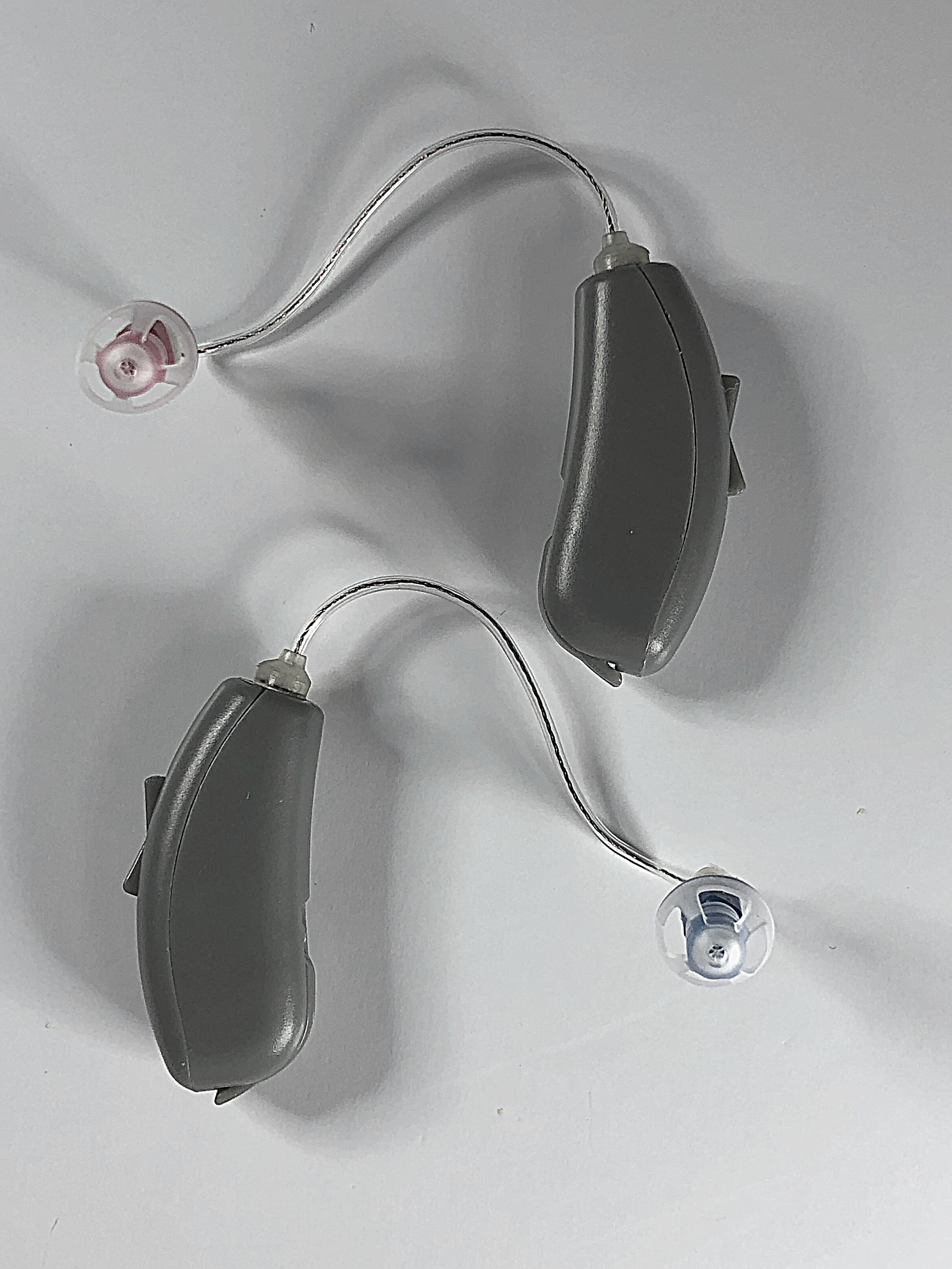
Click to zoom
Application Details
- Equipment Class
- DTS - Digital Transmission System
- Date of Grant
- Jul 14, 2022
- Application Purpose
- Original Equipment
- Date of Application
- Jul 13, 2022
- Equipment Note
- Digital Transmission System
- Frequency Range
- 2402.00000000 - 2480.00000000
- Company
- Soundwave Hearing, LLC
- Country
- United States
Documents & Files
Document Text
Text extracted from the exhibit documents filed with the FCC. Open a document above to read the original.
Users Manual
A USER MANUAL B CONGRATULATIONS! Please read this User Manual before programming your Sontro Hearing Aids. Soundwave Hearing recommends a 21-day trial period as this is, on average, how long it takes to adjust to new sounds from your hearing aids. Hearing new sounds may feel unusual at first, but most people find that they feel more comfortable using their hearing aids after 3 weeks of use. Get Back to Hearing, Get Back to Life with Sontro Hearing Aids. With Sontro TM Hearing Aids, you are back in control of the sounds around you, thanks to intuitive self- fitting software and advanced hearing technology. Let’s get started! C SUPPORT For assistance, please contact Soundwave Hearing: Call Customer Support at 833-367-HEAR (4327) Monday - Friday, 8:00 a.m. - 4:30 p.m., CST Email Customer Support at: [email protected] 24 hours a day, 7 days a week Your satisfaction is 100% guaranteed! If you’re not happy with your Sontro Hearing Aids , you can return them within 45 days for a 100% refund! We’ll be sad to see you go - and we’ll be here when you need us. GUARANTEE D TABLE OF CONTENTS [09.21.21] 01 Sontro TM Hearing Aids + otoTune TM App 06 Battery 12 Placement 16 Ear domes 22 Receivers/Measurement Tool 25 Volume button 28 Care 32 Wax Guards 35 Sound 43 Appendix 55 Warranty 1 With Sontro Hearing Aids, you are back in control of the sounds around you, thanks to self-fitting software and advanced hearing technology. Let’s get started! Test your hearing in 3-minutes and customize your settings with our intuitive otoTune™ app. You can download the otoTune app on your mobile phone at the Google Play or App Store. 2 Cleaning your ears Let’s face it, your ears make wax. Wax build up can get in the way of hearing. Your Sontro TM Hearing Aids have tiny parts on them, wax will clog them up. Even if your ears appear clean it’s a good idea to give them a quick swab before you put in your new Sontro Hearing Aids. 3 2 Soundwave Hearing Aids 1 Quick Start Guide 1 Receiver Measurement Tool 1 Thank you Card 1 Warranty Card 1 Happy / Not Happy Card 4 Size 312 Batteries 8 Ear Domes 1 Carrying Case 1 Cleaning Tool 2 Sport Locks Package Contents 4 Getting to Know your Sontro TM Hearing Aids LR MICROPHONE OPEN EAR DOME RECEIVER BATTERY DOOR VOLUME BUTTON 5 Soundwave manufactures the Sontro TM Hearing Aids as a paired set. When we manufacture hearing aids we program one as left, and one as right. The hearing aid with the blue tip receiver is the left hearing aid. The hearing aid with the red tip receiver is the right hearing aid. It is important that you insert the left hearing aid in your left ear and the right hearing aid in your right ear. Aside from using the color of the recievers to identify the left and right hearing aid, holding the hearing aids upright with control buttons facing you can also be used. The tips of receivers will face each other, when held in the correct hand. Please use caution when changing domes, wax guards or receivers to keep the left and right hearing aids with the correct colored receivers. Right and Left Hearing Aids 6 BATTERY 7 Our Sontro TM Hearing Aids are made to work with a Size 312 battery. Please only use this size. The battery door of the Sontro Hearing Aid is designed to have two functions, to power on/off and to change the battery. Battery Door Open the battery door to power off the hearing aid, when not in use. To open, gently pull battery door tab, located on the base of the hearing aid. Close the battery door to power on the hearing aid. When you open and close the battery door, thus turning your hearing aids off and on, they always return to the last setting. Powering the Hearing Aid On and Off WARNING: Batteries contain dangerous substances and should be disposed of carefully in the interest of your safety and for the environment. Also, keep batteries away from pets, children and persons with disabilities. If a battery is accidentally swallowed, seek medical attention immediately, or call the National Battery Hotline at 1-800-498-8666. Battery Warning 8 STEP 1: Remove brown adhesive tab on a new battery. Wait one (1) FULL minute for the battery to fully activate. NOTE: Remove excess adhesive film that occasionally adheres to the top of the battery. How to Insert the Battery STEP 2: Gently pull battery door tab located on the base of the hearing aid. Open door, insert a fresh 312 battery with the positive ‘+’ side facing up. STEP 3: To turn on your Sontro TM Hearing Aid, close the battery door. Your hearing aid will play a set of chimes to let you know the power is on. NOTE: Never force the battery door closed. If the battery door doesn’t close easily, then the battery may be improperly seated in the battery door, remove the battery and re-insert the battery before closing the door again. BATTERY DOOR 9 There are two ways to know that you have a low battery in your hearing aid. Your hearing aids will remind you by saying “low battery” when they have a low battery level. The otoTune app also allows you to visualize your battery life on the “Devices” screen. Low Battery Indicator • Only use new 312 batteries when replacing your batteries. • Always leave new batteries sealed in their original packages. • Do not remove the tab on your battery until you are ready to use it. • Do not use expired, unsealed, or corroded batteries. • Do not leave expired batteries in your Sontro TM Hearing Aids. • Open the battery door when not in use, especially at night to allow any excess moisture to evaporate and prolong the life of your hearing aids. • Store batteries at room temperature. • Store and discard batteries in places that cannot be reached by infants or children. Battery Tips 10 INDIVIDUAL HEARING LOSS: As hearing loss increases, more power is required to effectively amplify sounds. This increases the current needed from the battery and reduces battery life. In general, the more severe the hearing loss, the shorter the battery life. Also, hearing loss can vary from ear to e…
Text truncated - open the document above for the full version.
External Photos
EXTERNAL BEIGE SONTRO ™ HEARING AID C O N F I D E N T I A L 708.207-7021 hearsoundwave.com 619 Enterprise Drive, Suite 205 Oak Brook, IL 60523 CONTACT 990011-SWH.A2 CONFIDENTIAL 990011-SWH.A2 CONFIDENTIAL 990011-SWH.A2
External Photos
CONFIDENTIAL 990011-SWH.A2 EXTERNAL GREY SONTRO ™ HEARING AID C O N F I D E N T I A L 708.207-7021 hearsoundwave.com 619 Enterprise Drive, Suite 205 Oak Brook, IL 60523 CONTACT 990002-SWH.A2
External Photos
CONFIDENTIAL 990002-SWH.A2 CONFIDENTIAL 990002-SWH.A2
External Photos
CONFIDENTIAL 990002-SWH.A2
ID Label/Location Info
Side #4 Adjacent Length of Package Sleeve Side #5 Front of Package Sleeve Side #5 Back of Package Sleeve 708.207-7021 hearsoundwave.com 619 Enterprise Drive, Suite 205 Oak Brook, IL 60523 CONTACT INFO : Package Sleeve Layout Sleeve is 2 1/2 " w x 5 1/4 "long Sleeve is 4 1/4 " w x 5 1/4 "long
Internal Photos
INTERNAL LEFT SONTRO ™ HEARING AID INTERNAL LEFT SONTRO ™ HEARING AID C O N F I D E N T I A L 708.207-7021 hearsoundwave.com 619 Enterprise Drive, Suite 205 Oak Brook, IL 60523 CONTACT INTERNAL RIGHT SONTRO ™ HEARING AID INTERNAL RIGHT SONTRO ™ HEARING AID C O N F I D E N T I A L 708.207-7021 hearsoundwave.com 619 Enterprise Drive, Suite 205 Oak Brook, IL 60523 CONTACT
Test Report
Engineering Test Report No. 2103172-01 Report Date Manufacturer Name Soundwave Hearing Manufacturer Address 619 Enterprise Dr # 205 Oak Brook, IL 60523 Model No. AI Date Received 9/20/2021 Test Dates 9/20/2021 – 9/24/2021 Specifications FCC "Code of Federal Regulations" Title 47 Part 15, Subpart C, Section 15.247 Innovation, Science, and Economic Development Canada, RSS-247 Test Facility Elite Electronic Engineering, Inc. 1516 Centre Circle, Downers Grove, IL 60515 FCC Reg. Number: 269750 IC Reg. Number: 2987A CAB Identifier: US0107 Signature Tested by Ian F Carnegie Signature Approved by For Raymond J. Klouda, Registered Professional Engineer of Illinois – 44894 PO Number PO00000080 This report is for your exclusive use. Any copying or replication of this report to or for any other person or entity, or use of our name or trademark, is permitted only with our prior written permission. This report sets forth our findings solely with respect to the test samples identified herein. The results set forth in this report are not indicative or representative of the quality or characteristics of the lot from which a test sample was taken or any similar or identical product unless specifically and expressly noted. Our report includes all of the tests requested by you and the results thereof based upon the information that you provided to us. You have 60 days from date of issuance of this report to notify us of any material error or omission caused by our negligence, provided, however, that such notice shall be in writing and shall specifically address the issue you wish to raise. A failure to raise such issue within the prescribed time shall constitute your unqualified acceptance of the completeness of this report, the tests conducted and the correctness of the report contents. This report shall not be reproduced, except in full, without the written approval of Elite Electronic Engineering Inc. Elite Electronic Engineering Incorporated certifies that the information contained in this report was obtained under conditions which meet or exceed those specified in the FCC "Code of Federal Regulations" Title 47 Part 15, Subpart C, Section 15.247 and Innovation, Science, and Economic Development Canada, RSS-247 and RSS-GEN test specifications. The data presented in this test report pertains to the EUT on the test date(s) specified. Any electrical or mechanical modifications made to the EUT subsequent to the specified test date will serve to invalidate the data and void this certification. This report must not be used to claim product certification, approval, or endorsement by A2LA, NIST, or any agency of the Federal Government. Engineering Test Report No. 2103172-01 This report shall not be reproduced, except in full, without the written approval of Elite Electronic Engineering Inc. Page 2 of 58 Table of Contents 1. Report Revision History ............................................................................................................................ 3 2. Introduction ............................................................................................................................................... 4 2.1. Scope of Tests .......................................................................................................................................... 4 2.2. Purpose ..................................................................................................................................................... 4 2.3. Identification of the EUT ............................................................................................................................ 4 3. Power Input ............................................................................................................................................... 5 4. Grounding ................................................................................................................................................. 5 5. Support Equipment ................................................................................................................................... 5 6. Interconnect Leads .................................................................................................................................... 5 7. Modifications Made to the EUT ................................................................................................................. 5 8. Modes of Operation ................................................................................................................................... 5 9. Test Specifications .................................................................................................................................... 5 10. Test Plan ................................................................................................................................................... 6 11. Deviation, Additions to, or Exclusions from Test Specifications ............................................................... 6 12. Laboratory Conditions ............................................................................................................................... 6 13. Summary ................................................................................................................................................... 6 14. Sample Calculations ................................................................................................................................. 6 15. Statement of Conformity ........................................................................................................................... 7 16. Certification ............................................................................................................................................... 7 17. Photographs of EUT .................................................................................................................................. 8 18. Equip…
Text truncated - open the document above for the full version.
Test Setup Photos
Engineering Test Report No. 2103172-01 Page 34 of 58 Test Setup for Spurious Radiated Emissions, 30-1000MHz – Antenna Polarization Horizontal Test Setup for Spurious Radiated Emissions, 30-1000MHz – Antenna Polarization Vertical Engineering Test Report No. 2103172-01 Page 35 of 58 Test Setup for Spurious Radiated Emissions, 1GHz to 18GHz – Antenna Polarization Horizontal Test Setup for Spurious Radiated Emissions,1GHz to 18GHz – Antenna Polarization Vertical Engineering Test Report No. 2103172-01 Page 36 of 58 Test Setup for Spurious Radiated Emissions, 18GHz to 25GHz – Antenna Polarization Horizontal Test Setup for Spurious Radiated Emissions,18GHz to 25GHz – Full Setup
Contact Information
Applicant
Suzanne Florek(VP Marketing)
Technical Contact
Soundwave Hearing, LLCJoseph Turek
[email protected]630 854 0269
619 Enterprise Drive · Oak Brook · United States
Non-Technical Contact
Soundwave Hearing, LLCSusanne Florek
[email protected]708 207 7021
Test Firm
Elite Electronic Engineering Inc.Kevin Halpin
Technical Specifications
| # | Rule Parts | Frequency Range | Power Output |
|---|---|---|---|
| 1 | 15C | 2.40 GHz - 2.48 GHz | 8.00 µW |