2AYY8THGINSTFBinstaFOB
The Hillman Group, Inc.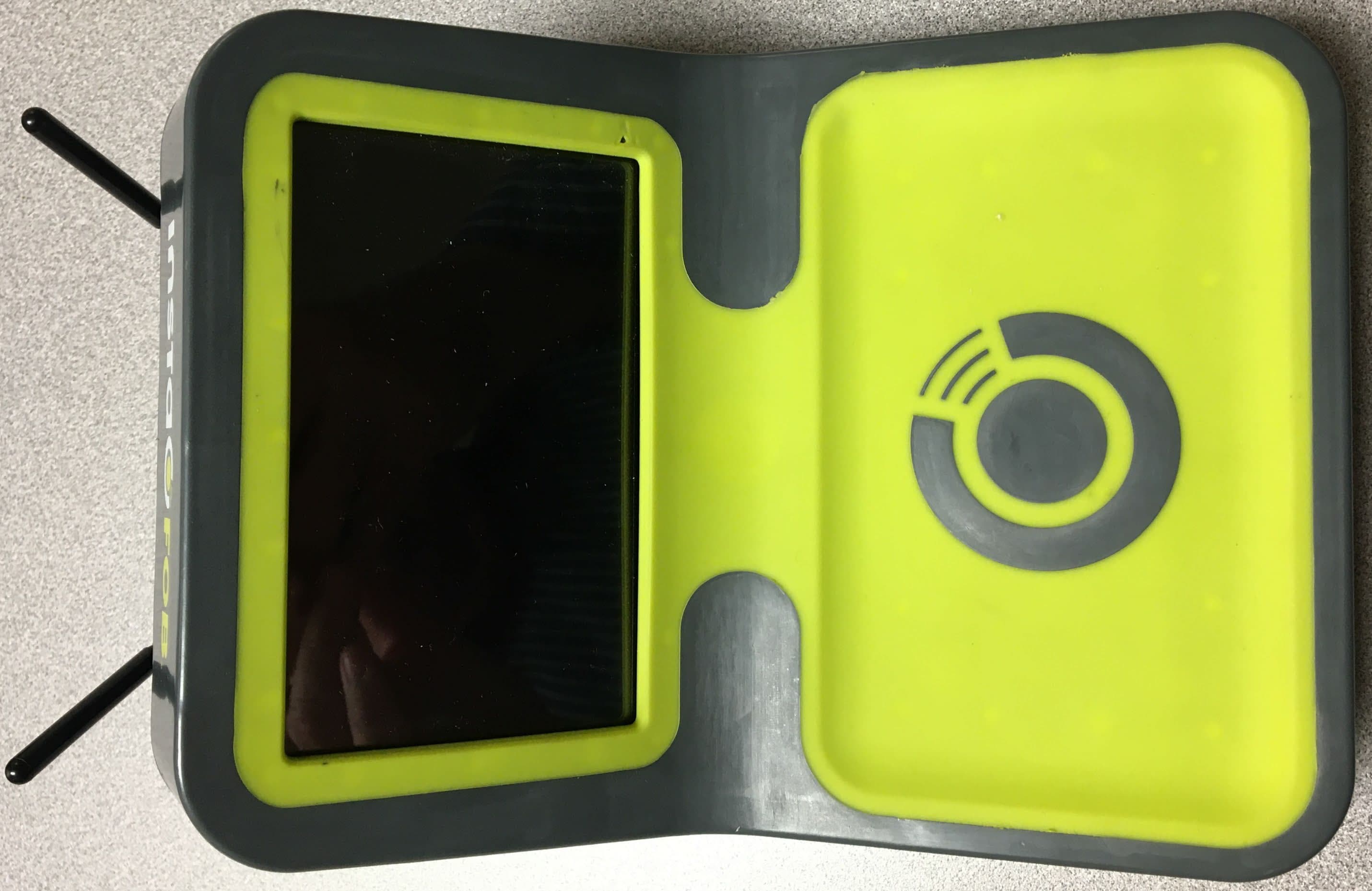
Click to zoom
Application Details
- Equipment Class
- DCD - Part 15 Low Power Transmitter Below 1705 kHz
- Date of Grant
- Mar 09, 2021
- Application Purpose
- Original Equipment
- Date of Application
- Mar 09, 2021
- Equipment Note
- instaFOB
- Frequency Range
- 0.12500000 - 0.12500000
- Company
- The Hillman Group, Inc.
- Country
- United States
Documents & Files
Document Text
Text extracted from the exhibit documents filed with the FCC. Open a document above to read the original.
Users Manual
Page | 1 InstaFob ® Standalone Manual Hillman Group Inc. Company Last Updated 3/01/2021 Version 04 Page | 2 General Grounding Safety Grounding Safety Instruction In the event of a malfunction or breakdown, grounding provides a path of least resistance for electric current to reduce the risk of electric shock. This tool is equipped with an electric cord having an equipment-grounding conductor and a grounding plug. The plug must be plugged into a matching outlet that is properly installed and grounded in accordance with all local codes and ordinances. Do not modify the plug provided – if it will not fit the outlet, have the proper outlet installed by a qualified electrician. Improper connection of the equipment-grounding conductor can result in a risk of electric shock. The conductor with insulation having an outer surface that is green with or without yellow stripes is the equipment-grounding conductor. If repair of replacement of the electric cord or plug is necessary, do not connect the equipment grounding conductor to a live terminal. Check with a qualified electrician or service personnel if the grounding instructions are not completely understood, or if in doubt as to whether the tool is properly grounded. Use only 3-wire extension cords that have 3- prong grounding plugs and 3-pole receptacles that accept the tool’s plug. Repair or replace damaged or worn cord immediately. This tool is intended for use on a circuit that has an outlet that looks like the one illustrated in figure 1. The tool has a grounding plug that looks like the plug illustrated in sketch A of figure 1 from UL 987. A temporary adapter, which looks like the adapter illustrated in Sketches B and C, may be used to connect this plug to a 2-pole receptacle as shown in Sketch B if a properly grounded outlet is not available. The temporary adapter should be used only until a properly grounded outlet can be installed by a qualified electrician. The gree0colored rigid ear, lug, and the like, extending from the adapter must be connected to a permanent ground such as a properly grounded outlet box. CAUTION: If (the internal battery must be replaced, or) internal fuses are blown and require replacement, return the equipment to the manufacturer. These components are not intended to be serviced in the field. In the event of a malfunction or breakdown, grounding provides a path of least resistance for electric current to reduce the risk of electric shock. Page | 3 This equipment has been tested and found to comply with the limits for a Class A digital device, pursuant to part 15 of the FCC Rules. These limits are designed to provide reasonable protection against harmful interference when the equipment is operated in a commercial environment. This equipment generates, uses, and can radiate radio frequency energy and, if not installed and used in accordance with the instruction manual, may cause harmful interference to radio communications. Operation of this equipment in a residential area is likely to cause harmful interference in which case the user will be required to correct the interference at his own expense. This equipment complies with FCC radiation exposure limits set forth for an uncontrolled environment. This equipment should be installed and operated within a minimum distance of 20 cm between the radiator and your body. Page | 4 InstaFob Product Copy Capabilities The InstaFob Machine has the capabilities to read, write and upload to the cloud Access Key Fobs with the frequency of 125Khz. These Fobs are typically used for Access points for HOA common areas, GYMS, POOLs, BOAT GATES and Commercial/Business Accesses. The Device contains an easy to use graphical user interface with a smooth and friendly touch screen. The InstaFob Logo is used to identify the perfect placement target to guarantee a quick, easy and affordable Key Fob copy. InstaFob Machine Layout Machine is indented to be used Interior ONLY. Do not use in exterior conditions. Only Use the provided Power Supply, 5V 8A, 40W that comes with the product. Plug the Power Supply into the “Power Plug” on the machine, and then plug into a max 120V wall plug and please follow the GROUNDING SAFETY recommendation provided in this manual. Page | 5 InstaFob Machine Operations FIRST TIME START UP PROCEDURE: 1) Turn the Machine on by flipping the ON/OFF switch on the back of the device 2) Once the Machine has been turned on and Operating System has been fully loaded select “Get Started” 3) Enter the Unlock Code which is the serial number in reverse – machine will unlock and be ready to operate Page | 6 No Touch Operations | New FOB Copy Page | 7 No Touch Operations | New FOB Copy | Continue Page | 8 No Touch Operations | Previously Saved FOB Copy Page | 9 No Touch Operations | Previously Saved FOB Copy | Continue Page | 10 Errors & Troubleshooting Page | 11 Errors & Troubleshooting | Continue Page | 12 Frequently Asked Questions Q | How long does it takes to copy my Key Fob? A | The entire process, including text message validation and copy time is usually no more than 1 minute per copy. Q | Are you associated with any HOAs or building management? A | No, we are not associated with any building/HOA's and our customers information if completely private. Q | Do you copy any credential cards (that's not the customers) or credit cards? A | ABSOLUTELY NOT! InstaFob follows all local laws and does not copy any kind of suspicious credentials like Government/Military Identification cards, student identification cards and anything that clearly does not look like a simple Key Fob access card. Q | I'm concerned about the safety of my apartment complex in relation to this service. A | To copy a Key Fob, it is safer and more secure then copying a physical key. #1 You must HAVE the original Key Fob (first time) for the process to work. #2 If the building management cancels the original Key Fob code, ALL copies will be canceled as well. Q | What should I do if someone makes an unauthorized…
Text truncated - open the document above for the full version.
External Photos
External Photo TOP SIDE External Photo BACK BOTTOM
ID Label/Location Info
SERIAL NO. MODEL NO. Y0001450 ELECTRICAL RATINGS USA / CANADA 5V, 8A, 60Hz SUITABLE FOR INDOOR USE ONLY THIS DEVICE COMPLIES WITH PART 15 OF THE FCC RULES. OPERATION IS SUBJECT TO THE CONDITION THAT THIS DEVICE DOES NOT CAUSE HARMFUL INTERFERENCE THE HILLMAN GROUP, INC. 8990 S. KRENE RD. TEMPE, AZ 85284 USA 1-800-242-9937 PATENTS PENDING MADE IN USA3136-28 FCC ID: 2AYY8THGINSTFB CONTAINS FCC ID:N7NHL7648
Internal Photos
Internal Photo TOP Internal Photo SIDE TOP WITH DISPLAY REMOVED PCBA Photo RASPBERRY PI TOP RASPBERRY PI BOTTOM PCBA Photo RFID TOP PCBA Photo RFID BOTTOM PCBA Photo INTERCONNECT TOP PCBA Photo INTERCONNECT BOTTOM
RF Exposure Info
Certificates and reports shall not be reproduced except in full, without the written permission of H.B Compliance Solutions, LLC. RF Exposure MPE Report For the The Hillman Group Instafob March 9, 2021 Prepared for: The Hillman Group 8990 S. Kyrene Road, Tempe, AZ 85284 Prepared By: H.B. Compliance Solutions 5005 S. Ash Avenue, Suite # A-10 Tempe, Arizona 85282 Reviewed By: Hoosamuddin Bandukwala Cert # ATL-0062-E HBCS RF Exposure Report # EMC_21001 Page 2 of 5 1. Equipment Overview Product Name: Instafob Model(s) Tested: Y0001450 FCC ID: 2AP6HASM0023 Supply Voltage Input: Primary Power: 120VAC Frequency Range: 0.125 MHz No. of Channels: 1 Type(s) of Modulation: Sinewave Range of Operation Power: 972x10 -9 Watts (Radiated) Emission Designator: N/A Channel Spacing(s) None Test Item: Pre-Production Type of Equipment: Fixed Antenna Requirement (§15.203) : Type of Antenna: Integral Loop Gain of Antenna: 0dBi Environmental Test Conditions: Temperature: 15-35⁰C Humidity: 30-60% Barometric Pressure: 860-1060 mbar Modification to the EUT: None HBCS RF Exposure Report # EMC_21001 Page 3 of 5 2. Applicable Standard According to §1.1307 the criteria listed in table 1 shall be used to evaluate the environmental impact of human exposure to radio frequency (RF) radiation as specified in §1.1307(b), except in the case of portable devices which shall be evaluated according to the provisions of §2.1093 of this chapter. Test Limits Evaluated against exposure limits: General Use _X_ or Controlled Use ___ Maximum Permissible Exposure (MPE) f = frequency in MHz* = Plane-wave equivalent power density RF exposure compliance will need to be determined with respect to 1.1307(c) and (d) of the FCC rules. The emissions should be within the limits at 300kHz in the above table. (Use 300kHz limits for 150kHz) HBCS RF Exposure Report # EMC_21001 Page 4 of 5 3. Test Results Equation from page 18 of OET Bulletin 65, Edition 97-01 S = PG/4πR² Where, S = power density (mW/cm2) P = output power at the antenna terminal (mW) G = gain of transmit antenna (numeric) R = distance from transmitting antenna (cm) Maximum peak output power at antenna input terminal = -50 (dBm) Maximum peak output power at antenna input terminal = 972 (nW) Antenna gain (typical) = 0 (dBi) Maximum antenna gain = 1.0 (numeric) Prediction distance = 20 (cm) Prediction frequency = 0.125 (MHz) MPE limit for uncontrolled exposure at prediction frequency = 100 (mW/cm^2) Power density at prediction frequency = 0 (mW/cm^2) To solve for the minimum mounting distance required; R = √ (PG/4πS) R = √ (972x10 -9 x 1.0 / 4π x 0) = 20 cm (Based on continuous transmission) HBCS RF Exposure Report # EMC_21001 Page 5 of 5 Simultaneous Transmission Evaluation Limit The sum of the ratios of the peak or spatially averaged results to the applicable frequency dependent MPE limits must be <1 at all locations where users and bystanders can by exposed. Calculation Mode Cellular Modem Power Density/Limit 125kHZ RFID Power Density/Limit ∑(Power Density/Limit) of Cellular+125kHz RFID Cellular Modem 0.0767 125kHz RFID 0.0 0.0767 The Cellular and 125kHz RFID transmitter, the aggregated (power density/limit) is smaller than 1, and the MPE of 2 collocated transmitters is compliant. Note: FCC ID for the pre-certified Cellular Modem N7NHL7648. END OF TEST REPORT
Test Report
Certificates and reports shall not be reproduced except in full, without the written permission of H.B Compliance Solutions, LLC. Intentional Radiator Test Report For the The Hillman Group InstaFob Tested under The FCC Rules contained in Title 47 of the CFR, Part 15.209 Prepared for: The Hillman Group, Inc. 8990 S. Kyrene Rd. Tempe, AZ 85284 Prepared By: H.B. Compliance Solutions 5005 S. Ash Avenue, Suite # A-10 Tempe, Arizona 85282 Reviewed By: Hoosamuddin Bandukwala Cert # ATL-0062-E Engineering Statement: The measurements shown in this report were made in accordance with the procedure indicated, and the emissions from this equipment were found to be within the limits applicable. I assume full responsibility for the accuracy and completeness of these measurements, and for the qualifications of all persons taking them. It is further stated that upon the basis of the measurement made, the equipment tested is capable of operation in accordance with the requirements of Part 15 of the FCC Rules under normal use and maintenance. All results contained herein relate only to the sample tested. HBCS Report # EMC_21001 Page 2 of 24 Report Status Sheet Revision # Report Date Reason for Revision Ø Feb 24, 2021 Initial Issue HBCS Report # EMC_21001 Page 3 of 24 Table of Contents EXECUTIVE SUMMARY ............................................................................................ 4 1. Testing Summary ........................................................................................ 4 EQUIPMENT CONFIGURATION ................................................................................ 5 1. Overview .................................................................................................... 5 2. Test Facility ................................................................................................. 6 3. Description of Test Sample ......................................................................... 7 4. Equipment Configuration ........................................................................... 7 5. Support Equipment .................................................................................... 7 6. Ports and Cabling Information .................................................................... 7 7. Method of Monitoring EUT Operation ........................................................ 8 8. Mode of Operation ..................................................................................... 8 9. Modifications ............................................................................................. 8 10. Disposition of EUT ...................................................................................... 8 Criteria for Intentional Radiators ............................................................................ 9 1. Radiated Emissions ..................................................................................... 9 Emissions Tests Calculations ...................................................................... 10 2. Conducted Emissions ................................................................................ 13 2. Occupied Bandwidth ................................................................................ 19 5. Radiated Spurious Emissions .................................................................... 21 Test Equipment ..................................................................................................... 23 6. Measurement Uncertainty ............................................................................ 24 HBCS Report # EMC_21001 Page 4 of 24 EXECUTIVE SUMMARY 1. Testing Summary These tests were conducted on a sample of the equipment for the purpose of demonstrating compliance with Part 15.209. All tests were conducted using measurement procedure from ANSI C63.4-2014, American National Standard for Methods of Measurement of Radio-Noise Emissions from Low-Voltage Electrical and Electronic Equipment in the range of 9kHz to 40GHz and ANSI C63.10-2013 Procedures for Compliance Testing of Unlicensed Wireless Devices as appropriate. Test Name Test Method/Standard Result Comments Unintentional Radiated Emissions 15.109 Pass A/C Power Line Conducted Emissions 15.207(a) Pass Occupied Bandwidth 15.215 Pass Radiated Fundamental Emissions 15.209(a) Pass Radiated Spurious Emissions 15.209(a), 15.205, 15.35(C) Pass HBCS Report # EMC_21001 Page 5 of 24 EQUIPMENT CONFIGURATION 1. Overview H.B Compliance Solutions was contracted by The Hillman Group to perform testing on the InstaFob under the purchase order number 620989OO01. This document describes the test setups, test methods, required test equipment, and the test limit criteria used to perform compliance testing of the The Hillman Group, InstaFob. The tests were based on FCC Part 15 Rules. The tests described in this document were formal tests as described with the objective of the testing was to evaluate compliance of the Equipment Under Test (EUT) to the requirements of the aforementioned specifications. The Hillman Group should retain a copy of this document and it should be kept on file for at least five years after the manufacturing of the EUT has been permanently discontinued. The results obtained relate only to the item(s) tested. Product Name: InstaFob Model(s) Tested: Y0001450 FCC ID: 2AYY8THGINSTFB Supply Voltage Input: Primary Power: 120VAC Frequency Range: 125kHz No. of Channels: 1 Type(s) of Modulation: Sinewave Range of Operation Power: 972nW (Radiated) Emission Designator: N/A Channel Spacing(s) None Test Item: Pre-Production Type of Equipment: Fixed Antenna Requirement (§15.203): Type of Antenna: Integral Loop Gain of Antenna: 0dBi Environmental Test Conditions: Temperature: 15-35⁰C Humidity: 30-60% Barometric Pressure: 860-1060 mbar Modification to the EUT: None Evaluated By: Staff at H.B Compliance Solutions Test Date(s): 01/20/2021 till 01/21/2021 Firmware Number - PCBA Version - HBCS Report # EMC_21001 Page 6 of 24 2. Test Faci…
Text truncated - open the document above for the full version.
Test Setup Photos
1 | P a g e Test Setup Photos Hillman – Project 21001 Test Setup Photo # 1 Test Setup Photo # 2 2 | P a g e Test Setup Photo # 3
Contact Information
Applicant
Conrad Cruz Gonzales(Sr. Manager, Manufacturing Engineering)
Test Firm
H.B. Compliance SolutionsHoosamuddin Bandukwala
[email protected]480-684-2969
Technical Specifications
| # | Rule Parts | Frequency Range | Power Output |
|---|---|---|---|
| 1 | 15C | 0.125 MHz - 0.125 MHz | - |