2AYYN-DDDTRK1DDD Tracker+
Plastimold Products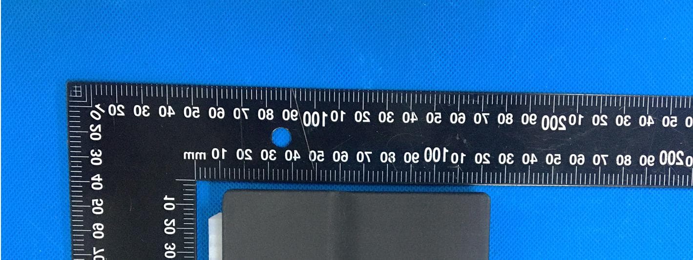
Click to zoom
Application Details
- Equipment Class
- DSR - Part 15 Remote Control/Security Device Transceiver
- Date of Grant
- Apr 14, 2021
- Application Purpose
- Original Equipment
- Date of Application
- Apr 14, 2021
- Equipment Note
- DDD Tracker+
- Frequency Range
- 434.00000000 - 434.00000000
- Company
- Plastimold Products
- Country
- United States
Documents & Files
Document Text
Text extracted from the exhibit documents filed with the FCC. Open a document above to read the original.
Users Manual
INSTALLATION DIAGRAM Page 1 © 2017 Distracted Driving Device, LLC. No party may republish, copy, redistribute, sell or offer for sale to any third party this material or any part of it without express written permission of the authors. If you are making the connections directly at the battery, you MUST use a 3A size inline fuse (as shown). This is a safety precaution in the case of a nicked or pinched wire contacting metal. POTENTIAL INSTALLATION LOCATIONS The Comm Device (PTE-5) should be installed as high in the dash as possible to ensure the best performance and to help prevent tampering. • Above or behind instrument cluster • Above any accessible air vents • Above or behind the radio Note: When mounting the device, the LED’s must be facing up and the device should not be obstructed by metal. WIRING DIAGRAM The Distracted Driving Device (DDD) system is comprised of two separate devices, the DDD Communication Device (PTE-5) and the DDD Handset Dock (DDD-1). Both devices will need to be installed in the vehicle as shown in this document. Starter OBDII Purple (Starter Out) Starter Control Circuit Red (12v Constant) (Cut) Black (Ground) Blue (Starter In) Pink (Ignition) hot while engine cranking Key Fuse Pin16Pin 4 Comm Device (PTE-5)Dock (DDD-1) STEP 1: INSTALL COMM DEVICE GROUND - Attach to a secured bare metal chassis ground location such as to a new or existing threaded fastener, or to a grounded circuit such as Pin 4 of the OBDII connector (as shown). 12v CONSTANT - Any 12v constant source, that is not being monitored by the computer for voltage draw, can be used, like Pin 16 of the OBDII connector (as shown). Use inline fuse if going direct to the battery. DEVICE HARNESS ELECTRICAL CONNECTIONS Page 2 © 2017 Distracted Driving Device, LLC. No party may republish, copy, redistribute, sell or offer for sale to any third party this material or any part of it without express written permission of the authors. IGNITION WIRE- a wire with 12V in “key on” and “crank” positions. STARTER WIRE - the wire with 12V in “crank” position only. Once the starter wire is cut, connect Harness blue wire to key side of starter. Connect Harness purple wire to solenoid side. STARTER WIRE IGNITION WIRE NOTE: For all connections, soldering is recommended. Posi-tap and butt connectors are also acceptable (as shown). NOTE: In late model vehicles, starter and ignition connections should be made under hood, near main fuse relay. If harness wires are not long enough, use 3-in-1 wire or equivalent to extend harness (as shown). NOTE: When making these connections, use grommets if wires must penetrate the firewall and use adequate looming if placing wires in the engine compartment to protect from hot metal surfaces and corrosive liquids. Page 3 © 2017 Distracted Driving Device, LLC. No party may republish, copy, redistribute, sell or offer for sale to any third party this material or any part of it without express written permission of the authors. Install Dock in glove compartment (as shown). Make small hole near Dock location for Ground & 12V Constant wires to pass through. Zip-tie wires underneath glove compartment to secure Dock and prevent removal from mounted location. STEP 2: INSTALL DOCK Dock Ground Wire- Bare metal or a common ground connection is recommended on the passenger side of vehicle (as shown). Dock 12V Constant Wire- Connect Dock 12V Constant to inline fuse (size 3A). Then connect inline fuse to Harness 12V Constant connection as made previously at OBDII connector. Note: Please ensure Dock location and placement will allow unrestricted access by the user to insert their handset into the Dock and easily secure it using the rubber strap. Page 4 © 2017 Distracted Driving Device, LLC. No party may republish, copy, redistribute, sell or offer for sale to any third party this material or any part of it without express written permission of the authors. STEP 3: ACCOUNT SETUP Need Help? Visit: DistractedDrivingDevice.com or Call 1-800-579-9077 Use of the Distracted Driving Device requires the installation of the Distracted Driving Device Application on the user’s handsets (smart phones). The Application can be quickly located by scanning the following QR Code. A) Download the App During the setup of the Application, the user will need to enter the serial numbers of the Comm Device (PTE-5) and the Dock (DDD-1). These serial numbers can be located on the bottom of the devices as well as on the outside of the box as shown below. B) Find the labels DDD-1 DockSN 00000000 PTE-5 EliteSN 00000000 Following the in-App instructions, scan the barcode (or manually enter serial number) for each device. C) Scan the barcodes Follow the instructions in the App to complete the device pairing and account setup. D) Complete Account Setup The Emergency Override is failsafe to be used in the event the required phone has been lost, has a dead battery or is otherwise malfunctioning. When the Emergency Override is used to start the vehicle, a message will be sent to the vehicle owner advising of its use. The DDD system may be bypassed by turning the key to the ignition position and then off 5 times in succession. The vehicle will then be permitted to start without a docked handset. EMERGENCY OVERRIDE:
Users Manual
QUICK START Congratulations on your purchase of the Distracted Driving Device! You have taken an important step to help protect your loved ones from the dangers of driving while distracted. 1. Distracted Driving Device Application In order to use the Distracted Driving Device, all owners/administrators and intended drivers will need to download and install the Distracted Driving Device Application on their mobile device. Visit the page from your mobile device by scanning the QR Code at left or by pointing your browser on your mobile device to https://distracteddrivingdevice.com/app/ During the account setup in the Application, you will be prompted to enter the serial numbers of the two enclosed devices that make up the Distracted Driving Device system. The serial numbers can be located on the underside of each device as well as on labels on the outside of Distracted Driving Device packaging. 2. Installation The Distracted Driving Device requires professional installation to work properly in your vehicle. Please consult a qualified technician to perform the installation of this product. To assist your technician in the installation process, a wiring diagram and instructions can be found on the webpage shown in step 1 above. You should not attempt to install this yourself unless you are professionally trained and have extensive knowledge of automotive wiring and methodology. Need Help? DistractedDrivingDevice.com 1-800-579-9077 [Add WNC part number & Date] Distracted Driving Device Operating Information: Please consult the Distracted Driving Device App, downloaded from Apple App Store or Google Play TM which can be accessed via the QR code on the reverse side of this insert or by going to https://distracteddrivingdevice.com/app/ and selecting the appropriate link for your type of phone. Installation: It is strongly recommended that you have the Distracted Driving Device installed by an accredited professional technician skilled in the installation of automotive electrical devices. See the reverse side of this insert for obtaining installation instructions to provide to your installer. Distracted Driving Device One-Year Limited Warranty Summary: Distracted Driving Device (“DDD”) warrants the included hardware devices and accessories against defects in materials and workmanship under normal use for a period of one year from the date of original purchase (the “Warranty Period”) by Customer. If a hardware defect arises and a valid claim is received within the Warranty Period, DDD at its sole option and discretion will either (1) repair the hardware defect at no charge, using new or refurbished replacement parts, or (2) exchange the product with a product that is new or which has been manufactured from new or serviceable used parts and is at least functionally equivalent to the original product. To obtain service, call 1- 800-579-9077. Subject to the full Limited Warranty terms and conditions at: https://distracteddrivingdevice.com/warranty-policy/ and can also be found in the App Extras section of the Distracted Driver Device Application. FCC Regulations: This device complies with Part 15 of the FCC Rules. Operation is subject to the following two conditions: (1) This device may not cause harmful interference, and (2) this device must accept any interference received, including interference that may cause undesired operation. Changes or modifications not expressly approved by Distracted Driving Device, LLC could void the user‘s authority to operate the equipment. The Comm Device (PTE-5) complies with radio frequency (RF) exposure limits adopted by the Federal Communications Commission for an uncontrolled environment. The Comm Device (PTE-5) should be installed and operated with minimum distance 20 cm between the radiator & your body. This equipment has been tested and found to comply with the limits for a Class B digital device, pursuant to part 15 of the FCC Rules. These limits are designed to provide reasonable protection against harmful interference in a residential installation. This equipment generates uses and can radiate radio frequency energy and, if not installed and used in accordance with the instructions, may cause harmful interference to radio communications. However, there is no © 2017 Distracted Driving Device, LLC guarantee that interference will not occur in a particular installation. If this equipment does cause harmful interference to radio or television reception, which can be determined by turning the equipment off and on, the user is encouraged to try to correct the interference by one or more of the following measures: - R eorient or relocate the receiving antenna. -Increase the separation between the equipment and receiver. - Connect the equipment into an outlet on a circuit different from that to which the receiver is connected. - Consult the dealer or an experienced radio/TV technician for help. IC Regulations: IC Radiation Exposure Statement: The Comm Device (PTE-5) complies with IC RSS-102 radiation exposure limits set forth for an uncontrolled environment. The Comm Device (PTE-5) should be installed and operated with minimum distance 20cm between the radiator & your body. This device and its antenna(s) must not be co-located or operating in conjunction with any other antenna or transmitter. Déclaration d'exposition aux radiations: Cet équipement est conforme aux limites d'exposition aux rayonnements IC établies pour un environnement non contrôlé. Cet équipement doit être installé et utilisé avec un minimum de 20 cm de distance entre la source de rayonnement et votre corps. This Class B digital apparatus complies with Canadian ICES-003. Cet appareil numérique de la classe B est conforme à la norme NMB-003 du Canada. This device complies with Industry Canada’s licence-exempt RSSs. Operation is subject to the following two conditions: 1)This device may not cause interference; and 2)This device must accept any interference, including interference that may cause undesir…
Text truncated - open the document above for the full version.
Cover Letter(s)
Plastimold Products 250 N Congress Ave Delray Beach, FL 33445 Date: 04/01/21 Federal Communications Commission Authorization and Evaluation Division 7435 Oakland Mills Road Columbia, MD 21046 FCC ID: 2AYYN-DDDTRK1 Confidentiality Request To whom it may concern, Pursuant to Sections 0.457 and 0.459 of the Commission’s Rules, we hereby request confidential treatment of the information accompanying this application as outlined below: ☒Block Diagram ☐Tune-Up Information ☒Operational Description ☐Security Information ☒Schematics ☐Software Defined Radio (SDR) Information ☒Parts List The above materials contain trade secrets and proprietary information not customarily released to the public. The public disclosure of these matters might be harmful to the applicant and provide unjustified benefits to its competitors. The applicant understands that pursuant to Rule 0.457, disclosure of this application and all accompanying documentation will not be made before the date of the Grant for this application. Sincerely, Mike Slavik CTO
Cover Letter(s)
Plastimold Products 250 N Congress Ave Delray Beach, FL 33445 Date: 04/01/21 Federal Communications Commission Authorization and Evaluation Division 7435 Oakland Mills Road Columbia, MD 21046 FCC ID: 2AYYN-DDDTRK1 Declaration of Authorization To whom it may concern, I, the undersigned, hereby authorize, Jandy So, of Waltek Testing Group (Shenzhen) Co., Ltd., (WALTEK) to act on our behalf in all manners relating to application for equipment authorization, including signing of all documents relating to these matters. Any and all acts carried out by Jandy So, of Waltek Testing Group (Shenzhen) Co., Ltd., (WALTEK) on our behalf shall have the same effects as acts of our own. I, the undersigned, hereby certify that we are not subject to a denial of federal benefits, that includes FCC benefits, pursuant to Section 5301 of the Anti-Drug Abuse Act of 1988, 21 U.S.C 853(a). This authorization is valid until further written notice from the applicant. Sincerely, Mike Slavik CTO
External Photos
Reference No.: WTX21X02013106W Page 2 of 11 Waltek Testing Group (Shenzhen) Co., Ltd. http://www.semtest.com.cn EXHIBIT 2 - EUT EXTERNAL PHOTOGRAPHS EUT View 1 EUT View 2 Reference No.: WTX21X02013106W Page 3 of 11 Waltek Testing Group (Shenzhen) Co., Ltd. http://www.semtest.com.cn EUT View 3 EUT View 4 Reference No.: WTX21X02013106W Page 4 of 11 Waltek Testing Group (Shenzhen) Co., Ltd. http://www.semtest.com.cn EUT View 5 EUT View 6 Reference No.: WTX21X02013106W Page 5 of 11 Waltek Testing Group (Shenzhen) Co., Ltd. http://www.semtest.com.cn EUT View 7
ID Label/Location Info
Reference No.: WTX21X02013106W Page 1 of 11 Waltek Testing Group (Shenzhen) Co., Ltd. http://www.semtest.com.cn ANNEX EXHIBIT 1 - PRODUCT LABELING Proposed FCC ID Label Format Specifications: The label shall be securely affixed to a permanently attached part of the device, in a location where it is visible or easily accessible to the user, and shall not be readily detachable. The label shall be sufficiently durable to remain fully legible and intact on the device in all normal conditions of use throughout the device’s expected lifetime. Proposed Label Location on EUT FCC ID Label Location
Internal Photos
Reference No.: WTX21X02013106W Page 6 of 11 Waltek Testing Group (Shenzhen) Co., Ltd. http://www.semtest.com.cn EXHIBIT 3 - EUT INTERNAL PHOTOGRAPHS EUT Housing and Board View 1 EUT Housing and Board View 2 Reference No.: WTX21X02013106W Page 7 of 11 Waltek Testing Group (Shenzhen) Co., Ltd. http://www.semtest.com.cn Solder Board-Component View 1 Solder Board-Component View 2 Reference No.: WTX21X02013106W Page 8 of 11 Waltek Testing Group (Shenzhen) Co., Ltd. http://www.semtest.com.cn Solder Board-Component View 3 Antenna View
Test Report
Waltek Testing Group (Shenzhen) Co., Ltd. http://www.semtest.com.cn Page 1 of 23 TEST REPORT Reference No. .................... : WTX21X02013106W FCC ID ................................ : 2AYYN-DDDTRK1 Applicant ........................... : Plastimold Products Address.............................. : 250 N Congress Ave, Delray Beach, FL 33445 Product Name ................... : DDD Tracker+ Test Model. ........................ : DDDTRK1 Standards .......................... : FCC Part 15.231 Date of Receipt sample .... : Feb.24, 2021 Date of Test........................ : Feb.24, 2021 to Mar.09, 2021 Date of Issue ..................... : Mar.09, 2021 Test Result ......................... : Pass Remarks: The results shown in this test report refer only to the sample(s) tested, this test report cannot be reproduced, except in full, without prior written permission of the company. The report would be invalid without specific stamp of test institute and the signatures of compiler and approver. Prepared By: Waltek Testing Group (Shenzhen) Co., Ltd. Address: 1/F., Room 101, Building 1, Hongwei Industrial Park, Liuxian 2nd Road, Block 70 Bao'an District, Shenzhen, Guangdong, China Tel.: +86-755-33663308 Fax.: +86-755-33663309 Tested by: Reviewed By: Approved & Authorized By: Mike Shi / Project Engineer Lion Cai / RF Manager Silin Chen / Manager Reference No.: WTX21X02013106W Page 2 of 23 Waltek Testing Group (Shenzhen) Co., Ltd. http://www.semtest.com.cn TABLE OF CONTENTS 1. GENERAL INFORMATION ...................................................................................................................................4 1.1 PRODUCT DESCRIPTION FOR EQUIPMENT UNDER TEST (EUT) ...............................................................................4 1.2 TEST STANDARDS ...................................................................................................................................................5 1.3 TEST METHODOLOGY .............................................................................................................................................5 1.4 TEST FACILITY .......................................................................................................................................................5 1.5 EUT SETUP AND TEST MODE .................................................................................................................................6 1.6 MEASUREMENT UNCERTAINTY ..............................................................................................................................6 1.7 TEST EQUIPMENT LIST AND DETAILS .....................................................................................................................7 2. SUMMARY OF TEST RESULTS ...........................................................................................................................8 3. ANTENNA REQUIREMENT ..................................................................................................................................9 3.1 STANDARD APPLICABLE .........................................................................................................................................9 3.2 TEST RESULT..........................................................................................................................................................9 4. RADIATED EMISSIONS ....................................................................................................................................... 10 4.1 STANDARD APPLICABLE ....................................................................................................................................... 10 4.2 TEST PROCEDURE ................................................................................................................................................. 11 4.3 CORRECTED AMPLITUDE & MARGIN CALCULATION ............................................................................................ 12 4.4 SUMMARY OF TEST RESULTS/PLOTS .................................................................................................................... 12 5. 20DB BANDWIDTH ............................................................................................................................................... 15 5.1 STANDARD APPLICABLE ....................................................................................................................................... 15 5.1 TEST PROCEDURE ................................................................................................................................................. 15 5.2 SUMMARY OF TEST RESULTS/PLOTS .................................................................................................................... 15 6. TRANSMISSION TIME ......................................................................................................................................... 16 6.1 STANDARD APPLICABLE ....................................................................................................................................... 16 6.2 TEST PROCEDURE ................................................................................................................................................. 16 6.3 SUMMARY OF TEST RESULTS/PLOTS .................................................................................................................... 16 7. DUTY CYCLE ......................................................................................................................................................... 18 7.1 STANDARD APPLICABLE ....................................................................................................................................... 18 7.2 TEST PROCEDURE ................................................................................................................................................. 18 7.3 SUMMARY OF TEST …
Text truncated - open the document above for the full version.
Test Setup Photos
Reference No.: WTX21X02013106W Page 9 of 11 Waltek Testing Group (Shenzhen) Co., Ltd. http://www.semtest.com.cn EXHIBIT 4 - TEST SETUP PHOTOGRAPHS Conducted Emission Test Setup Radiation Emission Test Setup (Below 30MHz) Reference No.: WTX21X02013106W Page 10 of 11 Waltek Testing Group (Shenzhen) Co., Ltd. http://www.semtest.com.cn Radiation Emission Test Setup (30MHz to 1GHz) Radiation Emission Test Setup (1GHz to 18GHz) Reference No.: WTX21X02013106W Page 11 of 11 Waltek Testing Group (Shenzhen) Co., Ltd. http://www.semtest.com.cn Radiation Emission Test Setup (Above 18GHz) ***** END OF REPORT *****
Contact Information
Applicant
Mike Slavik(CTO)
Test Firm
Waltek Testing Group (Shenzhen) Co., Ltd.Jandy So
Technical Specifications
| # | Rule Parts | Frequency Range | Power Output |
|---|---|---|---|
| 1 | 15.231 | 434 MHz - 434 MHz | - |
Other Applications from Plastimold Products

2AYYN-DDDDOCK1
Apr 14, 2021DDD Dock
Equipment Class
DTS - Digital Transmission System