2AYZP-JETSKIBUDDYJETSKI BUDDY
Procom Engineering Inc.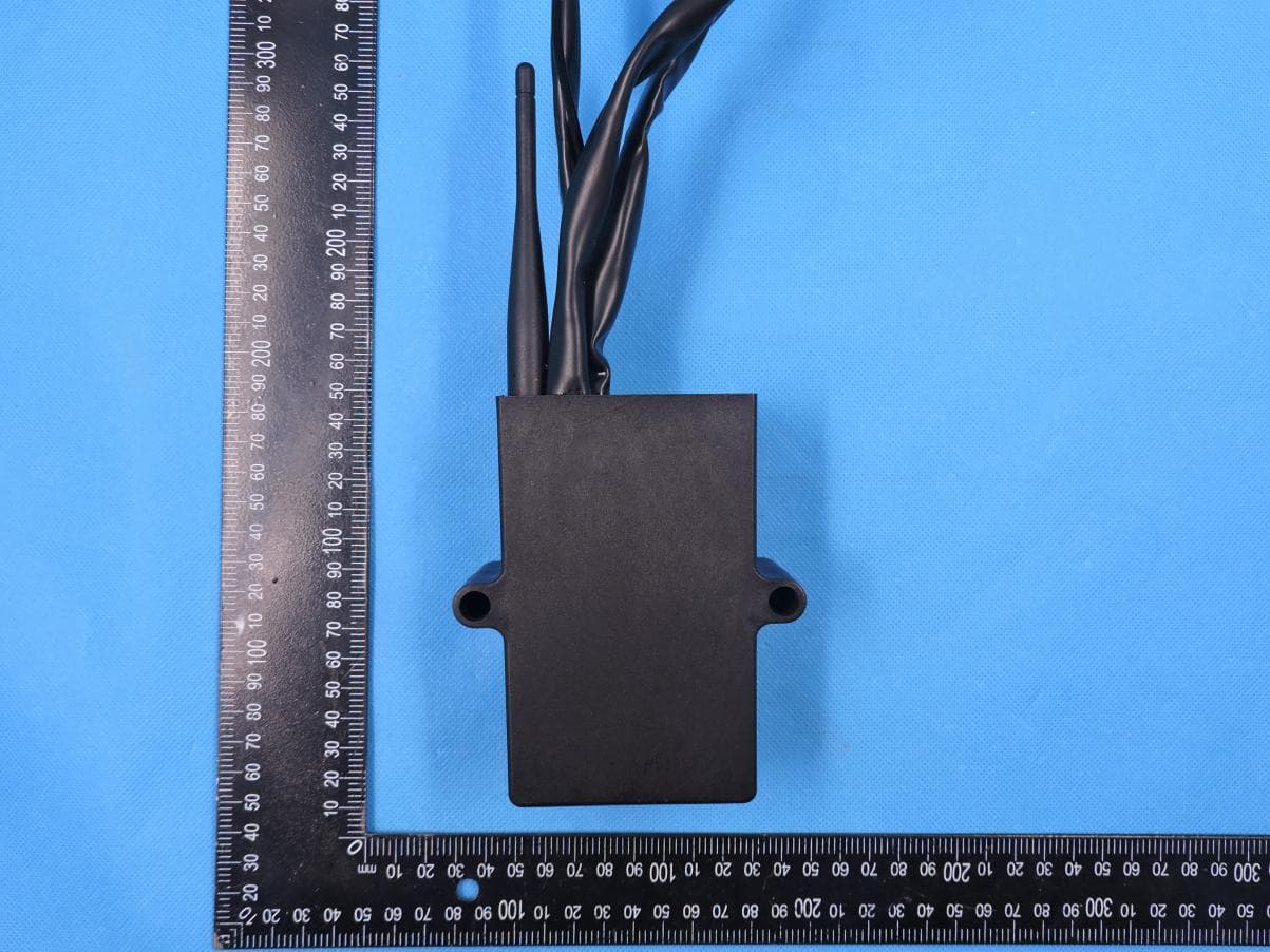
Click to zoom
Application Details
- Equipment Class
- DTS - Digital Transmission System
- Date of Grant
- May 18, 2021
- Application Purpose
- Original Equipment
- Date of Application
- May 18, 2021
- Equipment Note
- JETSKI BUDDY
- Frequency Range
- 2405.00000000 - 2480.00000000
- Company
- Procom Engineering Inc.
- Country
- United States
Documents & Files
Document Text
Text extracted from the exhibit documents filed with the FCC. Open a document above to read the original.
Users Manual
Jetski Buddy User Manual 1. Installation: Disconnect the main connectors on the main wire harness (usually located under the dashboard in the inside chamber or on the sides of the engine room under the seat), and firmly plug the original male connector into Jetski Buddy’s female connector and plug the original female connector into Jetski Buddy’s male connector to make the Jetski Buddy bypass the main wire harness. Next, find a suitable location to mount Jetski Buddy’s main unit with screws or zip ties to ensure that it’s attached firmly. Then, mount the Jetski Buddy’s display to a visible surface with the supplied Dual Sided Tape and mount the GPS antenna to a flat surface inside of the Jetski with the supplied Dual Sided Tape. Note: (1) Before installation, please check your Jetski’s main wire harness connectors to ensure that it matches Jetski Buddy’s main connectors. THE UNIT WILL WORK IF THE CONNECTORS MATCH. You can also watch the installation video on www.JetskiBuddy.com to see how to install Jetski Buddy. (2) The GPS antenna’s symbol side MUST FACE UP when installed. 2. GeoFence Setup: Scan the “START ZONE MARK” tag. All 3 LED lights will flash. Now, you can drive your Jetski to mark your desired zone as a GeoFence. After marking, scan the “FINISH ZONE MARK” tag. If the setup is successful, the 3 lights will stay on for 5 seconds then turn off. Otherwise, the 3 lights will rapidly flash 10 times. Note: (1) Your starting point and ending point don’t have to be in the exact same spot. The device will automatic close it up to make a full loop (refer to below figures). (2) Most failures are due to either the loop being too small or too narrow, or that GPS signal was lost during marking. Please redo it again if the zone set up fails. The previously saved GPS zone will still be in effect if the new set up failed. (3) You can mark a new zone anytime you desire. The new zone will override the old one, as the device can only save the most recent zone. (4) You can mark your zone by driving each Jetski or by using a “Geofence Copier” once and copying the map into multiple Jetskis (Copier sold separately). ! ! ! 3. Operation: 1)When a rental begins, scan the corresponding time tag for the rental duration to start the system. The “Timer” green light on the display will quickly flash 8 times then stay on for the rental duration. During the last 5 minutes of the rental, the green light will slowly flash to alert renters that time is almost up. Once the rental time has run out, the green light will shut off, and the Jetski’s speed will be limited. 2)When the user drives outside of the operating zone, the orange “Out of Zone” light will turn on, and the Jetski’s speed will be limited. Once the user is back in the zone, full speed controls will gradually be restored over a few seconds. 3)Jetski Buddy will communicate with other Jetski Buddy equipped Jetskis over an area of about 80-100 meters and will constantly monitor for Jetski intersections to prevent high speed collisions. When Jetskis are too close to each other, their speed will be limited until they reach a safe distance apart. The red “Keep Apart” light will turn on during this time to indicate that users need to stay apart. Note: (1) When the Jetski Buddy has a GPS signal, the “GPS” light on the top right of the display will be on. Without a GPS signal, the timer function will still work, but zone monitoring and high speed collision prevention functions will not work. (2) You can scan the “KEEP APART OFF”/ “KEEP APART Distance”, “ZONE OFF”/ “ZONE ON”, and “TIMER OFF”/ “TIMER Duration” tags to Disable/Enable each individual function as desired. The according LED light will quickly flash 8 times to indicate a successful scan. The factory default for these 3 functions is OFF. (3) The cut off speed is set by an adjustable dial limiter located on the top of the main device unit. There are 5 levels of limited speed that can be selected from the selector switch on the Jetski Buddy unit itself. The factory default is set to “3”, with “1” being the lowest cut off speed and “5” the fastest cut off speed. FCC Caution. § 15.19 Labeling requirements. This device complies with part 15 of the FCC Rules. Operation is subject to the following two conditions: (1) This device may not cause harmful interference, and (2) this device must accept any interference received, including interference that may cause undesired operation. § 15.21 Changes or modification warning. Any Changes or modifications not expressly approved by the party responsible for compliance could void the user's authority to operate the equipment. § 15.105 Information to the user. Note: This equipment has been tested and found to comply with the limits for a Class B digital device, pursuant to part 15 of the FCC Rules. These limits are designed to provide reasonable protection against harmful interference in a residential installation. This equipment generates uses and can radiate radio frequency energy and, if not installed and used in accordance with the instructions, may cause harmful interference to radio communications. However, there is no guarantee that interference will not occur in a particular installation. If this equipment does cause harmful interference to radio or television reception, which can be determined by turning the equipment off and on, the user is encouraged to try to correct the interference by one or more of the following measures: -Reorient or relocate the receiving antenna. -Increase the separation between the equipment and receiver. -Connect the equipment into an outlet on a circuit different from that to which the receiver is connected. -Consult the dealer or an experienced radio/TV technician for help. This equipment complies with FCC radiation exposure limits set forth for an uncontrolled environment. This equipment should be installed and operated with minimum distance 20cm between the radiator & your body.
Cover Letter(s)
Procom Engineering Inc. Agent Authorization Company: Procom Engineering Inc. Address: 21 Brookline, Aliso Viejo, CA 92656 Product Name: JETSKI BUDDY Model Number(s): JB-Y/S Product Description: Zigbee functional product We authorize MiCOM Labs Inc., 575 Boulder Court, Pleasanton, California 94566, USA, to act on our behalf on all matters concerning the certification of above named equipment. We declare that MiCOM Labs Inc. is allowed to forward all information related to the approval and certification of equipment to the regulatory agencies as required and to discuss any issues concerning the approval application. Any and all acts carried out by MiCOM Labs on our behalf shall have the same effect as acts of our own. Signature: Date: 2021/5/12 Name: Jiankuai Li Title: Manager Company: Shenzhen STS Test Services Co., Ltd.
Cover Letter(s)
2020.05.06 Federal Communications Commission Authorization & Evaluation Division 7345 Oakland Mills Road Columbia, Maryland 21046 RE: LETTER OF AGENT AUTHORIZATION To Whom It May Concern: We, the undersigned, hereby authorize SHENZHEN STS TEST SERVICES CO.,LTD./ A 1/F, Building B, Zhuoke Science Park, No.190 Chongqing Road, HepingShequ, Fuyong Sub-District,Bao’an District, Shenzhen, Guang Dong, China/Jiankuai Li(Name of Agent company name and address, Name of Agent) to act on our behalf in all matters relating to application for equipment authorization, including the signing of all documents relating to these matters. Name: Jiankuai Li Title: PM E-mail:[email protected] This appointment is valid until further until December 31, 2021 Sincerely, Name: Wesley Zhou Title: Manager E-mail: [email protected] Company: Procom Engineering Inc.
Cover Letter(s)
Procom Engineering Inc. Office of Engineering Technology Federal Communications Commission 7435 Oakland Mills Road Columbia, MD 21046 USA Date: 2020/05/12 Subject; Request for Confidentiality FCC ID: 2AYZP-JETSKIBUDDY To Whom It May Concern, Pursuant to the provisions of the Commission’s rules Title 47 Sections §0.457 and §0.459, we are requesting the Commission to withhold the following attachment(s) as confidential documents from public disclosure indefinitely. These documents contain detailed system and equipment descriptions and are considered as proprietary information in operation of the equipment. The public disclosure of these documents might be harmful to our company and would give competitors an unfair advantage in the market. Schematic Diagram Block Diagram Parts List Operational Description Tune-up Procedure In additional to above mentioned documents, in order to comply with the marketing regulations in Title 47 CFR §2.803 and the importation rules in Title 47 CFR §2.1204, while ensuring that business sensitive information remains confidential until the actual marketing of newly authorized devices, we request Short Term Confidentiality of the following attachment(s); External Photos Test Setup Photos Internal Photos User Manual For 45 days, pursuant to Public Notice DA 04-1705. OR For 180 days pursuant to KDB 726920 D01. It is our understanding that all measurement test reports, FCC ID label format and correspondence during the certification review process cannot be granted as confidential documents and this information will be available for public review once the grant of equipment authorization is issued. Sincerely, Signature: Name: Jiankuai Li Title: PM
External Photos
Page 1 of 5 Report No.: STS2104084 APPENDIX-PHOTOGRAPHS OF EUT CONSTRUCTIONAL DETAILS Model: JETSKI BUDDY Photo 1 Photo 2 Photo 3 GPS Antenna Zigbee Antenna Page 2 of 5 Report No.: STS2104084 Photo 4 Page 3 of 5 Report No.: STS2104084 Photo 5 Photo 6 Page 4 of 5 Report No.: STS2104084 Photo 7 Photo 8 Page 5 of 5 Report No.: STS2104084 Photo 9
ID Label/Location Info
FCC Label Product Name: JETSKI BUDDY Model name: JB-Y/S FCC ID: 2AYZP-JETSKIBUDDY This device complies with part 15 of the FCC Rules. Operation is subject to the following two conditions: (1) This device may not cause harmful interference, and (2) this device must accept any interference received, including interference that may cause undesired operation.
Internal Photos
Page 1 of 8 Report No.: STS2104084 APPENDIX-PHOTOGRAPHS OF EUT CONSTRUCTIONAL DETAILS Model: JETSKI BUDDY Photo 1 Photo 2 Photo 3 Page 2 of 8 Report No.: STS2104084 Photo 4 Page 3 of 8 Report No.: STS2104084 Photo 5 Photo 6 Page 4 of 8 Report No.: STS2104084 Photo 7 Photo 8 Page 5 of 8 Report No.: STS2104084 Photo 9 Photo 10 Page 6 of 8 Report No.: STS2104084 Photo 11 Photo 12 Photo 13 Page 7 of 8 Report No.: STS2104084 Photo 14 Page 8 of 8 Report No.: STS2104084 Photo 15 Photo 16
RF Exposure Info
RF Exposure Report FCC ID: 2AYZP-JETSKIBUDDY RF Exposure Measurement The limit for Maximum Permissible Exposure (MPE) specified in FCC 1.1310 is followed. The gain of the antennas used in the product is extracted from the Antenna data sheets provided and also the maximum total power input to the antenna is measured. Through the Friis transmission formula and the maximum gain of the antenna, we can calculate the distance, away from the product, where the limit of MPE is reached. Although the Friis Transmission formula is far field assumption, the calculated result of that is an over-prediction for near field power density. It is taken as worst case to specify the safety range. RF Exposure Limit According to FCC 1.1310: The criteria listed in the following table shall be used to evaluate the environmental impact of the human exposure to radio-frequency (RF) radiation as specified in 1.1307 (b) Limits for Maximum Permissible Exposure (MPE) F= Frequency in MHz Frequency Range (MHz) Electric Field Strength (V/m) Magnetic Field Strength (A/m) Power Density (mW/cm²) Limits for Occupational / controlled Exposures 300 - 1500 -- -- F/300 1500 – 100000 -- -- 5.0 Limits for General population / Uncontrolled Exposure 300 - 1500 -- -- F/1500 1500 – 100000 -- -- 1.0 Friss Formula Friss Transmission Formula: Pd = (Pout * G) / (4*pi*r²) 150.50*3.98/4/3.1416/400 Where Pd = power density in mW/cm² Pout = output power to antenna in mW G = gain of antenna in linear scale Pi = 3.1416 R = Distance between observation point and the center of radiator in cm If we know the maximum gain of the antenna and the total output power to the antenna, through calculation, we will know MPE value at distance 20cm. EUT Operation condition EUT was enabled to transmit and receive at lowest, middle and highest channels. Classification The antenna of this product, under normal use condition, is at least 20cm away from the body of the user. Warning statement to the user for keeping at least 20cm or more separation distance from the antenna should be included in the User manual. So, this device is classified as Mobile device. Zigbee Mode 2405-2480MHz Detector PEAK O-QPSK 21±1dBm ANT Gain (G) Antenna gain : 6dBi (gain of antenna in linear scale=3.98) Protocol ANT Gain(gain of antenna in linear scale) Channel Frequency (MHz) Output Power to Antenna (dBm) Output Power to Antenna (mW) Power Density (mW/cm 2 ) Limit (mW/cm 2 ) O-QPSK 3.98 2405 22 158.50 0.1255224 1 According to the maximum gain of the antenna and the total output power to the antenna, through calculation, we will know max MPE value 0.1255224 at distance 20cm. This is less than the limit 1.So Compliance the RF exposure requirement.
Test Report
Any reproduction of this document must be done in full. No single part of this document may be reproduced without permission from STS, all test data presented in this report is only applicable to presented test sample. Shenzhen STS Test Services Co., Ltd. A 1/F, Building B, Zhuoke Science Park, No.190 Chongqing Road, HepingShequ, Fuyong Sub-District, Bao’an District, Shenzhen, Guang Dong, China TEL: +86-755 3688 6288 FAX: +86-755 3688 6277 E-mail:[email protected] RADIO TEST REPORT Report No.:STS2104084W01 Issued for Procom Engineering Inc. 21 Brookline, Aliso Viejo, CA 92656 Product Name: JETSKI BUDDY Brand Name: Procom Model Name: JB-Y/S Series Model: N/A FCC ID: 2AYZP-JETSKIBUDDY Test Standard: FCC Part 15.247 S T L A B S Page 2 of 43 Report No.: STS2104084W01 TEST RESULT CERTIFICATION Applicant’s Name ................. : Procom Engineering Inc. Address ................................. : 21 Brookline, Aliso Viejo, CA 92656 Manufacturer's Name .......... : Xi'an Procom Engineering Ltd. Address ................................. : No. 69, JinYe Road, Xi'an ShaanXi, China Product Description Product Name ....................... : JETSKI BUDDY Brand Name ........................ : Procom Model Name .......................... : JB-Y/S Series Model ......................... : N/A Test Standards ..................... : FCC Part15.247 Test Procedure ...................... : ANSI C63.10-2013 This device described above has been tested by STS, the test results show that the equipment under test (EUT) is in compliance with the FCC requirements. And it is applicable only to the tested sample identified in the report. This report shall not be reproduced except in full, without the written approval of STS, this document may be altered or revised by STS, personal only, and shall be noted in the revision of the document. Date of Test ........................................... : Date of receipt of test item ..................... : 19 Apr. 2021 Date (s) of performance of tests ............. : 19 Apr. 2021 ~ 08 May 2021 Date of Issue .......................................... : 08 May 2021 Test Result.............................................. : Pass Testing Engineer : (Chris Chen) Technical Manager : (Sean she) Authorized Signatory : (Vita Li) Page 3 of 43 Report No.: STS2104084W01 Table of Contents 1. SUMMARY OF TEST RESULTS 6 1.1 TEST FACTORY 7 1.2 MEASUREMENT UNCERTAINTY 7 2. GENERAL INFORMATION 8 2.1 GENERAL DESCRIPTION OF THE EUT 8 2.2 DESCRIPTION OF THE TEST MODES 10 2.3 TEST SOFTWARE AND POWER LEVEL 10 2.4 BLOCK DIAGRAM SHOWING THE CONFIGURATION OF SYSTEM TESTED 10 2.5 DESCRIPTION OF NECESSARY ACCESSORIES AND SUPPORT UNITS 11 2.6 EQUIPMENTS LIST 12 3. EMC EMISSION TEST 13 3.1 CONDUCTED EMISSION MEASUREMENT 13 3.2 TEST PROCEDURE 14 3.3 TEST SETUP 14 3.4 EUT OPERATING CONDITIONS 14 3.5 TEST RESULTS 14 4. RADIATED EMISSION MEASUREMENT 15 4.1 RADIATED EMISSION LIMITS 15 4.2 TEST PROCEDURE 17 4.3 TEST SETUP 18 4.4 EUT OPERATING CONDITIONS 18 4.5 FIELD STRENGTH CALCULATION 19 4.6 TEST RESULTS 20 5. CONDUCTED SPURIOUS & BAND EDGE EMISSION 27 5.1 LIMIT 27 5.2 TEST PROCEDURE 27 5.3 TEST SETUP 27 5.4 EUT OPERATION CONDITIONS 27 5.5 TEST RESULTS 28 6. POWER SPECTRAL DENSITY TEST 32 6.1 LIMIT 32 6.2 TEST PROCEDURE 32 6.3 TEST SETUP 32 Page 4 of 43 Report No.: STS2104084W01 Table of Contents 6.4 EUT OPERATION CONDITIONS 32 6.5 TEST RESULTS 33 7. BANDWIDTH TEST 35 7.1 LIMIT 35 7.2 TEST PROCEDURE 35 7.3 TEST SETUP 35 7.4 EUT OPERATION CONDITIONS 35 7.5 TEST RESULTS 36 8. PEAK OUTPUT POWER TEST 38 8.1 LIMIT 38 8.2 TEST PROCEDURE 38 8.3 TEST SETUP 39 8.4 EUT OPERATION CONDITIONS 39 8.5 TEST RESULTS 40 9. ANTENNA REQUIREMENT 42 9.1 STANDARD REQUIREMENT 42 9.2 EUT ANTENNA 42 10. EUT TEST PHOTO 43 Page 5 of 43 Report No.: STS2104084W01 Revision History Rev. Issue Date Report NO. Effect Page Contents 00 08 May 2021 STS2104084W01 ALL Initial Issue Page 6 of 43 Report No.: STS2104084W01 1. SUMMARY OF TEST RESULTS Test procedures according to the technical standards: KDB 558074 D01 15.247 Meas Guidance v05r02. FCC Part 15.247,Subpart C Standard Section Test Item Judgment Remark 15.207 Conducted Emission N/A -- 15.247 (a)(2) 6dB Bandwidth PASS -- 15.247 (b)(3) Output Power PASS -- 15.209 Radiated Spurious Emission PASS -- 15.247 (d) Conducted Spurious & Band Edge Emission PASS -- 15.247 (e) Power Spectral Density PASS -- 15.205 Restricted bands of operation PASS -- Part 15.247(d)/ Part 15.209(a) Band Edge Emission PASS -- 15.203 Antenna Requirement PASS -- NOTE: (1) ‘N/A’ denotes test is not applicable in this Test Report. (2) All tests are according to ANSI C63.10-2013. Page 7 of 43 Report No.: STS2104084W01 1.1 TEST FACTORY SHENZHEN STS TEST SERVICES CO., LTD Add. : A 1/F, Building B, Zhuoke Science Park, No.190 Chongqing Road, HepingShequ, Fuyong Sub-District, Bao’an District, Shenzhen, Guang Dong, China FCC test Firm Registration Number: 625569 IC test Firm Registration Number: 12108A A2LA Certificate No.: 4338.01 1.2 MEASUREMENT UNCERTAINTY The reported uncertainty of measurement y ± U, where expended uncertainty U is based on a standard uncertainty multiplied by a coverage factor of k=2, providing a level of confidence of approximately 95 %. No. Item Uncertainty 1 RF output power, conducted ±0.68dB 2 Unwanted Emissions, conducted ±2.988dB 3 All emissions, radiated 9K-30MHz ±2.84dB 4 All emissions, radiated 30M-1GHz ±4.39dB 5 All emissions, radiated 1G-6GHz ±5.10dB 6 All emissions, radiated>6G ±5.48dB 7 Conducted Emission (9KHz-150KHz) ±2.79dB 8 Conducted Emission (150KHz-30MHz) ±2.80dB Page 8 of 43 Report No.: STS2104084W01 2. GENERAL INFORMATION 2.1 GENERAL DESCRIPTION OF THE EUT Product Name JETSKI BUDDY Trade Name Procom Model Name JB-Y/S Series Model N/A Model Difference N/A Product Description The EUT is a JETSKI BUDDY Operation Frequency: 2405-2480MHz Modulation Type: O-QPSK Number Of Channel: Please refer to the Note 2. Antenna Designation: Please refer to the Note 3. Antenna Gain (dBi) 6 dBi Channel List …
Text truncated - open the document above for the full version.
Test Setup Photos
Page 1 of 1 FCC ID: 2AYZP-JETSKIBUDDY DTS Setup photo Model name: JB-Y/S DTS radiation L DTS radiation H
Contact Information
Applicant
Wesley Zhou
Technical Contact
Test Firm
SHENZHEN STS TEST SERVICES CO.,LTD.Bovey Yang
[email protected]+86 755-36886288
Technical Specifications
| # | Rule Parts | Frequency Range | Power Output |
|---|---|---|---|
| 1 | 15C | 2.40 GHz - 2.48 GHz | 133.00 mW |