2AZ2T-GXCAP2Integrated Bluetooth Smart Cap
IMPACX.IO LTD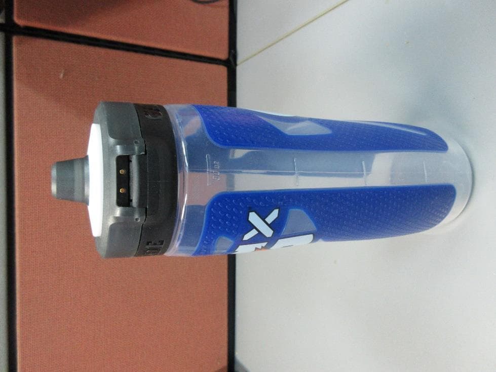
Click to zoom
Application Details
- Equipment Class
- DTS - Digital Transmission System
- Date of Grant
- Feb 07, 2023
- Application Purpose
- Original Equipment
- Date of Application
- Feb 07, 2023
- Equipment Note
- Integrated Bluetooth Smart Cap
- Frequency Range
- 2402.00000000 - 2480.00000000
- Company
- IMPACX.IO LTD
- Country
- Israel
Documents & Files
Document Text
Text extracted from the exhibit documents filed with the FCC. Open a document above to read the original.
Users Manual
Gx Smart Cap Integrated Bluetooth Smart Cap Technical specification IMPACX Gx Smart Cap Technical specification COMMERCIAL impacX Prof. Haim Pekeris St 3, Rehovot, 7670503, Israel www.impacx.io | [email protected] Page 2 of 11 Doc. Ver Date Modified by Changes 1.0 20 Sep 2022 Alexander First draft 2.0 29 Jan 2023 Alexander General updates Gx Smart Cap Technical specification COMMERCIAL impacX Prof. Haim Pekeris St 3, Rehovot, 7670503, Israel www.impacx.io | [email protected] Page 3 of 11 1 Table of contents 1 TABLE OF CONTENTS ....................................................... 3 2 SCOPE 4 2.1 ABSTRACT ................................................................................... 4 2.2 THE PURPOSE OF THE CAP .............................................................. 4 2.3 WHAT THE CAP IS ......................................................................... 4 2.4 ENVIRONMENTAL CONDITIONS ........................................................ 5 3 APPLICABLE DOCUMENTS ............................................... 6 3.1 APPLICABLE DOCUMENTS ............................................................... 6 4 REQUIREMENTS 7 4.1 INTERFACE DEFINITION ................................................................... 7 5 CHARACTERISTICS 8 5.1 VOLUME MEASUREMENT ................................................................ 8 5.2 COMMUNICATION ......................................................................... 9 5.3 BATTERY ................................................................................... 10 6 MECHANICAL STRUCTURE ............................................. 11 6.1 MECHANICAL PARTS .................................................................... 11 6.2 MECHANICAL VIEW ..................................................................... 11 Gx Smart Cap Technical specification COMMERCIAL impacX Prof. Haim Pekeris St 3, Rehovot, 7670503, Israel www.impacx.io | [email protected] Page 4 of 11 2 Scope 2.1 Abstract Drinking enough water each day is crucial for many reasons: to regulate body temperature, keep joints lubricated, prevent infections, deliver nutrients to cells, and keep organs functioning properly. Being well-hydrated also improves sleep quality, cognition, and mood. Smart Cap device on the top of a bottle can help you deeper understand and track the hydration issue relative to your body. 2.2 The purpose of the Cap The Smart Cap is invented to monitor a liquid volume over a long time period, and it would give GX’s customers great insight into how to improve the hydration of a body. 2.3 What the Cap is The Smart Cap is an integrated device that combines mechanical and electronic smart solutions. This is a rechargeable battery-operated device. The battery is powering the device for more than a week. A battery can be charged by a charging adaptor. There is a cable with a universal USB type A connector and a magnetic connector on the Gx Cap side. The Smart Cap measures the volume of a liquid in a bottle upon drinking action. The measured raw data is processed by the cap and sent via Bluetooth wireless communication to a mobile device. A mobile application can show this received and logged data in various combinations. The smart Cap has 21 multicolor LEDs used for various indications and notifications. Gx Smart Cap Technical specification COMMERCIAL impacX Prof. Haim Pekeris St 3, Rehovot, 7670503, Israel www.impacx.io | [email protected] Page 5 of 11 2.4 Environmental conditions Smart caps have electronic components that are protected from environmental conditions both external and internal. External conditions (outside world) include durability, sun protection, temperature, mechanical damage. Internal conditions (inside the bottle) include durability, temperature, mechanical damage and waterproof. Gx Smart Cap Technical specification COMMERCIAL impacX Prof. Haim Pekeris St 3, Rehovot, 7670503, Israel www.impacx.io | [email protected] Page 6 of 11 3 Applicable Documents 3.1 Applicable Documents • Electrical Schematic Diagram • Mechanical drawing • User Manual • Appropriated data sheets Gx Smart Cap Technical specification COMMERCIAL impacX Prof. Haim Pekeris St 3, Rehovot, 7670503, Israel www.impacx.io | [email protected] Page 7 of 11 4 Requirements 4.1 Interface definition • Bluetooth Low Energy (BLE) – for communication • 5Vdc – for charging • Push button Gx Smart Cap Technical specification COMMERCIAL impacX Prof. Haim Pekeris St 3, Rehovot, 7670503, Israel www.impacx.io | [email protected] Page 8 of 11 5 Characteristics 5.1 Volume measurement The product measures a distance from a cap to a surface of a liquid into a bottle and calculates a liquid's volume. Parameter Value Notes Range 0...910 mL Overall Accuracy (typically) ± 50 mL Overall Accuracy (Min/Max) - 70 mL/+60mL Lighting conditions Up to 5 kLux equivalent sunlight Operation method Water level measurement Gx Smart Cap Technical specification COMMERCIAL impacX Prof. Haim Pekeris St 3, Rehovot, 7670503, Israel www.impacx.io | [email protected] Page 9 of 11 5.2 Communication The product can communicate using a Bluetooth wireless communication connection. Bluetooth communication parameters: Parameter Value Notes Communication type Bluetooth low energy (BLE) Bluetooth version V5.2 Transmission power Up to 3dBm Transmission Range up to 30 feet (10 meters) Operation method Advertising (Beacon), Connection Comply with regulations ETSI EN 301 489-1 V2.1.1 (2017-02) ETSI EN 301 489-17 V3.1.1 (2017-02) ETSI EN 300 328 V2.2.2 (2019-07) FCC Part 15 Subpart B and C FCC ID: 2AZ2T-GXCAP2 This device complies with part 15 of the FCC Rules. Operation is subject to the following two conditions: (1) This device may not cause harmful interference, and (2) this device must accept any interference received, including interference that may cause undesired operation. Any changes/modifications to this equipment are not allowed and could void the user’s authority to operate the equipment. Gx Smart Cap Technical specification COMME…
Text truncated - open the document above for the full version.
Attestation Statements
Rev 1/26/2023 Federal Communications Commission Authorization and Evaluation Division 7435 Oakland Mills Road Columbia, MD 21046 USA Date: 01-31-2023 Ref: Attestation Statements Part 2.911(d)(5)(i) Filing FCC ID: 2AZ2T-GXCAP2 ImpacX.io Ltd. (“the applicant”) certifies that the equipment for which authorization is sought is not “covered” equipment prohibited from receiving an equipment authorization pursuant to section 2.903 of the FCC rules. Sincerely, Alexander Brandin Senior Hardware Engineer Rev 1/26/2023 IMPACX.IO LTD 3 Haim Pekeris St., Ruhrberg Science Building, Bell Entrance, 2th floor, Rabin Science Park Rehovot 7670211, Israel Tel: +97283730370; Email: [email protected] Federal Communications Commission Authorization and Evaluation Division 7435 Oakland Mills Road Columbia, MD 21046 USA Date: 01-31-2023 Ref: Attestation Statements Part 2.911(d)(5)(ii) Filing FCC ID: 2AZ2T-GXCAP2 Alexander Brandin (“the applicant”) certifies that, as of the date of the filing of the application, the applicant is not identified on the Covered List as an entity producing “covered” equipment. Sincerely, Alexander Brandin Senior Hardware Engineer
Attestation Statements
Designation of U.S. Agent for Service of Process Explanation: As required by section 2.911(d)(7), the applicant must designate a contact located in the United States for purposes of acting as the applicant’s agent for service of process, regardless of whether the applicant is a domestic or foreign entity. An applicant located in the United States may designate itself as the agent for service of process. In either scenario, the designation of the U.S. agent for service of process should be provided as an attachment to the equipment authorization application. The applicant must provide a written certification, which must: i.Be signed by both the applicant and designated agent for service of process, if the agent is different from the applicant. All signatures must be an actual signature/image or a secured electronic signature such as can be done with Acrobat. ii.Acknowledge the applicant’s consent and the designated agent’s obligation to accept service of process. iii.Provide a physical U.S. address and email for the designated agent. iv.Acknowledge the applicant’s acceptance to maintain an agent for no less than one year after the grantee has terminated all marketing and importation or the conclusion of any Commission-related proceeding involving the equipment. NOTE: The U.S. Agent for Service of Process should not be confused with the authorized agent used for signing the 731 form, other cover letters within the application, and agent who may interface with the TCB. We have provided two letters to follow. The first is intended for when the Designated Agent specified is separate from the Applicant. The second letter is for cases where the applicant is specifying they are both the Applicant and the Agent for Service of Process. Further Clarification provided from the FCC on February 14, 2023 via TCB Council. The Agent for Process of Service: •Should not be a TCB or affiliated with a TCB (e.g. could not be a person who works for a TCB or a company that owns or is owned by the TCB) unless conflict of interest/impartiality has been evaluated. See KDB 986446 Q12. •Agent can be Individual Entity or a Company Entity •Agent Entity must be located in US, US address/phone •Entity acting as Agent must report their FRN of this exists. •Agent letter does not have to be FCC ID specific, can be general Agent for Grantee For devices being marketed or for which marketing has ceased for less than 1 year, if the Agent for Process of Service changes, then for every TC Number the TCB must request the FCC to put application into Audit Mode and Agent Letter needs to be updated (superseded). U.S. Agent Designation for Service of Process (Applicant and U.S. Agent are Separate Parties) TO: Federal Communications Commission Authorization and Evaluation Division 7435 Oakland Mills Road Columbia, MD 21046 USA ATTENTION: FCC Certification – Section 2.911(d)(7) Information Designated U.S. Agent Company Name: Approve-IT, Inc. Contact Name: Nathan Grinager Street Address: 8011 34th Ave South, Suite 342 City/Province/Zip: Bloomington, MN 55425 Telephone No: 651-247-1678 Email: [email protected] FRN #: 0027533835 This letter i s t o confirm that we (“t he Designated U.S . Agent) have accepted the responsibility t o act as the Designated U.S. Agent for Service of Process as required by section 47 CFR 2.911(d)(7) on behalf of the Applicant noted below. U.S. Agent Signature: Date: February 7, 2023 Signed by (Printed Name/Title): Nathan Grinager / Co-President *This letter is valid indefinitely for all applications submitted within the period of 02/08/2023 - 02/07/2024. The Applicant acknowledges that they must maintain an agent for no less than one year after terminating all marketing and importation OR the conclusion of any Commission- related proceeding involving the equipment. The applicant further acknowledges their responsibility to inform the FCC whenever the Designated U.S. Agent information above changes. ImpacX.io Ltd. 2AZ2T-GXCAP2 Alexander Brandin 3 Haim Pekeris St., Ruhrberg Science Building, Bell Entrance, 2th floor, Rabin Science Park Rehovot 7670211, Israel +97283730370 [email protected] Applicant Company name: FCC ID : Contact Name: Street Address: City/Province/Zip: Telephone No: Email: Applicant Signature: Date: February 7, 2023 Signed by (Printed Name/Title): Alexander Brandin, Senior Engineer
Cover Letter(s)
Date: January 11, 2023 To: Federal Communications Commission Office of Engineering and Technology Laboratory Division 7435 Oakland Mills Rd. Columbia MD 21046, USA Subject: Request for Confidentiality Ref: FCC ID number Model FCC ID GX CAP2 2AZ2T-GXCAP2 To whom it may concern: Pursuant to Sections 0.457 and 0.459 of the Commission’s Rules, ImpacX.io Ltd. hereby requests confidential treatment for equipment authorization referenced above. Permanent Confidentiality ImpacX.io Ltd. requests that the Commission withholds the following documents from public viewing indefinitely: • Parts list • Block diagram • Schematics • Operational description The above materials contain trade secrets and proprietary information not customarily released to the public. The public disclosure of these materials may be harmful to the applicant and provide unjustified benefits to its competitors. Short Term Confidentiality In addition to the above-mentioned documents, pursuant to Public Notice DA 04- 1705 of the Commission’s policy, in order to comply with the marketing regulations in 47 CFR §2.803 and the importation rules in 47 CFR §2.1204, while ensuring that business sensitive information remains confidential until the actual marketing of newly authorized devices, ImpacX.io Ltd. requests that the Commission withholds the following documents from public viewing for one hundred eighty days after the date the grant of equipment authorization is issued: • External Photographs • Internal Photographs • Test Setup Photographs • User Manual Sincerely, Alexander Brandin Senior Hardware Engineer
Cover Letter(s)
Date: January 11, 2023 To: Timco Engineering, Inc., an IIA Company 849 NW State Road 45 Newberry, Florida 32669, USA We hereby authorize Mr. Moshe Zohar of I.T.L. Product Testing Ltd., to sign Form 731 on our behalf, for the following FCC certification application: FCC ID: 2AZ2T-GXCAP2 Thank you, Alexander Brandin Senior Hardware Engineer
Cover Letter(s)
Date: January 11, 2023 To Whom It May Concern, We hereby authorize Mr. Moshe Zohar of I.T.L. Product Testing Ltd., to act on our behalf regarding the following FCC certification application: FCC ID: 2AZ2T-GXCAP2 Thank you, Alexander Brandin Senior Hardware Engineer
External Photos
Page 1 of 4 External Photos FCC ID: 2AZ2T-GXCAP2 Page 2 of 4 Page 3 of 4 Page 4 of 4
ID Label/Location Info
Page 1 of 1 FCC ID: 2AZ2T-GXCAP2
Internal Photos
Page 1 of 1 Internal Photos FCC ID: 2AZ2T-GXCAP2
RF Exposure Info
p. 1 of 3 FCC SAR Exclusion Report 1. Product information FCC ID 2AZ2T-GXCAP2 Product Water measurement level sensor with a 2.4 GHz BLE radio Model No. GX CAP2 Power supply Battery, 5 VDC Antenna type PCB Antenna gain 2.11 dBi (max.) Assigned frequency range 2400.0-2483.5 MHz Operating frequency range 2402.0-2480.0 MHz Transmit power (conducted) 1.9 dBm Modulation bandwidth 2 MHz Bit rate 1,2,3 (Mbit/s) SAR exclusion considerations A worst-case test separation distance of 10 mm 2. Evaluation Method and Limit FCC, Part 1, Subpart I, Section 1.1310(e)(1), KDB447498 D01 V06 , Section 4.3.1 and Appendix A ,RSS 102, Issue 5, Section 2.5.1 According to KDB447498 D01 General RF Exposure Guidance v06 Section 4.3.1, the standalone SAR test exclusion considerations are: “Unless specifically required by the published RF exposure KDB procedures, standalone 1-g head or body and 10-g extremity SAR evaluation for general population exposure conditions, by measurement or numerical simulation, is not required when the corresponding SAR Test Exclusion Threshold condition, listed below, is satisfied. The minimum test separation distance is determined by the smallest distance from the antenna and radiating structures or outer surface of the device, according to the host form factor, exposure conditions and platform requirements, to any part of the body or extremity of a user or bystander (see 5) of section 4.1)." p. 2 of 3 SAR exclusion evaluation: 1. Max. (conducted) power: 1.9dBm 2. Antenna gain: 2.1dBi 3. EIRP = max. power + antenna gain = 1.9+2.1 = 4dBm = 2.5mW 4. Minimum distance from human body: 10mm = 0.01m FCC Test Limit For 100 MHz to 6 GHz and test separation distances ≤ 50 mm, the 1-g and 10-g SAR test exclusion thresholds are determined by the following: [(max. power of channel, including tune-up tolerance, mW)/(min. test separation distance, mm)] *·[√f(GHz)] ≤ 3.0 for 1-g SAR and ≤ 7.5 for 10-g extremity SAR. p. 3 of 3 Test Results Frequency FCC calculation FCC limit Verdict (MHz) 2440.0 [(max. power of channel, including tune-up tolerance, mW)/(min. test separation distance, mm)] *·[√f(GHz)]=[2.5/10]*[ √2.4]= 0.38 ≤ 3.0 for 1-g SAR and ≤ 7.5 for 10-g extremity SAR Pass Figure 1 Test Results 3. Conclusion The measurement results comply with the limits per FCC, Part 1, Subpart I, Section 1.1310(e)(1). End of Report
Test Report
GX Smart Cap Antenna Report COMMERCIAL CONFIDENTIAL impacX Bergman 2, Rehovot, 7670503, Israel www.impacx.io | [email protected] Page 1 of 7 The GX Smart Cap uses a specially designed printed antenna. Frequency Range: 2400-2485 MHz Type of antenna: printed, internal Antenna Gain: 2.11dBi Model: VC3_R8 Designed by: Phillip Lindsey, ARSI, LLC Antenna & RF System Integrators [email protected] VC3_R8_optimum1 Figure 1: 3D View VC3_R8 2021-02-14 15:39 Excitation -10.8 -10.6 -10.4 -10.2 -10.0 -9.8 -9.6 2.402.412.422.432.442.452.462.472.482.49 Reflection coefficient [dB] Frequency [GHz] CurrentSource1 Figure 2: Reflection coefficient Magnitude [dB] - VC3_R8_optimum VC3_R8 2021-02-14 15:39 Excitation -10 -5 -3 -2 -1.4 -1 -0.7 -0.5 -0.4 -0.3 -0.2 -0.1 0.1 0.2 0.3 0.4 0.5 0.7 1 1.4 2 3 5 10 0.10.20.30.40.50.7 1 1.4 235 10 CurrentSource1 Figure 3: Impedance - VC3_R8_optimum VC3_R8 2021-02-14 15:39 Power 0.8545 0.8546 0.8547 0.8548 0.8549 0.8550 0.8551 0.8552 0.8553 0.8554 0.8555 2.402.412.422.432.442.452.462.472.482.49 Efficiency Frequency [GHz] Power Figure 4: Efficiency - VC3_R8_optimum VC3_R8 2021-02-14 15:39 VC3_R8_optimum1_1 Figure 5: 3D View VC3_R8 2021-02-14 15:39 Far field -14 -12 -10 -8 -6 -4 -2 0 2 0 30 60 90 120 150 180 210 240 270 300 330 0 config_FarField1 Figure 6: Total Gain [dBi] (Frequency = 2.4425 GHz; Theta = 90 deg) - VC3_R8_optimum VC3_R8 2021-02-14 15:39
Test Report
Test Report Ra258500.02 ImpacX.io Ltd. Page 1 of 44 FCC 15.247 DTS Conducted Ver 1 25.11.2018 Date: 29 January 2023 I.T.L. Product Testing Ltd. FCC Radio Test Report for ImpacX.io Ltd. Equipment under test: Integrated Bluetooth Smart Cap GX CAP FCC ID: 2AZ2T-GXCAP2 Tested by: M. Zohar Approved by: I. Mansky This report must not be reproduced, except in full, without the written permission of I.T.L. Product Testing Ltd. This report relates only to items tested. Test Report Ra258500.02 ImpacX.io Ltd. Page 2 of 44 FCC 15.247 DTS Conducted Ver 1 25.11.2018 This report concerns: Original Grant Equipment type: FCC: (DTS) Digital Transmission System Limits used: 47CFR15 Section 15.247 Measurement procedure used is KDB 558074 D01 v05r01, ANSI C63.10:2013 Prepared by: Applicant: R. Ezrah I.T.L. Product Testing Ltd. 1 Bat Sheva St., Lod 7116002, Israel Email: [email protected] Alexander Brandin ImpacX.io Ltd. 3 Haim Pekeris St., Ruhrberg Science Building Bell Entrance, 2th floor, Rabin Science Park, Rehovot, Israel 7670211 Email: [email protected] Test Report Ra258500.02 ImpacX.io Ltd. Page 3 of 44 FCC 15.247 DTS Conducted Ver 1 25.11.2018 Table of Contents 1. GENERAL INFORMATION --------------------------------------------------------------------------- 5 1.1 Administrative Information ........................................................................... 5 1.2 List of Accreditations ................................................................................... 5 1.3 Product Description ..................................................................................... 6 1.4 Test Methodology ........................................................................................ 6 1.5 Test Facility ................................................................................................. 6 1.6 Measurement Uncertainty ........................................................................... 7 2. SYSTEM TEST CONFIGURATION ----------------------------------------------------------------- 8 2.1 Justification .................................................................................................. 8 2.2 EUT Exercise Software ............................................................................... 8 2.3 Special Accessories .................................................................................... 8 2.4 Equipment Modifications ............................................................................. 8 2.5 Configuration of Tested System .................................................................. 8 3. TEST SETUP PHOTOS ------------------------------------------------------------------------------ 10 4. CONDUCTED EMISSION ON AC MAINS ------------------------------------------------------ 11 4.1 Test Specification ...................................................................................... 11 4.2 Test Procedure .......................................................................................... 11 4.3 Test Limit ................................................................................................... 11 4.4 Test Results............................................................................................... 12 5. 6 DB MINIMUM BANDWIDTH --------------------------------------------------------------------- 18 5.1 Test Specification ...................................................................................... 18 5.2 Test Procedure .......................................................................................... 18 5.3 Test Limit ................................................................................................... 18 5.4 Test Results............................................................................................... 18 5.5 Test Equipment Used; 6dB Bandwidth ..................................................... 20 6. MAXIMUM CONDUCTED OUTPUT POWER -------------------------------------------------- 21 6.1 Test Specification ...................................................................................... 21 6.2 Test Procedure .......................................................................................... 21 6.3 Test Limit ................................................................................................... 21 6.4 Test Results............................................................................................... 21 6.5 Test Equipment Used; Maximum Peak Power Output .............................. 23 7. BAND EDGE SPECTRUM -------------------------------------------------------------------------- 24 7.1 Test Specification ...................................................................................... 24 7.2 Test Procedure .......................................................................................... 24 7.3 Test Limit ................................................................................................... 24 7.4 Test Results............................................................................................... 24 7.5 Test Equipment Used; Band Edge ............................................................ 26 8. TRANSMITTED POWER DENSITY -------------------------------------------------------------- 27 8.1 Test Specification ...................................................................................... 27 8.2 Test Procedure .......................................................................................... 27 8.3 Test Limit ................................................................................................... 27 8.4 Test Results............................................................................................... 27 8.5 Test Equipment Used; Transmitted Power Density .................................. 29 9. OCCUPIED BANDWIDTH -------------------------------------------------------------------------- 30 9.1 Test Specification ......................................................…
Text truncated - open the document above for the full version.
Test Setup Photos
Test Setup Photos FCC ID: 2AZ2T-GXCAP2 Figure 1. Conducted Emission AC Line Test Figure 2. Radiated Emission Test,0.009 30.0MHz Figure 3. Radiated Emission Test, 30.0-200.0MHz Figure 4. Radiated Emission Test, 1.0-18.0GHz
Contact Information
Applicant
Alexander Brandin
Test Firm
ITL PRODUCT TESTING LTDIlan Cohen
Technical Specifications
| # | Rule Parts | Frequency Range | Power Output |
|---|---|---|---|
| 1 | 15C | 2.40 GHz - 2.48 GHz | 1.50 mW |