2AZ3IMP250PROJECTOR
GT Technology Chongqing Limited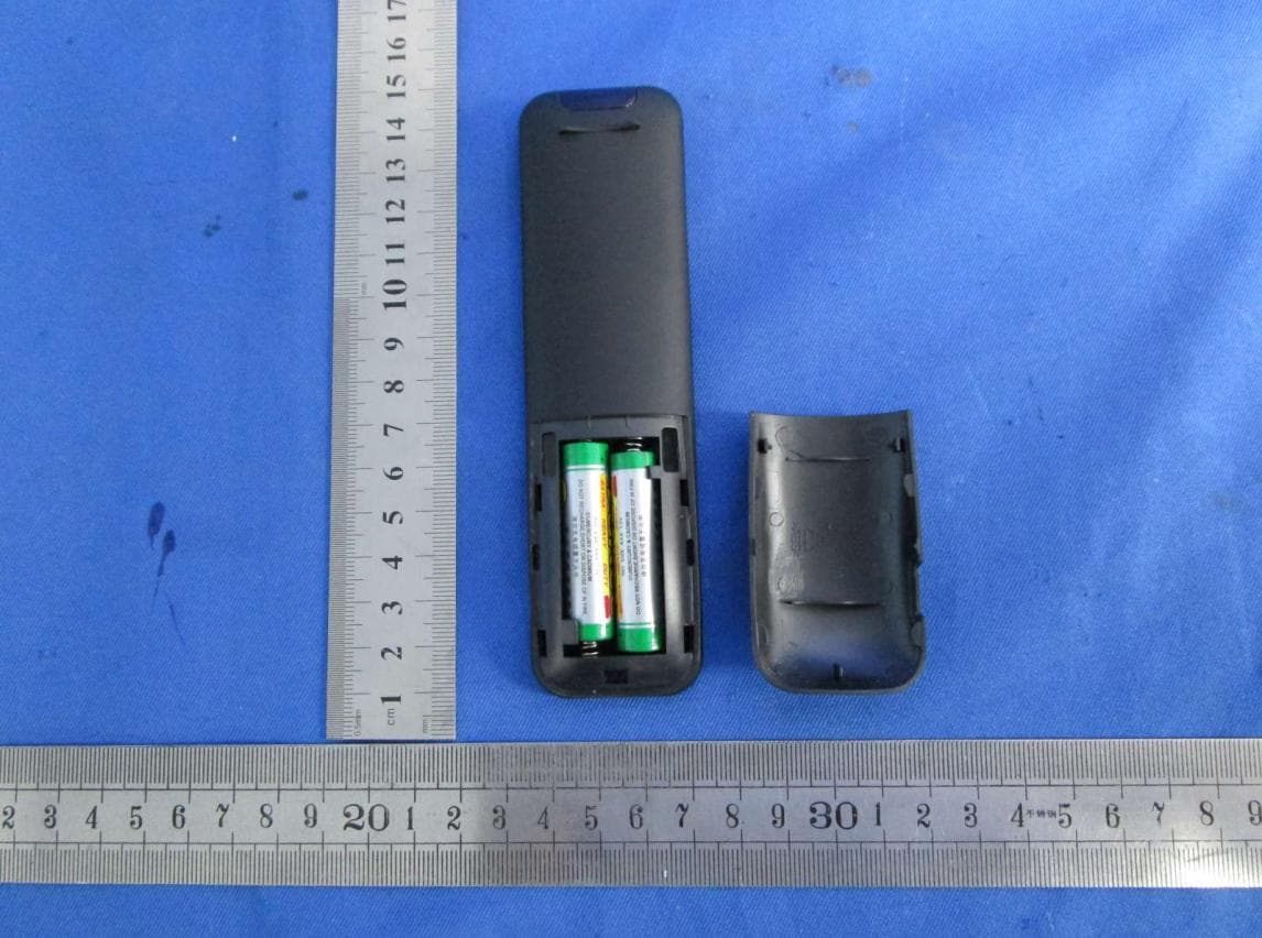
Click to zoom
Application Details
- Equipment Class
- DTS - Digital Transmission System
- Date of Grant
- Jun 28, 2021
- Application Purpose
- Original Equipment
- Date of Application
- Jun 28, 2021
- Equipment Note
- PROJECTOR
- Frequency Range
- 2412.00000000 - 2462.00000000
- Country
- China
Documents & Files
Document Text
Text extracted from the exhibit documents filed with the FCC. Open a document above to read the original.
Cover Letter(s)
Chongqing Shenzhen Taipei DATE 2021/5/14 Equipment Autorisation Division Federal Communications Commission 7435 Oakland Mills Road Columbia, MD 21046 FCC ID: 2AZ3IMP250_ Product Name: PROJECTOR Request for Confidentiality Pursuant to Sections 0.457 and 0.459 of the commissions rules, we hereby request that the following documents be held confidential: (List here the documents for which you are seeking confidentiality – for example ...) Schematics Block diagram Operation description These materials contain trade secrets and proprietary information and are not customarily released to the public. The public disclosure of this information might be harmful to the company and provide unjustified benefits to our competitors. Dated this 2021/5/14 By: Pingan Dai Pingan Dai Signature Printed Title: Certificates engineer On behalf of : GT Technology Chongqing Limited Telephone: 18576493516
Cover Letter(s)
Chongqing Shenzhen Taipei Non-SDR (Software Defined Radio) Cover Letter Date:2021/5/14 Refer to KDB 442812 D01 SDR apps Guide v02r03. The following six questions can be used for determining if a radio can elect to be, or must be an SDR. 1. Can the RF parameters of the device be altered through software? Yes - go to 2. No, not an SDR Yes 2. Can third parties not permitted by the Commission through specific filings modify, configure, or load different software, or make configuration settings to operate the device or host hardware radio frequency parameters (frequency range, modulation type, maximum output power or other radio parameters) in any other way than granted (or expected to be granted)? Yes, must be an SDR. No - go to 3. No 3. Is the device capable of operating in any other in any other way than granted, or will be, granted? Yes, - go to 4. No - go to 5. No 4. Is this a Part 15 client Device as defined in Section 15.202 (as opposed to a master device)? Yes, qualifies as a part 15 client devices - go to 5. No, must be an SDR. 5. Does the manufacturer elect SDR? Yes, elects to be an SDR. No, Not an SDR No Final conclusion: According to the above questions reply, we can confirm this (PROJECTOR), FCC ID: 2AZ3IMP250 must be a Non-SDR. The equipment can only support one exclusive regulation. The hardware devices will be locked to the activated regulatory domain and can’t be modified by any third party through configuration changes or software upgrades. The client only needs to download the software/firmware from official website, and this software/ firmware shall be authentication protocol by the manufacturer. Chongqing Shenzhen Taipei Signature: Pingan Dai Printed Name: Pingan Dai Position: Certificates engineer Company Name: GT Technology Chongqing Limited
Cover Letter(s)
Chongqing Shenzhen Taipei SOFTWARE SECURITY REQUIREMENTS FOR U-NII DEVICES Date: May 14, 2021 ATTN: Pingan Dai FCC Subject: Attestation Letter regarding UNII devices FCC ID: 2AZ3IMP250, Software security questions and answers per KDB 594280 D02 v01r03: General Description 1 Describe how any software/firmware updates for elements than can affect the device’s RF parameters will be obtained, downloaded, validated and installed. For software that is accessed through manufacturer’s website or device’s management system, describe the different levels of security as appropriate. There is no downloadable software provided by the manufacturer that can modify critical radio transmitter parameters. All critical parameters are programmed in Chip memory at the factory and cannot be modified or overridden by third parties. 2 Describe the RF parameters that are modified by any software/firmware without any hardware changes. Are these parameters in some way limited such that any other software/firmware changes will not allow the device to exceed the authorized RF characteristics? There are no RF parameters that can be modified. All RF parameters are programmed in Chip memory at the factory and cannot be modified or overridden by third parties. 3 Describe in detail the authentication protocols that are in place to ensure that the source of the RF-related software/firmware is valid. Describe in detail how the RF-related software is protected against modification. The firmware in the factory has been fixed in to chip, can't change, so there is need for validation. Driver under it operating system provides a digital certificate authentication. 4 Describe in detail any encryption methods used to support the use of legitimate RF-related software/firmware. The firmware in the factory has been fixed in chip, can't be changed, there is no need for validation. Driver is in binary form, it is own closure, no need for verification. 5 For a device that can be configured as a master and client (with active or passive scanning), explain how the device ensures compliance for each mode? In particular if the device acts as master in some band of operation and client in another; how is compliance ensured in each band of operation? Not applicable, this device only supports client without radar detection. The RF parameters has been fixed in the wifi module firmware and cannot be altered, so the user has no way to break the compliance on the device. Third-Party Access Control 1 Explain if any third parties have the capability to operate a U.S.-sold device on any other regulatory domain, frequencies, or in any manner that may allow the device to operate in violation of the device’s authorization if activated in the U.S. Third parties do not have the capability to operate in any manner that is violation of the certification in the U.S Chongqing Shenzhen Taipei 2 Describe, if the device permits third-party software or firmware installation, what mechanisms are provided by the manufacturer to permit integration of such functions while ensuring that the RF parameters of the device cannot be operated outside its authorization for operation in the U.S. In the description include what controls and/or agreements are in place with providers of third-party functionality to ensure the devices’ underlying RF parameters are unchanged and how the manufacturer verifies the functionality. RF parameters are programmed into Chip memory at the factory and cannot be reprogrammed or re-flashed by third parties. 3 For Certified Transmitter modular devices, describe how the module grantee ensures that host manufacturers fully comply with these software security requirements for U-NII devices. If the module is controlled through driver software loaded in the host, describe how the drivers are controlled and managed such that the modular transmitter RF parameters are not modified outside the grant of authorization. There are no RF parameters that can be modified. All RF parameters are programmed in Chip memory at the factory and cannot be modified or overridden by third parties. The module is not controlled by driver software on the host and cannot override critical RF parameters stored in module Chip memory. USER CONFIGURATION GUIDE 1 Describe the user configurations permitted through the UI. If different levels of access are permitted for professional installers, system integrators or end-users, describe the differences. No UI provided. a) What parameters are viewable and configurable by different parties? None b) What parameters are accessible or modifiable by the professional installer or system integrators? None 1) Are the parameters in some way limited, so that the installers will not enter parameters that exceed those authorized? The module micro-code reads the parameters from the module Chip memory. These parameters cannot be modified or overridden by SW drivers. 2) What controls exist that the user cannot operate the device outside its authorization in the U.S.? Default mode is always FCC compliant. Other country modes cannot be activated without receiving three independent country codes from different APs, otherwise remains in FCC default mode (always FCC compliant) c) What parameters are accessible or modifiable by the end-user? None 1) Are the parameters in some way limited, so that the installers will not enter parameters that exceed those authorized? The module micro-code reads the parameters from the module Chip memory. These parameters cannot be modified or overridden by SW drivers. 2) What controls exist so that the user cannot operate the device outside its authorization in the U.S.? Default mode is always FCC compliant. Other country modes cannot be activated without receiving three independent country codes from different APs, otherwise remains in FCC default mode (always FCC compliant) d) Is the country code factory set? Can it be changed in the UI? Default country code is set in the factory and no UI is provided for modification…
Text truncated - open the document above for the full version.
Cover Letter(s)
Chongqing Shenzhen Taipei Attestation Letter Date: May 14, 2019 Federal Communications Commission Authorization and Evaluation Division FCC ID: 2AZ3IMP250 We, GT Technology Chongqing Limited COMPANY, declare that the device does not support channel 12 ~ 13 in 2.4 GHz band and any non-US channels in all the operational mode(s) for the following product. Product: PROJECTOR Model: MP250 FCC ID: 2AZ3IMP250 If you should have any question(s) regarding this declaration, please don’t hesitate to contact us. Thank you! Sincerely, Printed Name: Pingan Dai Position: Certificates engineer Company Name: GT Technology Chongqing Limited COMPANY V1.0
External Photos
AUDIX Technology (Shenzhen) Co., Ltd. Audix Technology (Shenzhen) Co., Ltd. Appendix B Page 1 of 19 Appendix B. Photo of the EUT Figure 1 Appearance Figure 2 Appearance AUDIX Technology (Shenzhen) Co., Ltd. Audix Technology (Shenzhen) Co., Ltd. Appendix B Page 2 of 19 Figure 3 Appearance Figure 4 Remote Controller AUDIX Technology (Shenzhen) Co., Ltd. Audix Technology (Shenzhen) Co., Ltd. Appendix B Page 3 of 19 Figure 5 General Appearance of the EUT Figure 6 General Appearance of the EUT AUDIX Technology (Shenzhen) Co., Ltd. Audix Technology (Shenzhen) Co., Ltd. Appendix B Page 4 of 19 Figure 7 General Appearance of the EUT Figure 8 General Appearance of the EUT AUDIX Technology (Shenzhen) Co., Ltd. Audix Technology (Shenzhen) Co., Ltd. Appendix B Page 5 of 19 Figure 9 General Appearance of the EUT Figure 10 I/O Port of the EUT
ID Label/Location Info
刀模料号设计制作者 类别 材质200g铜版纸贴纸 制法 印色 尺寸 日期 □彩盒 □外箱 □内箱 □说明书 ☑Label □机身LOGO □其他 □模具雕刻 □铜版印刷 □平板印刷 ☑丝网印刷 □POLY □压凸 □压凹 □其他 □单色(特别色) ☑单色(黑色) □三色 □四色 □五色 □其他 □A4 □A5 □A6 □3’’x3’’(76x76mm) □5’’x3’’(126x76mm) □6’’x4’’(152x102mm) ☑其他:直径64.2mm圆,切出25.3mm 李昆昇2021.6.8 料号80-500-20006-100 80-000-00007-000 品名MP250 Label 版本2.0 Label Location
Internal Photos
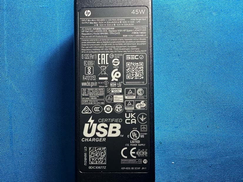
AUDIX Technology (Shenzhen) Co., Ltd. Audix Technology (Shenzhen) Co., Ltd. Appendix B Page 6 of 19 Figure 11 Inside of the EUT Figure 12 Inside of the EUT FPC antenna AUDIX Technology (Shenzhen) Co., Ltd. Audix Technology (Shenzhen) Co., Ltd. Appendix B Page 7 of 19 Figure 13 Inside of the EUT Figure 14 Inside of the EUT AUDIX Technology (Shenzhen) Co., Ltd. Audix Technology (Shenzhen) Co., Ltd. Appendix B Page 8 of 19 Figure 15 Inside of the EUT Figure 16 Inside of the EUT AUDIX Technology (Shenzhen) Co., Ltd. Audix Technology (Shenzhen) Co., Ltd. Appendix B Page 9 of 19 Figure 17 Inside of the EUT Figure 18 Inside of the EUT AUDIX Technology (Shenzhen) Co., Ltd. Audix Technology (Shenzhen) Co., Ltd. Appendix B Page 10 of 19 Figure 19 Inside of the EUT Figure 20 Inside of the EUT AUDIX Technology (Shenzhen) Co., Ltd. Audix Technology (Shenzhen) Co., Ltd. Appendix B Page 11 of 19 Figure 21 Inside of the EUT Figure 22 Inside of the EUT AUDIX Technology (Shenzhen) Co., Ltd. Audix Technology (Shenzhen) Co., Ltd. Appendix B Page 12 of 19 Figure 23 Inside of the EUT Figure 24 Inside of the EUT AUDIX Technology (Shenzhen) Co., Ltd. Audix Technology (Shenzhen) Co., Ltd. Appendix B Page 13 of 19 Figure 25 Inside of the EUT Figure 26 Inside of the EUT AUDIX Technology (Shenzhen) Co., Ltd. Audix Technology (Shenzhen) Co., Ltd. Appendix B Page 14 of 19 Figure 27 Inside of the EUT Figure 28 Fan AUDIX Technology (Shenzhen) Co., Ltd. Audix Technology (Shenzhen) Co., Ltd. Appendix B Page 15 of 19 Figure 29 Fan Figure 30 Frontside of the Main Board AUDIX Technology (Shenzhen) Co., Ltd. Audix Technology (Shenzhen) Co., Ltd. Appendix B Page 16 of 19 Figure 31 Frontside of the Main Board Figure 32 PCB of the EUT AUDIX Technology (Shenzhen) Co., Ltd. Audix Technology (Shenzhen) Co., Ltd. Appendix B Page 17 of 19 Figure 33 PCB of the EUT Figure 34 PCB of the EUT AUDIX Technology (Shenzhen) Co., Ltd. Audix Technology (Shenzhen) Co., Ltd. Appendix B Page 18 of 19 Figure 35 Adapter Figure 36 Adapter AUDIX Technology (Shenzhen) Co., Ltd. Audix Technology (Shenzhen) Co., Ltd. Appendix B Page 19 of 19 Figure 37 Label of the Adapter
RF Exposure Info
Audix Technology (Shenzhen) Co., Ltd. Tel: 0755 26639496 No. 6, Kefeng Road, Science & Technology Park, Fax: 0755 26632877 Nanshan District , Shenzhen, Guangdong, China Maximum Permissive Exposure FCC ID: 2AZ3IMP250 Product Name: PROJECTOR M/N: MP250 1. According to FCC CFR 47 §1.1310, the criteria listed in the following table shall be used to evaluate the environmental impact of human exposure to radio frequency (RF) radiation as specified in 1.1307(b). Table 1 Limits for Maximum Permissible Exposure Frequency Range (MHz) Electric Field Strength (V/m) Magnetic Field Strength (A/m) Power Density (mW/cm 2 ) Average Time (Minutes) (A) Limits for Occupational / Control Exposures (f = frequency) 30-300 61.4 0.163 1.0 6 300-1500 --- --- f/300 6 1500-100,000 --- --- 5.0 6 (B) Limits for General Population / Uncontrolled Exposures (f = frequency) 30-300 27.5 0.073 0.2 30 300-1500 --- --- f/1500 30 1500-100,000 --- --- 1.0 30 2. MPE Calculation GT Technology Chongqing Limited declares that the product described above has been evaluated and found to comply with the RF exposure limits for humans, as specified based on ANSI/FCC recommendation. RF Exposure Calculations: S = (P * G) / (4* π * r^2) or r = √(P * G) / (4 * π * S) Audix Technology (Shenzhen) Co., Ltd. Tel: 0755 26639496 No. 6, Kefeng Road, Science & Technology Park, Fax: 0755 26632877 Nanshan District , Shenzhen, Guangdong, China 2.1. Estimation Result Bluetooth: Mode Frequency (MHz) PK Output power (dBm) Output power (mW) antenna Gain (dBi) antenna Gain (linear) MPE (mW/cm 2 ) GFSK (DSS) 2402 7.841 6.08 -2.31 0.59 0.00071 2441 8.800 7.59 -2.31 0.59 0.00089 2480 9.424 8.76 -2.31 0.59 0.00102 8-DPSK (DSS) 2402 6.747 4.73 -2.31 0.59 0.00055 2441 7.360 5.45 -2.31 0.59 0.00064 2480 7.660 5.83 -2.31 0.59 0.00068 GFSK (DTS) (1Mbps) 2402 4.487 2.81 -2.31 0.59 0.00033 2440 4.950 3.13 -2.31 0.59 0.00037 2480 4.954 3.13 -2.31 0.59 0.00037 GFSK (DTS) (2Mbps) 2402 4.495 2.82 -2.31 0.59 0.00033 2440 4.964 3.14 -2.31 0.59 0.00037 2480 4.948 3.12 -2.31 0.59 0.00037 WiFi 2.4GHz: Mode Frequency (MHz) PK Output power (dBm) Output power (mW) antenna Gain (dBi) antenna Gain (linear) MPE (mW/cm 2 ) 11b (DTS) 2412 16.09 40.64 -2.31 0.59 0.00475 2437 18.80 75.86 -2.31 0.59 0.00887 2462 16.31 42.76 -2.31 0.59 0.00500 11g (DTS) 2412 15.57 36.06 -2.31 0.59 0.00422 2437 15.21 33.19 -2.31 0.59 0.00388 2462 15.75 37.58 -2.31 0.59 0.00439 11n HT20 (DTS) 2412 16.09 40.64 -2.31 0.59 0.00475 2437 15.85 38.46 -2.31 0.59 0.00450 2462 16.46 44.26 -2.31 0.59 0.00518 Audix Technology (Shenzhen) Co., Ltd. Tel: 0755 26639496 No. 6, Kefeng Road, Science & Technology Park, Fax: 0755 26632877 Nanshan District , Shenzhen, Guangdong, China WiFi 5GHz: Mode Frequency (MHz) PK Output power (dBm) Output power (mW) antenna Gain (dBi) antenna Gain (linear) MPE (mW/cm 2 ) 11a (U-NII-1) 5180 12.77 18.92 1.81 1.52 0.00571 5200 12.42 17.46 1.81 1.52 0.00527 5240 11.57 14.35 1.81 1.52 0.00433 11n HT20 (U-NII-1) 5180 12.37 17.26 1.81 1.52 0.00521 5200 11.97 15.74 1.81 1.52 0.00475 5240 11.26 13.37 1.81 1.52 0.00404 11n HT40 (U-NII-1) 5190 8.30 6.76 1.81 1.52 0.00204 5230 7.36 5.45 1.81 1.52 0.00164 11ac VHT20 (U-NII-1) 5180 12.33 17.10 1.81 1.52 0.00516 5200 11.49 14.09 1.81 1.52 0.00426 5240 11.03 12.68 1.81 1.52 0.00383 11ac VHT40 (U-NII-1) 5190 8.28 6.73 1.81 1.52 0.00203 5230 7.37 5.46 1.81 1.52 0.00165 11ac VHT80 (U-NII-1) 5210 7.55 5.69 1.81 1.52 0.00172 Audix Technology (Shenzhen) Co., Ltd. Tel: 0755 26639496 No. 6, Kefeng Road, Science & Technology Park, Fax: 0755 26632877 Nanshan District , Shenzhen, Guangdong, China Mode Frequency (MHz) PK Output power (dBm) Output power (mW) antenna Gain (dBi) antenna Gain (linear) MPE (mW/cm 2 ) 11a (U-NII-3) 5745 10.85 12.16 1.8 1.51 0.00366 5785 11.00 12.59 1.8 1.51 0.00379 5825 10.93 12.39 1.8 1.51 0.00373 11n HT20 (U-NII-3) 5745 10.59 11.46 1.8 1.51 0.00345 5785 10.67 11.67 1.8 1.51 0.00352 5825 10.49 11.19 1.8 1.51 0.00337 11n HT40 (U-NII-3) 5755 6.68 4.66 1.8 1.51 0.00140 5795 6.75 4.73 1.8 1.51 0.00143 11ac VHT20 (U-NII-3) 5745 10.42 11.02 1.8 1.51 0.00332 5785 10.59 11.46 1.8 1.51 0.00345 5825 10.59 11.46 1.8 1.51 0.00345 11ac VHT40 (U-NII-3) 5755 6.44 4.41 1.8 1.51 0.00133 5795 6.88 4.88 1.8 1.51 0.00147 11ac VHT80 (U-NII-3) 5775 6.08 4.06 1.8 1.51 0.00122 Based on safety distance (r) 20cm, the antenna gain (G) is 0.59 Numerical, and the highest power output (P) is 75.86mW, the power density (S) is 0.00887mW/cm 2 . Note: This device only one antenna, it does not support simultaneous.
Test Report
AUDIX Technology (Shenzhen) Co., Ltd. FCC ID: 2AZ3IMP250 Audix Technology (Shenzhen) Co., Ltd. Report No. ACS-F21159 Page 1 of 119 FCC PART 15C TEST REPORT FOR CERTIFICATION On Behalf of GT Technology Chongqing Limited Projector Model No.: MP250 FCC ID: 2AZ3IMP250 Prepared for : GT Technology Chongqing Limited Room 3-1, No.20 Qixin Road Yanjia Street Changshou District, Chongqing, China Prepared By : Audix Technology (Shenzhen) Co., Ltd. No. 6, Kefeng Road, Science & Technology Park, Nanshan District , Shenzhen, Guangdong, China Tel: (0755) 26639496 Report Number : ACS-F21159 Date of Test : May.09~Jun.03, 2021 Date of Report : Jun.25, 2021 AUDIX Technology (Shenzhen) Co., Ltd. FCC ID: 2AZ3IMP250 Audix Technology (Shenzhen) Co., Ltd. Report No. ACS-F21159 Page 2 of 119 TABLE OF CONTENTS Description Page 1. SUMMARY OF STANDARDS AND RESULTS ............................................................. 5 1.1. Description of Standards and Results ..................................................................................... 5 2. GENERAL INFORMATION ............................................................................................. 6 2.1. Description of Equipment Under Test .................................................................................... 6 2.2. Feature of Equipment Under Test ........................................................................................... 7 2.3. Tested Supporting System Details .......................................................................................... 8 2.4. Block diagram of connection between the EUT and simulators ............................................. 8 2.5. Test Information ...................................................................................................................... 9 2.6. Test Facility ........................................................................................................................... 10 2.7. Measurement Uncertainty (95% confidence levels, k=2) ..................................................... 10 3. POWER LINE CONDUCTED EMISSION TEST ........................................................ 11 3.1. Test Equipments .................................................................................................................... 11 3.2. Block Diagram of Test Setup ................................................................................................ 11 3.3. Power Line Conducted Emission Test Limits ....................................................................... 11 3.4. Configuration of EUT on Test .............................................................................................. 12 3.5. Operating Condition of EUT ................................................................................................. 12 3.6. Test Procedure ....................................................................................................................... 12 3.7. Power Line Conducted Emission Test Results ..................................................................... 12 4. RADIATED EMISSION TEST ........................................................................................ 15 4.1. Test Equipment ..................................................................................................................... 15 4.2. Block Diagram of Test Setup ................................................................................................ 16 4.3. Radiated Emission Limit ....................................................................................................... 17 4.4. EUT Configuration on Test ................................................................................................... 17 4.5. Operating Condition of EUT ................................................................................................. 18 4.6. Test Procedure ....................................................................................................................... 18 4.7. Radiated Emission Test Results ............................................................................................ 18 5. CONDUCTED SPURIOUS EMISSIONS ....................................................................... 76 5.1. Test Equipment ..................................................................................................................... 76 5.2. Limit ...................................................................................................................................... 76 5.3. Test Procedure ....................................................................................................................... 76 5.4. Test result .............................................................................................................................. 76 6. BAND EDGE COMPLIANCE TEST .............................................................................. 83 6.1. Test Equipment ..................................................................................................................... 83 6.2. Limit ...................................................................................................................................... 83 6.3. Test Procedure ....................................................................................................................... 83 6.4. Test Results ........................................................................................................................... 83 7. 6dB Bandwidth Test ........................................................................................................ 108 7.1. Test Equipment ................................................................................................................... 108 7.2. Limit .................................................................................................................................... 108 7.3. Test Procedure .......................…
Text truncated - open the document above for the full version.
Test Report
AUDIX Technology (Shenzhen) Co., Ltd. FCC ID:2AZ3IMP250 Audix Technology (Shenzhen) Co., Ltd. Report No. ACS-F21158 Page 1 of 67 FCC PART 15C TEST REPORT FOR CERTIFICATION On Behalf of GT Technology Chongqing Limited Projector Model No.: MP250 FCC ID: 2AZ3IMP250 Prepared for : GT Technology Chongqing Limited Room 3-1, No.20 Qixin Road Yanjia Street Changshou District, Chongqing, China Prepared By : Audix Technology (Shenzhen) Co., Ltd. No. 6, Kefeng Road, Science & Technology Park, Nanshan District , Shenzhen, Guangdong, China Tel: (0755) 26639496 Report Number : ACS-F21158 Date of Test : May.08~24, 2021 Date of Report : Jun.25, 2021 AUDIX Technology (Shenzhen) Co., Ltd. FCC ID:2AZ3IMP250 Audix Technology (Shenzhen) Co., Ltd. Report No. ACS-F21158 Page 2 of 67 TABLE OF CONTENTS Description Page 1. SUMMARY OF STANDARDS AND RESULTS ............................................................. 5 1.1. Description of Standards and Results ..................................................................................... 5 2. GENERAL INFORMATION ............................................................................................. 6 2.1. Description of Equipment Under Test .................................................................................... 6 2.2. Tested Supporting System Details .......................................................................................... 8 2.3. Block Diagram of connection between EUT and simulators .................................................. 8 2.4. Test information ...................................................................................................................... 8 2.5. Test Facility ............................................................................................................................ 8 2.6. Measurement Uncertainty (95% confidence levels, k=2) ....................................................... 9 3. POWER LINE CONDUCTED EMISSION TEST ........................................................ 10 3.1. Test Equipments .................................................................................................................... 10 3.2. Block Diagram of Test Setup ................................................................................................ 10 3.3. Power Line Conducted Emission Test Limits....................................................................... 10 3.4. Configuration of EUT on Test .............................................................................................. 11 3.5. Operating Condition of EUT................................................................................................. 11 3.6. Test Procedure ...................................................................................................................... 11 3.7. Power Line Conducted Emission Test Results ..................................................................... 11 4. RADIATED EMISSION MEASUREMENT .................................................................. 14 4.1. Test Equipment ..................................................................................................................... 14 4.2. Block Diagram of Test Setup ................................................................................................ 15 4.3. Radiated Emission Limit Standard: ...................................................................................... 16 4.4. EUT Configuration on Test .................................................................................................. 16 4.5. Operating Condition of EUT................................................................................................. 16 4.6. Test Procedure ...................................................................................................................... 16 4.7. Radiated Emission Test Results ............................................................................................ 17 5. CONDUCTED SPURIOUS EMISSIONS ....................................................................... 45 5.1. Test Equipment ..................................................................................................................... 45 5.2. Block Diagram of Test Setup ................................................................................................ 45 5.3. Limit ...................................................................................................................................... 45 5.4. Test Procedure ...................................................................................................................... 45 5.5. Test result .............................................................................................................................. 45 6. 6dB BANDWIDTH TEST ................................................................................................ 52 6.1. Test Equipment ..................................................................................................................... 52 6.2. Limit ...................................................................................................................................... 52 6.3. Test Procedure ...................................................................................................................... 52 6.4. Test Results ........................................................................................................................... 52 7. MAXIMUM PEAK OUTPUT POWER TEST ............................................................... 54 7.1. Test Equipment ..................................................................................................................... 54 7.2. Limit ...................................................................................................................................... 54 7.3. Test Procedure ..........................................................................…
Text truncated - open the document above for the full version.
Test Setup Photos
AUDIX Technology (Shenzhen) Co., Ltd. Audix Technology (Shenzhen) Co., Ltd. Appendix A Page 1 of 3 Appendix A. Photograph of Test A.1 Photos of Power Line Conducted Emission Test AUDIX Technology (Shenzhen) Co., Ltd. Audix Technology (Shenzhen) Co., Ltd. Appendix A Page 2 of 3 A.2 Photos of Radiated Emission Test AUDIX Technology (Shenzhen) Co., Ltd. Audix Technology (Shenzhen) Co., Ltd. Appendix A Page 3 of 3 (Above 1000MHz)
Contact Information
Applicant
Pingan Dai(Certificates Engineer)
Test Firm
AUDIX Technology (Shenzhen) Co., Ltd.Amelia Peng
Technical Specifications
| # | Rule Parts | Frequency Range | Power Output |
|---|---|---|---|
| 2 | 15C | 2.41 GHz - 2.46 GHz | 75.86 mW |
Other Applications from GT Technology Chongqing Limited
2AZ3ICC180W
Sep 04, 2023Projector
Equipment Class
DSS - Part 15 Spread Spectrum Transmitter