2AZ4L-DM-001CDecaMove
Megadodo Games Co., Ltd.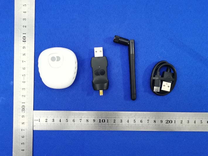
Click to zoom
Application Details
- Equipment Class
- DTS - Digital Transmission System
- Date of Grant
- Jul 12, 2021
- Application Purpose
- Original Equipment
- Date of Application
- Jul 12, 2021
- Equipment Note
- DecaMove
- Frequency Range
- 2402.00000000 - 2480.00000000
- Company
- Megadodo Games Co., Ltd.
- Country
- Thailand
Documents & Files
Document Text
Text extracted from the exhibit documents filed with the FCC. Open a document above to read the original.
Users Manual
DECA Move & Dongle Product details Power, charge and state indicator USB C port for Charging and debuging Clip Power and state indicator Antenna Button Setup 2. Connect DecaMove dongle to PC Screw-in the extended range antenna to the USB dongle and connect the dongle to your PC to any USB port. 1. Download and install deca hub Requirements: -Steam VR -Windows 10 Download and Install the DecaHub installer from this link: https://www.deca.net/decamove/setup Open the DecaHub software from your Windows Start menu DecaHub software will show the connection status change from ?Closed? to ?Open?. It is recommended to connect the DecaMove dongle to a front USB port if available. 3. Pairing Turn on the DecaMove by pressing the button for 2 seconds. DecaMove LED will change from orange (not connected) to blue when it successfully connects to dongle. Setup Notice the connection status changes to ?Streaming? and the compass icon rotates according to how you rotate your DecaMove. Pairing should happen automatically once the dongle is connected and theDecaMove is switched on. Please refer to the troubleshooting section for any issue. 4. Calibration (For first time use only) DecaMove delivers precise, low latency, and high accuracy hip tracking. The device? sensor fusion relies heavily on the magnetometer which MUST be calibrated before first use. Calibration is easy and should take less than 20 seconds, please forllow the instructions in this link: https://www.deca.net/decamove/support/decamove-magnetometer -calibration-procedure/ Setup 5. Fit The DecaMove can be placed anywhere along the waist and hip area but we recommend placing it on the sides so that it doesn?t interfere with crouching down or bending forward. 6. Launch games from decahub Launch Tab In order to support many games without the need for the game developer to install the devices? SDK, it?s important that you launch games from the DecaHub. Go to the Home tab and click the game you want to play (e.g. Pavlov VR) A check mark next to it means that DecaMove supports this game. 7. In game calibration Calibration is needed at the start of every gameplay session and at any time you feel the device heading has drifted. DecaMove?s gestured calibration does not require any special settings or any pressing of buttons: Simply hold your controllers close together in front of your hips. Make sure your hands point in the same direction as your head. Then look forward and don?t move for 1 second. You will see the ?Calibrating? ? message show up, hold the position until it?s complete. That?s it. You are calibrated. 8. Game settings Once the game is running, go to the game settings menu and make sure that the locomotion method is set on continuous and head-oriented and set the dominant hand to right-handed. Also, depending on the game, remove any joystick manipulation mechanism (e.g. locking the joystick in Contractors, or smoothing the joystick in Boneworks). This is a very important step. Without removing it, the movement will be wrong. Try pushing the left joystick forward to walk around, you will see that your movement is now relative to your hip. Enjoy the game with DecaMove! 9. DecaMove In-Game UI The DecaMove does one thing and it does it efficiently and accurately. It allows you to navigate with your hip with minimal drift so that your movement direction can be independent from your headset or hand controllers. It may take a bit of time to get used to this type of navigation control, especially if you are used to playing with controller-based movement, but it will give you an advantage against other non-DecaMovers. We add an In-Game UI that shows your hip headings and the DecaMove battery gauge. You can turn it On or Off by clicking on the DecaMove button. Visit the Tips section for more info of how to use the DecaMove properly. Setup Charging DecaMove To charge the DecaMove, please connect it to a USB port on your laptop or PC using the provided USB cable. Indicator states 1. DecaMove OFF: LED is off Dongle OFF: LED is off 2. DecaMove ON but not connected to dongle: LED is Orange Dongle connected to PC but not connected to DecaMove: - LED is steady red (com port open) - LED blinks red (com port closed) 3. DecaMove is turned on and connected to dongle: LED is blue Dongle connected to PC and DecaMove: - LED is steady blue (com port open) - LED blinks blue (com port closed) 4. DecaMove Battery Low/Charging: LED is steady red DecaMove Battery level extremely (<5%): LED blinks red 5. DecaMove Charging complete: LED is white Button operation 1. Long Press button for more than 1 second to: - Turn ON DecaMove if it is OFF or sleep mode - Set DecaMove to sleep if it is ON 6. DecaMove Sleep mode: DecaMove connected to dongle:- LED blinks blue DecaMove disconnected from dongle:- LED blinks orange 2. Long Press button for more than 2 seconds to enter Device Firmware Update mode, when usb cable is connected Indicator states 3. Short press button (<500ms) to send button press indication to host (PC): - Single press - sends single click indication to host - Double press - sends double click indication to host - Triple press - sends triple click indication to host 7. DecaMove device identification: When device identification command is sent to deca move, LED will blink with whichever color that is on Problems and troublshooting 1.DecaMove is not connecting • If the DecaMove dongle LED is solid red and the DecaMove LED is solid yellow it means that the dongle BLE port memo『ywasn ’ t clear for some sort of reason (can happen with multiple DecaMoves in the same environment). Fix: Unplug the dongle, wait 3 seconds and plug it again. •If the DecaMove dongle LED show solid blue and the DecaMove LED is solid blue it means that the device is paired and either: • It's not streaming quaternion data from some sort of reason: Fix - Unplug the dongle, wait 3 seconds and plug it again. • Or its SteamVR driver wasn ’ t loaded: Fix - Restart SteamVR 2.Game is not shown in the…
Text truncated - open the document above for the full version.
Cover Letter(s)
Date: Jul.09.2021 Equipment Autorisation Division Federal Communications Commission 7435 Oakland Mills Road Columbia, MD 21046 FCC ID: 2AZ4L-DM-001C Product Name: DecaMove Request for Confidentiality Pursuant to Sections 0.457 and 0.459 of the commission’s rules, we hereby request that the following documents be held confidential: (List here the documents for which you are seeking confidentiality – for example ...) • Schematics • Block diagram • Operation description These materials contain trade secrets and proprietary information and are not customarily released to the public. The public disclosure of this information might be harmful to the company and provide unjustified benefits to our competitors. <Signature> Name: Or Kuntzman Title: Managing Director Company: [email protected]
Cover Letter(s)
Date: Jul.09.2021 Federal Communications Commission Authorization & Evaluation Division 7345 Oakland Mills Road Columbia, Maryland 21046 RE: LETTER OF AGENT AUTHORIZATION To Whom It May Concern: We, the undersigned, hereby authorize Compliance Testing, LLC to act on our behalf in all matters relating to application for equipment authorization, including the signing of all documents relating to these matters. We also hereby certify that no party to the application authorized hereunder is subject to the denial of benefits, including FCC benefits, pursuant to Section 5301 of the Anti-Drug Abuse Act of 1988, 21 U.S.C.853(a). Sincerely, <Signature> Name: Or Kuntzman Title: Managing Director Company: Megadodo Games Co., Ltd.
Cover Letter(s)
Date: Jul.09.2021 Federal Communications Commission Authorization & Evaluation Division 7345 Oakland Mills Road Columbia, Maryland 21046 Authority to Act as Agent On our behalf, I appoint Shenzhen CTB Testing Technology Co., Ltd. Add: Floor 1&2, Building A, No. 26 of Xinhe Road, Xinqiao Community, Xinqiao Street, Baoan District, Shenzhen, Guangdong, China to act as our agent in the preparation of this application for equipment certification. I certify that submitted documents properly describe the device or system for which equipment certification is sought. I also certify that each unit manufactured, imported or marketed, as defined in the Federal Communications Commission’s regulations will have affixed to it a label identical to that submitted for approval with this application. For instances where our authorized agent signs the application for certification on our behalf, I acknowledge that all responsibility for complying with the terms and conditions for certification, still resides with Megadodo Games Co., Ltd. Add: No.24 Sukhumvit Soi 43, Klongton Nua, Wattana, Bangkok , THAILAND 10110 <Signature> Name: Or Kuntzman Title: Managing Director Company: Megadodo Games Co., Ltd.
External Photos
External Photos TX RX
ID Label/Location Info
Model: DM-001C FCC ID: 2AZ4L-DM-001C Label Location
Internal Photos
Internal Photos ANT
RF Exposure Info
Shenzhen CTB Testing Co., Ltd. 2AZ4L-DM-001C Portable device According to §15.247(e)(i) and §1.1307(b)(1), systems operating under the provisions of this section shall be operated in a manner that ensures that the public is not exposed to radio frequency energy level in excess of the Commission’s guidelines. According to KDB447498 D01 General RF Exposure Guidance V06 The 1-g SAR and 10-g SAR test exclusion thresholds for 100 MHz to 6 GHz at test separation distances ≤ 50 mm are determined by: [(max. power of channel, including tune-up tolerance, mW)/(min. test separation distance, mm)]·[√f(GHZ)] ≤ 3.0 for 1-g SAR and ≤ 7.5 for 10-g extremity SAR, where: • f(GHZ) is the RF channel transmit frequency in GHz • Power and distance are rounded to the nearest mW and mm before calculation • The result is rounded to one decimal place for comparison When the minimum test separation distance is < 5 mm, a distance of 5 mm is applied to determine SAR test exclusion. BT: Modulation Channel Freq. (GHz) Conduct ed power (dBm) Conducte d power (mW) Tune-up power (dBm) Max tune-up power (dBm) Max tune-up power (mW) Distance (mm) Result calculatio n SAR Exclusion threshold SAR test exclusion 2.402-3.0260.50-3±1-2.000.63<50.195583.00YES 2.441-2.5710.55-2±1-1.000.79<50.248213.00YES 2.480-2.8390.52-2±1-1.000.79<50.250183.00YES GFSK Conclusion: For the max result : 0. 25018≤ FCC Limit 3.0 for 1g SAR.
Test Report
Shenzhen CTB Testing Technology Co., Ltd. Report No.: CTB210622007RFX Report Tel: 4008-707-283Web: http://www.ctb-lab.netPage 1 of 36 TEST REPORT Compiled by: Reviewed by: Approved by: Arron Liu Bin Mei Rita Xiao / Director The test report is effective only with both signature and specialized stamp. This result(s) shown in this report refer only to the sample(s) tested. Without written approval of Shenzhen CTB Testing Technology Co., Ltd. this report can’t be reproduced except in full. The tested sample(s) and the sample information are provided by the client. Product Name: DecaMove FCC ID: 2AZ4L-DM-001C Trademark: N/A Model Number: DM-001C Prepared For: Megadodo Games Co., Ltd. Address: No.24 Sukhumvit Soi 43, Klongton Nua, Wattana, Bangkok , THAILAND 10110 Manufacturer: Megadodo Games Co., Ltd. Address: No.24 Sukhumvit Soi 43, Klongton Nua, Wattana, Bangkok , THAILAND 10110 Prepared By: Shenzhen CTB Testing Technology Co., Ltd. Address: Floor 1&2, Building A, No. 26 of Xinhe Road, Xinqiao Community, Xinqiao Street, Baoan District, Shenzhen, Guangdong China Sample Received Date: Jun. 16, 2021 Sample tested Date: Jun. 16, 2021 to Jun. 23, 2021 Issue Date: Jul. 7, 2021 Report No.: CTB210622007RFX Te s t Standards FCC Part15.247 ANSI C63.10:2013 Test Results PASS Remark: This is Bluetooth radio test report. Shenzhen CTB Testing Technology Co., Ltd. Report No.: CTB210622007RFX Report Tel: 4008-707-283 Web: http://www.ctb-lab.net Page 2 of 36 TABLE OF CONTENT Test Report Declaration Page 1. VERSION............................................................ 4 2. TEST SUMMARY ..................................................... 5 3. MEASUREMENT UNCERTAINTY ....................................... 6 4. PRODUCT INFORMATION AND TEST SETUP ........................... 7 4.1 Product Information ..................................................... 7 4.2 Test Setup Configuration ................................................ 7 4.3 Support Equipment ..................................................... 7 4.4 Channel List ........................................................... 8 4.5 Test Mode ............................................................. 8 4.6 Test Environment ....................................................... 8 5. TEST FACILITY AND TEST INSTRUMENT USED ......................... 9 5.1 Test Facility ............................................................ 9 5.2 Test Instrument Used ................................................... 9 6. AC POWER LINE CONDUCTED EMISSION .............................. 11 6.1 Block Diagram Of Test Setup............................................ 11 6.2 Limit ................................................................. 11 6.3 Test procedure ........................................................ 11 6.4 Test Result ........................................................... 13 7. RADIATED SPURIOUS EMISSION ..................................... 15 7.1 Block Diagram Of Test Setup............................................ 15 7.2 Limit ................................................................. 15 7.3 Test procedure ........................................................ 16 7.4 Test Result ........................................................... 17 8. BAND EDGE AND RF COUNDUCTED SPURIOUS EMISSIONS ............ 24 8.1 Block Diagram Of Test Setup............................................ 24 8.2 Limit ................................................................. 24 8.3 Test procedure ........................................................ 24 8.4 Test Result ........................................................... 25 9. COUDUCTED PEAK OUTPUT POWER ................................. 27 9.1 Block Diagram Of Test Setup............................................ 27 9.2 Limit ................................................................. 27 9.3 Test procedure ........................................................ 27 9.4 Test Result ........................................................... 28 10. 6DB OCCUPIED BANDWIDTH ........................................ 30 10.1 Block Diagram Of Test Setup .......................................... 30 10.2 Limit ................................................................ 30 10.3 Test procedure ....................................................... 30 10.4 Test Result .......................................................... 30 11. POWER SPECTRAL DENSITY ........................................ 32 11.1 Block Diagram Of Test Setup .......................................... 32 11.2 Limit ................................................................ 32 Shenzhen CTB Testing Technology Co., Ltd. Report No.: CTB210622007RFX Report Tel: 4008-707-283 Web: http://www.ctb-lab.net Page 3 of 36 11.3 Test procedure ....................................................... 32 11.4 Test Result .......................................................... 32 12. ANTENNA REQUIREMENT ........................................... 34 13. EUT TEST SETUP PHOTOGRAPHS ................................... 35 (Note: N/A means not applicable) Shenzhen CTB Testing Technology Co., Ltd. Report No.: CTB210622007RFX Report Tel: 4008-707-283 Web: http://www.ctb-lab.net Page 4 of 36 1. VERSION Report N o. Issue Date Description Approved CTB210622007RFX Jul. 7, 2021 Original Valid Shenzhen CTB Testing Technology Co., Ltd. Report No.: CTB210622007RFX Report Tel: 4008-707-283 Web: http://www.ctb-lab.net Page 5 of 36 2. TEST SUMMARY The Product has been tested according to the following specifications: Test Item Test Requirement Test method Result AC Power Line Conducted Emission 47 CFR Part 15 Subpart C Section 15.207 ANSI C63.10-2013 PAS S Radiated Spurious emissions 47 CFR Part 15 Subpart C Section 15.205/15.209 ANSI C63.10-2013 PAS S Band edge and RF Conducted Spurious Emissions 47 CFR Part 15 Subpart C Section 15.247(d)/15.205(a) ANSI C63.10-2013 PAS S Conducted Peak Output Power 47 CFR Part 15 Subpart C Section 1…
Text truncated - open the document above for the full version.
Test Setup Photos
Radiated Emission Below 1G Above 1G Conducted Emission
Contact Information
Applicant
Or Kuntzman(Managing Director)
Test Firm
Shenzhen CTB Testing Technology Co., Ltd.Rita Xiao
[email protected]86-13538218145
Technical Specifications
| # | Rule Parts | Frequency Range | Power Output |
|---|---|---|---|
| 1 | 15C | 2.40 GHz - 2.48 GHz | 553.00 µW |