2AZ6A-GSIGCMGround Conductivity Meter
Geosensors Inc.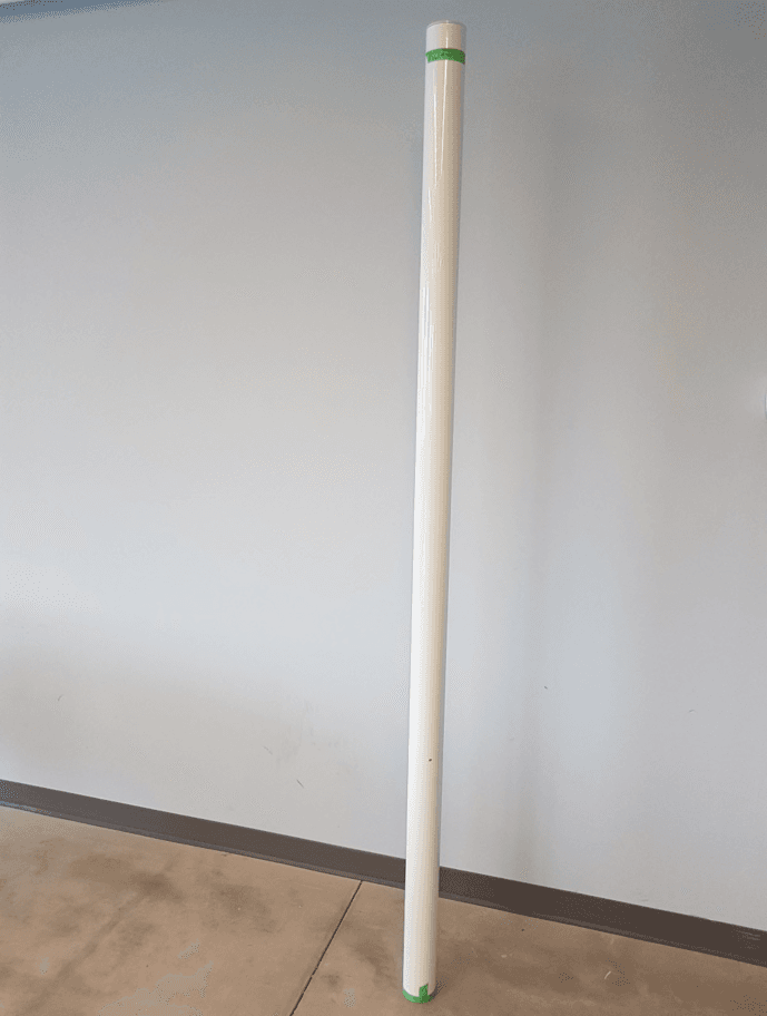
Click to zoom
Application Details
- Equipment Class
- DCD - Part 15 Low Power Transmitter Below 1705 kHz
- Date of Grant
- Jul 11, 2021
- Application Purpose
- Original Equipment
- Date of Application
- Jul 08, 2021
- Equipment Note
- Ground Conductivity Meter
- Frequency Range
- 0.00840000 - 0.00960000
- Company
- Geosensors Inc.
- Country
- Canada
Documents & Files
Document Text
Text extracted from the exhibit documents filed with the FCC. Open a document above to read the original.
Users Manual
GEOSENSORS R6™ OPERATOR’S MANUAL Geosensors Inc. 66 Mann Ave. Toronto V2.1 updated 30 June, 2021 DRAFT ii R6 Operators Reference Manual.docx (THIS PAGE INTENTIONALLY LEFT BLANK) DRAFT iii R6 Operators Reference Manual.docx Table of Contents FCC Regulatory Statements ..................................................................................................................... v ISED Regulatory Statements................................................................................................................... vi EU Regulatory Statements .................................................................................................................... vii Technical Specification ......................................................................................................................... viii Important Information and Sample Label .............................................................................................. ix 1 Overview ....................................................................................................................................... 1 1.1 Intended Use: ............................................................................................................................... 1 1.2 Description: .................................................................................................................................. 1 1.3 Basis of Operation: ....................................................................................................................... 2 2 What’s in the Package? .................................................................................................................. 4 2.1 Installing the R6™ Unit: ................................................................................................................ 4 3 Cabling and Power Supplies ........................................................................................................... 4 3.1 Data and Motorized Surveying Cables: ........................................................................................ 4 4 Operating the R6™ ......................................................................................................................... 5 4.1 Pre-survey considerations, precautions and checklist .................................................................. 5 4.2 Power-on ...................................................................................................................................... 6 4.3 Survey methodology .................................................................................................................... 6 4.4 Power-off ................................................................................................................................... 10 4.5 Configuring Sensor Output ......................................................................................................... 10 5 Streaming Data ............................................................................................................................ 10 5.1 Connecting a computer or data logger to the R6™ .................................................................... 11 5.2 Inspection and Maintenance ...................................................................................................... 11 6 Troubleshooting Guide ................................................................................................................ 12 6.1 Electrical, Cables and Connection Issues .................................................................................... 12 6.2 EM Interference ......................................................................................................................... 14 6.3 NMEA-Mode Operation ............................................................................................................. 15 6.4 Changing Sensor Operating Parameters .................................................................................... 15 Appendix A: Output Data Formats ....................................................................................................... 16 Appendix B: Geosensors R6™ Technical Specifications ......................................................................... 18 DRAFT iv R6 Operators Reference Manual.docx Appendix C: Manufacturer’s Contact Information ................................................................................ 20 (THIS PAGE INTENTIONALLY LEFT BLANK) DRAFT v R6 Operators Reference Manual.docx FCC Regulatory Statements This device complies with Part 15 of the FCC Rules. Operation is subject to the following two conditions: (1) This device may not cause harmful interference. (2) This device must accept any interference received, including interference that may cause undesired operation. This equipment has been tested and found to comply with the limits for a Class B digital device, pursuant to part 15 of the Federal Communication Commission (FCC) rules. These limits are designed to provide reasonable protection against harmful interference in a residential installation. This equipment generates, uses and can radiate radio frequency energy and, if not installed and used in accordance with the instructions, may cause harmful interference to radio communications. However, there is no guarantee that interference will not occur in a particular installation. If this equipment causes harmful interference to radio or television reception, which can be determined by turning the equipment off and on, the user is encouraged to try to correct the interference by doing one or more of the following measures: • Reorient or relocate the receiving antenna. • Increase the separation between the equipment and receiver. • Connect the equipment into an outlet on a circuit different from that to which the receiver is connected. • Consult the dealer or an experienced radio/TV technician for help. NOTE: THE GRAN…
Text truncated - open the document above for the full version.
Cover Letter(s)
66 Mann Ave. Toronto, Ontario M4S 2Y3 Tel: (416) 483-4691 Cell: (416) 892-0382 Date 10/05/2021 TUV SUD America Inc. 10 Centennial Drive Peabody, MA 01960, USA Dear Sir or Madam, We, Geosensors Inc, hereby authorize Amir Emami of TUV SUD Canada Inc., 11 Gordon Collins Drive, Gormley, L0H 1G0, Canada; 905-883-7255 to act as our agent in all matters relating to applications for equipment authorization, including the signing of all documents relating to these matters. Yours sincerely, Name: John Scott Holladay III Title: President
Cover Letter(s)
66 Mann Ave. Toronto, Ontario M4S 2Y3 Tel: (416) 483-4691 Cell: (416) 892-0382 Date 22/06/2021 Federal Communications Commission Equipment Authorization Branch 7435 Oakland Mills Road Columbia, MD 21046 Confidentiality Request FCC ID: 2AZ6A-GSIGCM Pursuant to Sections 0.457(d)(1)(ii) and 0.459 of the Commission’s Rules, Geosensors Inc. hereby requests permanent confidential treatment of information accompanying this application as outlined below: Schematics Bill of Materials/Parts List Block Diagrams Theory of Operation Geosensors Inc also hereby requests short-term confidential treatment of information accompanying this application as outlined below for a period of period of 180 days: Internal Photos External Photos User Manual Test Set-up Photographs The above materials contain trade secrets and proprietary information not customarily released to the public. The public disclosure of these matters might be harmful to the Applicant and provide unjustified benefits to its competitors. The Applicant understands that pursuant to Rule 0.457(d)(1)(ii), disclosure of this Application and all accompanying materials will not be made before the date of the Grant for this Application. Yours sincerely, Name: John Scott Holladay III Company: Geosensors Inc
External Photos
Report File #: 7169009616RF-000 © TÜV SÜD Canada Inc. This test report shall not be reproduced except in full, without written approval of TÜV SÜD Canada Inc. Exhibit: External Photos FCC ID: 2AZ6A-GSIGCM IC: 27333-GSIGCM Client Geosensors, Inc. Product R-Series Ground Conductivity Meter Standard(s) RSS 210 Issue 10:2019 FCC Part 15 Subpart 15.209 Page 2 of 3 Report Issued: 6/28/2021 Report File #: 7169009616RF-000 © TÜV SÜD Canada Inc. This test report shall not be reproduced except in full, without written approval of TÜV SÜD Canada Inc. Figure 1 – EUT External Photo Client Geosensors, Inc. Product R-Series Ground Conductivity Meter Standard(s) RSS 210 Issue 10:2019 FCC Part 15 Subpart 15.209 Page 3 of 3 Report Issued: 6/28/2021 Report File #: 7169009616RF-000 © TÜV SÜD Canada Inc. This test report shall not be reproduced except in full, without written approval of TÜV SÜD Canada Inc. Figure 2 – EUT External Photo (Connector)
ID Label/Location Info
Report File #: 7169009616RF-000 © TÜV SÜD Canada Inc. This test report shall not be reproduced except in full, without written approval of TÜV SÜD Canada Inc. Exhibit: Sample Label & Location FCC ID: 2AZ6A-GSIGCM IC: 27333-GSIGCM Client Geosensors, Inc. Product R-Series Ground Conductivity Meter Standard(s) RSS 210 Issue 10:2019 FCC Part 15 Subpart 15.209 Page 2 of 4 Report Issued: 6/28/2021 Report File #: 7169009616RF-000 © TÜV SÜD Canada Inc. This test report shall not be reproduced except in full, without written approval of TÜV SÜD Canada Inc. Label Location Client Geosensors, Inc. Product R-Series Ground Conductivity Meter Standard(s) RSS 210 Issue 10:2019 FCC Part 15 Subpart 15.209 Page 3 of 4 Report Issued: 6/28/2021 Report File #: 7169009616RF-000 © TÜV SÜD Canada Inc. This test report shall not be reproduced except in full, without written approval of TÜV SÜD Canada Inc. Sample Labels Client Geosensors, Inc. Product R-Series Ground Conductivity Meter Standard(s) RSS 210 Issue 10:2019 FCC Part 15 Subpart 15.209 Page 4 of 4 Report Issued: 6/28/2021 Report File #: 7169009616RF-000 © TÜV SÜD Canada Inc. This test report shall not be reproduced except in full, without written approval of TÜV SÜD Canada Inc.
Internal Photos
Report File #: 7169009616RF-000 © TÜV SÜD Canada Inc. This test report shall not be reproduced except in full, without written approval of TÜV SÜD Canada Inc. Exhibit: Internal Photos FCC ID: 2AZ6A-GSIGCM IC: 27333-GSIGCM Client Geosensors, Inc. Product R-Series Ground Conductivity Meter Standard(s) RSS 210 Issue 10:2019 FCC Part 15 Subpart 15.209 Page 2 of 3 Report Issued: 6/28/2021 Report File #: 7169009616RF-000 © TÜV SÜD Canada Inc. This test report shall not be reproduced except in full, without written approval of TÜV SÜD Canada Inc. Figure 1 – EUT Internal Photo Front Figure 2 – EUT Internal Photo Back Figure 3 – EUT Internal Photo Antenna Figure 4 – EUT Internal Photo Antenna GPS Module Wi-FiModule Client Geosensors, Inc. Product R-Series Ground Conductivity Meter Standard(s) RSS 210 Issue 10:2019 FCC Part 15 Subpart 15.209 Page 3 of 3 Report Issued: 6/28/2021 Report File #: 7169009616RF-000 © TÜV SÜD Canada Inc. This test report shall not be reproduced except in full, without written approval of TÜV SÜD Canada Inc. Figure 5 – EUT Internal Photo Antenna Figure 6 – EUT Internal Photo Antenna Figure 7 – EUT Internal Photo Antenna Figure 8 – EUT Internal Photo Antenna
RF Exposure Info
Report File #: 7169009616RF-000 © TÜV SÜD Canada Inc. This test report shall not be reproduced except in full, without written approval of TÜV SÜD Canada Inc. Exhibit: RF Exposure – FCC FCC ID: 2AZ6A-GSIGCM Client Geosensors, Inc. Product R-Series Ground Conductivity Meter Standard(s) FCC KDB 447498:2015 Page 2 of 5 Report Issued: 7/6/2021 Report File #: 7169009616RF-000 © TÜV SÜD Canada Inc. This test report shall not be reproduced except in full, without written approval of TÜV SÜD Canada Inc. RF Exposure – FCC The device is a mobile device intended to generally be used in such a way that a separation distance of at least 20 centimeters is normally maintained between the transmitter's radiating structure and the body of the user or nearby persons. The EUT contains a 9kHz transmitter and a modularly certified 2400 – 2483.5 MHz DTS transmitter. For the 9kHz transmitter, an inquiry was submitted to FCC and the limits for both E-field and H-field in KDB publication 680106 may be used to show compliance for the EUT. Radiofrequency Radiation Exposure Evaluation: Mobile Devices Mobile devices shall be evaluated for RF radiation exposure according to the provisions of FCC §2.1091 and the MPE guidelines identified in FCC §1.1310. As per FCC §1.1310 Table 1(B), the limit for Maximum Permissible Exposure (MPE) to radiofrequency electromagnetic fields for General Population/Uncontrolled Exposure in the frequency range of 300 MHz to 1.5 GHz is f/1500 mW/cm 2 and in the frequency range of 1.5GHz to 100GHz is 1.0 mW/cm 2 . Where f = frequency in MHz. The power density formula is given by: P d = (P out *G) / (4*pi*R 2 ) Where, P d = Power density in mW/cm 2 P out = Conducted output power to antenna in mW G = Numeric Antenna Gain Pi = 3.1416 R = Separation distance in cm Max power densities (Pd), for the Wi-Fi Module is shown below, as per the FCC approval grant. Transceiver FCC ID Max Power Density (Pd) mW/cm2 2.4GHz Wi-Fi 2AC7Z-ESP32WROOM32U 0.0132 Client Geosensors, Inc. Product R-Series Ground Conductivity Meter Standard(s) FCC KDB 447498:2015 Page 3 of 5 Report Issued: 7/6/2021 Report File #: 7169009616RF-000 © TÜV SÜD Canada Inc. This test report shall not be reproduced except in full, without written approval of TÜV SÜD Canada Inc. Supplementary Procedure for Assessing Compliance with Nerve Stimulation Exposure Limits Purpose Evaluation of RF Exposure test data for determining compliance of systems operating at frequencies below 100 kHz is provided on a case-by-case basis following an FCC KDB inquiry. An inquiry was submitted and the limits for both E-field and H-field in KDB publication 680106 may be used to show compliance for the EUT (R-Series Ground Conductivity Meter) Limit(s) and Method The limits applied are as per KDB 680106 Section 3 and as defined in SPR-002 Table 2. Whole Body/Torso/Head limits for general public exposure were applied as worst case. The method used is the Direct Measurement as detailed in SPR-002 section: 6.6.1.1 and KDB 680106 Section 3.a)(2). The minimum distance an operator will be from the EUT during normal operation would be more than 20cm. The measurements were maximized and done with the field probe 20cm away from the transmitter. Results The EUT passed the requirements. The EUT was checked along the roll angle to find the worst-case emission. The E- and H-field were measured with a field probe 20cm away from the transmitter at position 1 and 2 as shown in the diagram below and worst-case results were obtained at position 2. The results are indicated in the table below. Measured Field Limit Results Electric Field (V/m) 10.40 V/m peak 83.0 V/m r.m.s Pass Magnetic Field (A/m) 28.59 A/m peak 90.0 A/m r.m.s Pass Field Probe Position Diagram EUT 1 2 Tx 20cm Client Geosensors, Inc. Product R-Series Ground Conductivity Meter Standard(s) FCC KDB 447498:2015 Page 4 of 5 Report Issued: 7/6/2021 Report File #: 7169009616RF-000 © TÜV SÜD Canada Inc. This test report shall not be reproduced except in full, without written approval of TÜV SÜD Canada Inc. Graphs H-Field E-Field Client Geosensors, Inc. Product R-Series Ground Conductivity Meter Standard(s) FCC KDB 447498:2015 Page 5 of 5 Report Issued: 7/6/2021 Report File #: 7169009616RF-000 © TÜV SÜD Canada Inc. This test report shall not be reproduced except in full, without written approval of TÜV SÜD Canada Inc. Test Equipment List Equipment Model No. Manufacturer Last Calibration Date Next Calibration Date Asset SN Electric and Magnetic Field Analyzer EHP-200AC Narda Dec 17, 2019Dec 17, 2021 170WX 90213 Emission Software EHP200-TS Narda NCR NCR N/A
Test Report
Registration # 6844A-3 Testing Laboratory Certificate #2955.02 R-14023, G-20072 C-14498, T-20060 Registration # CA6844 Page 1 of 26 Report Issued: 7/5/2021 Report File #: 7169009616RF-000 © TÜV SÜD Canada Inc. This test report shall not be reproduced except in full, without written approval of TÜV SÜD Canada Inc. RF Test Report As per RSS-210 Issue 10:2019 & FCC Part 15 Subpart 15.209 Low Power Licence Exempt Radio Communication Devices Intentional Radiators on the R-Series Ground Conductivity Meter Issued by: TÜV SÜD Canada Inc. 11 Gordon Collins Dr, Gormley, ON, L0H 1G0 Canada Ph: (905) 883-7255 Testing produced for See Appendix A for full client & EUT details. Prepared by: Amir Emami, Project Engineer Reviewed by: Min Xie, Sr. Project Engineer Client Geosensors, Inc. Product R-Series Ground Conductivity Meter Standard(s) RSS 210 Issue 10:2019 FCC Part 15 Subpart 15.209 Page 2 of 26 Report Issued: 7/5/2021 Report File #: 7169009616RF-000 © TÜV SÜD Canada Inc. This test report shall not be reproduced except in full, without written approval of TÜV SÜD Canada Inc. Table of Contents Table of Contents ................................................................................................................... 2 Report Scope .......................................................................................................................... 3 Summary ................................................................................................................................ 4 Test Results Summary ....................................................................................................... 5 Notes, Justifications, or Deviations ................................................................................... 6 Sample Calculation(s) ........................................................................................................ 6 Applicable Standards, Specifications and Methods ............................................................... 7 Document Revision Status ..................................................................................................... 8 Definitions and Acronyms ..................................................................................................... 9 Testing Facility .................................................................................................................... 10 Calibrations and Accreditations ....................................................................................... 10 Testing Environmental Conditions and Dates ................................................................. 11 Detailed Test Results Section .............................................................................................. 12 Transmitter Spurious Radiated Emissions ....................................................................... 13 Emission Bandwidth ........................................................................................................ 21 Appendix A – EUT Summary .............................................................................................. 24 Appendix B – EUT and Test Setup Photos .......................................................................... 26 Client Geosensors, Inc. Product R-Series Ground Conductivity Meter Standard(s) RSS 210 Issue 10:2019 FCC Part 15 Subpart 15.209 Page 3 of 26 Report Issued: 7/5/2021 Report File #: 7169009616RF-000 © TÜV SÜD Canada Inc. This test report shall not be reproduced except in full, without written approval of TÜV SÜD Canada Inc. Report Scope This report addresses the EMC verification testing and test results of the Ground Conductivity Meter Model: R-Series, herein referred to as EUT (Equipment Under Test). The EUT was tested for compliance against the following standards: RSS-210 Issue 10:2019 FCC Part 15 Subpart C 15.209 Test procedures, results, justifications, and engineering considerations, if any, follow later in this report. This report does not imply product endorsement by any government, accreditation agency, or TÜV SÜD Canada Inc. Opinions or interpretations expressed in this report, if any, are outside the scope of TÜV SÜD Canada Inc. accreditations. Any opinions expressed do not necessarily reflect the opinions of TÜV SÜD Canada Inc., unless otherwise stated. Client Geosensors, Inc. Product R-Series Ground Conductivity Meter Standard(s) RSS 210 Issue 10:2019 FCC Part 15 Subpart 15.209 Page 4 of 26 Report Issued: 7/5/2021 Report File #: 7169009616RF-000 © TÜV SÜD Canada Inc. This test report shall not be reproduced except in full, without written approval of TÜV SÜD Canada Inc. Summary The results contained in this report relate only to the item(s) tested. EUT: Ground Conductivity Meter, Model: R6 FCC Certification #, FCC ID: 2AZ6A-GSIGCM ISED Certification #, IC: 27333-GSIGCM EUT passed all tests performed Yes Tests conducted by Amir Emami Report reviewed by Min Xie For testing dates, see "Testing Environmental Conditions and Dates". The EUT is considered to have been received the date of the commencement of the first test, unless otherwise stated. For a close-up picture of the EUT, see ‘Appendix B – EUT and Test Setup Photos’. Client Geosensors, Inc. Product R-Series Ground Conductivity Meter Standard(s) RSS 210 Issue 10:2019 FCC Part 15 Subpart 15.209 Page 5 of 26 Report Issued: 7/5/2021 Report File #: 7169009616RF-000 © TÜV SÜD Canada Inc. This test report shall not be reproduced except in full, without written approval of TÜV SÜD Canada Inc. Test Results Summary Standard/Method Description Class/Limit Result FCC 15.203 Antenna Requirement Unique Pass See Justification RSS-GEN Section 6.7 Occupied Bandwidth 99% OBW Pass FCC 15.205 RSS-GEN (Table 7) Restricted Bands for Intentional Operation QuasiPeak Average Pass FCC 15.207 RSS-GEN (Table 4) Power Line Conducted Emissions QuasiPeak Average N/A See Justification FCC 15.209 RSS-GEN – Clause 8.9 Transmitter Spurious Radiated Emissions QuasiPeak Averag…
Text truncated - open the document above for the full version.
Test Setup Photos
Report File #: 7169009616RF-000 © TÜV SÜD Canada Inc. This test report shall not be reproduced except in full, without written approval of TÜV SÜD Canada Inc. Exhibit: Test Setup Photos FCC ID: 2AZ6A-GSIGCM IC: 27333-GSIGCM Client Geosensors, Inc. Product R-Series Ground Conductivity Meter Standard(s) RSS 210 Issue 10:2019 FCC Part 15 Subpart 15.209 Page 2 of 3 Report Issued: 6/28/2021 Report File #: 7169009616RF-000 © TÜV SÜD Canada Inc. This test report shall not be reproduced except in full, without written approval of TÜV SÜD Canada Inc. Figure 1 ‒ Radiated Emissions Setup – Photo 1 9kHz – 30MHz Client Geosensors, Inc. Product R-Series Ground Conductivity Meter Standard(s) RSS 210 Issue 10:2019 FCC Part 15 Subpart 15.209 Page 3 of 3 Report Issued: 6/28/2021 Report File #: 7169009616RF-000 © TÜV SÜD Canada Inc. This test report shall not be reproduced except in full, without written approval of TÜV SÜD Canada Inc. Figure 2 ‒ Radiated Emissions Setup – Photo 2 30MHz – 1GHz
Contact Information
Applicant
John Scott Holladay(President)
Test Firm
TUV SUD CANADA (Gormley)William (Mac) Elliott
[email protected]813-284-2736
Technical Specifications
| # | Rule Parts | Frequency Range | Power Output |
|---|---|---|---|
| 1 | 15C | 0.0084 MHz - 0.0096 MHz | - |